Page is loading ...

Scope Communications UK Ltd
Quantum House, Totnes, Devon TQ9 5AL England.
Tel: 01803 860700 Email: sales@scope-uk.com
Ref: RX4USER Issue 1
PRX4 & PRX4SERL
Four Zone Receiver Decoder
User Manual

PRX4 & PRX4SERL Four Zone Receiver Decoder
Ref: RX4USER Page 2 of 8 Issue 1
PREFACE
Important Installation Information
It is the purchasers’ responsibility to determine the suitability of this equipment and its
derivatives for any given application, Scope cannot give specific advice in this manual,
as each use will require independent evaluation.
Scope has, wherever possible, employed extra safeguards to monitor the system’s
performance. Certain system installations, operational requirements or budgets may,
however, limit the effectiveness of these safeguards. Again, the suitability of the system
for any given application must therefore be decided by the installer and their customer,
relative to the application and risk.
Good working practice dictates that a suitable system installation log must be
generated, together with a record of the dates when the system has been manually
checked, (with the aid of signal strength meters etc.) enabling the system performance
to be compared with the original installation data.
For UK equipment, Scope has no control of the use and application of the frequencies
issued by OFCOM. Some equipment that is licensed may have greater protection than
other equipment which is operated on a WT Act License Exempt basis.
The supply of this equipment is governed by our standard terms and conditions of sale,
which can be found on the reverse of all order acknowledgements*, proforma invoices*,
delivery notes, price lists and invoices. Alternatively, these can be provided on request.
* Faxed proforma invoices and quotations refer to “conditions available upon request”.
Important Safety Information
Scope products are designed to operate safely when installed and used according to
general safety practices. The following requirements should be observed at all times.
Do NOT subject this equipment to:
Mechanical shock, excessive humidity or moisture, extremes of temperature or
corrosive liquids.
This equipment is designed for indoor use, unless expressly stated otherwise, and must
not be used in classified Hazardous Areas, including areas containing explosive or
flammable vapours, unless express authorisation has been given in writing by the
manufacturer. If in doubt, consult your local product dealer for further information.
Do not obstruct any slots or openings in the product. These are provided for ventilation
to ensure reliable operation of the product and to protect it from overheating. Only use a
damp cloth for cleaning (not liquid or aerosol based cleaners), and ensure that any
power is removed from the unit prior to beginning the cleaning operation.
Removal of covers from the equipment must only be undertaken by authorised service
personnel, who must ensure that power is isolated prior to removal.

PRX4 & PRX4SERL Four Zone Receiver Decoder
Ref: RX4USER Page 3 of 8 Issue 1
Installation
Installation must only be undertaken by an Approved contractor, who shall ensure that
all work is carried out in compliance with National Wiring Regulations. For mains
powered equipment, a readily accessible isolating fuse or switched socket must be
located within 1 metre of the equipment.
No User Serviceable Parts
Alteration or modification to any part of this equipment, without the prior written consent
of the manufacturer, will invalidate all Approvals and Warranties attaching to the
equipment. Further liability for the operation of the equipment, under the applicable law,
will pass to the user, who will absolve the manufacturer of any further responsibility for
it’s correct operation and use.
Liability
Scope does not accept liability for any damage or injury, howsoever caused as the
result of misuse of this equipment. It is the responsibility of the user to ensure that the
equipment is operated in the manner for which it was intended and that it is the correct
item of equipment for the required task.
Warranty
This product is warranted as free from defects of workmanship and materials for a
period of one year from the original purchase date. During this time, if there is a defect
or malfunction of this product, Scope will, with proof of purchase, repair or replace at it’s
discretion any defective parts, free of charge. This does not include where the
adjustments, parts and repair are necessary due to circumstances beyond the control of
Scope, including but not limited to fire or other casualty, accident, neglect, abuse,
abnormal use or battery leakage damage.
WARNING ! No User Serviceable Parts
Celui-ci ne contient aucune piece pouvant etre reparee par l’utilisateur
Alteration or modification to any part of this equipment, without the prior written consent
of the manufacturer, will invalidate all manufacturer approvals and warranties. No
adjustments can be undertaken except by qualified and licensed persons as authorised
by Scope.
This product complies with the essential requirements of the R&TTE Directive 1999/5/EC.
Copies of the Declaration of Conformity covering this product can be obtained from Scope at:
Quantum House, Steamer Quay, Totnes TQ9 5AL United Kingdom.
Do not discard. At end of life this equipment must be sent to an authorised waste treatment centre.
Contact Scope at the above address for further details.
© Scope Communications UK Ltd, 2005 All Rights Reserved

PRX4 & PRX4SERL Four Zone Receiver Decoder
Ref: RX4USER Page 4 of 8 Issue 1
Overview
The PRX4 is a POCSAG receiver decoder equipped with four “change of state” relays.
It is designed to operate with the Scope Pagetek and Digilink transmitters.
Closing a zone input on the transmitter will cause the corresponding zone relay on the
PRX4 to energise and light the front panel LED for that relay. Opening a zone input on
the transmitter will cause the corresponding PRX4 zone relay and LED to de-energise.
All relays have N/O, N/C and Common connections available on screw terminal blocks
located on the main circuit board (see Diagram 1). The maximum contact rating of each
relay is 0.5A @ 125V ac, 1A @ 60V dc.
If necessary, the unit can be reset by depressing SW1 through the hole provided on the
lower endplate (see Diagram 1). This will de-energise all relays and return the system to
its initial power up state.
PRX4SERL: up to four capcode ranges (either alphanumeric or numeric) can be used
to latch four corresponding relays and their respective front panel LEDs. The relays can
be globally reset either using a preset over the air capcode or by depressing the Reset
switch. Optional software is available which only latches the relays for 3 seconds (for
1200 baud TX systems only). Ask our technical sales team for further details.
The PRX4SERL has the added facility of an RS232 serial port, providing a data logging
function (text only). The unit can optionally be configured to send Scope protocol for
onward transmission (using a Scope transmitter on a different frequency).
Power input for both units is 12V dc @ 0.5A, via the blue latching connector provided.
Section 1: Installation
Certain precautions in siting of the unit apply. As with all radio equipment, attention
must be given to the aerial selected and where the unit is mounted in relation to the
transmitter being monitored. If the unit is to be used with a second transmitter, it should
be sited as centrally as possible within the secondary area to be covered, although it
must of course, be within adequate distance of the originating transmitter. The unit
should be at least two metres away from any transmitter.
It is therefore essential that adequate signal reception is checked before fitting the unit
in the desired location. Using a Yaesu VR-120D Communications Receiver*
programmed to the required frequency, a signal strength of 5 or greater is deemed to be
sufficient to provide a reliable consistent link. Readings below this level may lead to
poor reception in adverse atmospheric conditions.
Ranges of up to 1 mile can be achieved, except where signal paths are severely
obstructed due to reflections or physical obstacles in the way. Such conditions may be
experienced where there are a large number of metallic structures around the site, or
where the receiver is sited in a hollow, i.e. below the level of the transmitter or it’s aerial.
[*available from Scope, contact our sales dept. for full details]

PRX4 & PRX4SERL Four Zone Receiver Decoder
Ref: RX4USER Page 5 of 8 Issue 1
To mount the unit on the wall, remove the two screws from the front of the case and
separate the cover from the baseplate.
The baseplate should be fixed to an even wall surface using suitable screws fitted
through the 4.75 mm holes provided in the chassis plate. Check that the chassis plate
does not bend and that the screws do not snag or pinch any internal cables.
Warning: Do not use the chassis plate as a template for drilling the holes into the wall.
Hammer drills may irreparably damage the quartz crystals on the printed circuit boards.
Connect the antenna to the unit via the BNC connector located at the top of the
housing. If the antenna is an external type, or an antenna which is separate from the
PRX4 unit itself, care should be taken to ensure that certain installation criteria are met,
as detailed below.
Some major points to consider when installing equipment
:
1 Never install antennas near or adjacent to telephone, public address or data
communication lines or overhead power cables.
2 Avoid, where ever possible, running antenna coax alongside other cables and
avoid kinks and coils. Pre-terminated cable should not be altered.
3 Avoid mounting the receiver in the immediate vicinity of telephone exchanges or
computer equipment.
4 Always use 50 ohm coaxial cable between the antenna and the receiver. If cable
runs exceed 5 metres, always use low loss 50 ohm cable such as RG213 or
UR67 to a maximum of 15 metres.
Coaxial cable intended for TV, Satellite or CCTV installations is normally 75
OHM and therefore totally unsuitable for any receiver installation
manufactured by Scope.
5 Also remember that the performance of the system will be affected by the type of
material the unit is mounted on and its surroundings.
The following is a list of materials that this receiver will be adversely affected by if
mounted on or if mounted in close proximity to:
a) Foil back plasterboard
b) Metal mesh or wire reinforced glass
c) Metal sheeting, large mirrors or suspended ceilings
d) Lift shafts
All of the above can reduce the ability of the receiver to perform its functions.
6 The circuit boards within this equipment may be harmed by Electrostatic
Discharge (ESD). Installers should ensure that both themselves and the system’s
chassis are grounded before beginning any installation, and should ensure that
adequate anti-static procedures are adhered to at all times.

PRX4 & PRX4SERL Four Zone Receiver Decoder
Ref: RX4USER Page 6 of 8 Issue 1
Fit the required switch cables to the appropriate relays. These are labelled Zone 1 to
Zone 4. Terminals are available on each relay for Normally Open, Normally closed and
Common.
Finally, connect the blue latching power connector to a 12V dc @ 0.5A power supply,
observing the correct polarity, as shown in diagram 1.
Where the unit has been ordered as a PRX4SERL with the serial port enabled, the 9
way D connector is used to connect the unit to a serial printer or PC for data logging
purposes, or to a Scope transmitter for a repeater application. The serial port
configuration is 9600 baud, N, 8, 1. A standard serial cable (null modem) is required.
Operation
PRX4
The unit is factory programmed as a simple four zone change of state system for
operation with the Scope Digilink & Pagetek transmitters only.
When zone 1 on the transmitter is shorted, zone 1 relay on the PRX4 will energise and
latch. When zone 1 on the transmitter is opened, the zone 1 relay on the PRX4 will de-
energise. The same applies for zones 2,3 and 4 and their corresponding relays.
The serial port is not used on this model.
Power input is 12 to 13V dc @ 0.5A via the blue connector provided. See diagram 1 for
the correct polarity connection.
PRX4SERL
This unit utilises ostensibly the same hardware as the PRX4, but has different firmware
which facilitates the following features:
1) there are four configurable capcode ranges which can be specified for activating
each relay. Each range can be specified as either numeric or alphanumeric. Sending a
capcode within the set range will latch the relevant relay and light the corresponding
onboard LED.
2) An on board sounder can be configured to beep every time data is received.
3) Serial output is available on the 9 way D-Connector. This can be specified to output
text only (for connection to a printer or PC), or Scope protocol for onward connection to
another Scope transmitter (for use as a repeater).
4) the receiver will decode POCSAG transmissions sent at 512 baud or 1200 baud (not
both). This must match the transmitter over the air baud rate.
All these features are factory set, so they need to be specified at the time of order
placement.

PRX4 & PRX4SERL Four Zone Receiver Decoder
Ref: RX4USER Page 7 of 8 Issue 1
Over the air reset: transmitting capcode 0000008 will reset the unit and de-energise all
the relays. Note: where the serial port has been set to output Scope protocol, it must be
connected to a valid serial port for this feature to operate.
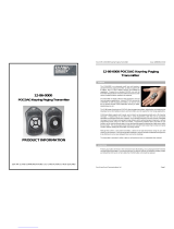
The unit can also be reset by depressing SW1 through the hole provided on the lower
endplate (see Diagram 1 below).
+
-

PRX4 & PRX4SERL Four Zone Receiver Decoder
Ref: RX4USER Page 8 of 8 Issue 1
Specification
Power Input: 12V to 13.8V dc max @ 0.5A
Power Consumption
Standby (relays off, no serial port) 28mA
Standby (relays off, serial port connected) 38mA
Active serial decoder 63mA
Active all relays 250mA
Signal Format POCSAG FSK NRZ (Normal or Inverted)
Frequency (fixed crystal) In the range 440 –470MHz
Frequency Stability +/- 10ppm
Channel Spacing 12.5 or 25KHz
Frequency Deviation +/- 4.5KHz
Over Air Baud Rate (fixed programmable) 512 or 1200 bps
Sensitivity Maximum
512bps 6µV/m
1200bps 7.5µV/m
Selectivity >52dB
Image Rejection >52dB
Spurious Rejection >60dB
Intermodulation >52dB
Relay Contact max rating 0.5A @ 125V ac, 1A @ 60V dc
Serial Port RS232
Serial Configuration N, 8, 1
Serial Port baud rate 9600
E & OE. Scope’s policy is one of continuous development and specifications are subject to change without notice
/