
Scope Marketing (Communications UK) Ltd, The Scope Complex, Wills Rd, Totnes, Devon TQ9 5XN
Tel: +44 1803 864569 Fax: +44 1803 863716
UHFAMP
UHF Power Amplifier MK2
UHFAMP
Installation & User Manual
Scope CommsScope Comms

UHF Amplifier AMP1-10
AMPUS/1 1 06/98
UHF Power Amplifier Model AMP1-10 MK2
Overview
This amplifier is designed to increase the operating range of an already correctly installed
system. In such a system the need for a well sited transmitting aerial should previously have
been addressed. The amplifier is not intended as a substitute for an indifferent, poorly located
aerial. In this context, we would strongly advise not to connect a simple quarter wave antenna
directly to the ‘N’ type output connector, as this will inevitably produce a strong local radiated
field, which is quite capable of causing interference to other equipment in the vicinity.
Note! This system requires a valid Radiocommunications Agency licence for operation in the
UK. It is the user’s responsibility to apply for this licence on form RA5.
Warning! Alteration or modification to any part of this equipment, without the prior written
consent of the manufacturer, will invalidate all Approvals and Warranties attaching to the
equipment. Further liability for the operation of the equipment, under the applicable law, will
pass to the user, who will absolve the manufacturer of any further responsibility for it’s correct
operation and use.
Installation
The output from the amplifier should be fed, via good quality coaxial cable, to a dipole or
beam aerial mounted high on a mast and clear of local obstructions. A minimum cable
specification is RG213 or UR67, and for runs longer than ten metres, helical membrane
(Heliax) cables are worth considering. At high frequencies, poor quality cable and associated
plugs and sockets incur high losses, and quickly negate the theoretical improvements in system
performance which a power amplifier might otherwise bring.
The following example is presented as an illustration of potential system losses. At 460 MHz
standard RG213 or UR67 cable loses 1 decibel - approximately 20% - of the incident power
for every 5 metres of length, and 15 metres (50 feet) loses 3dB. This means that if you start
with 10 watts out of the amplifier, you will get only 5 watts at the far end of 15 metres of
RG213 cable! These loss figures apply only to cable in a new, dry condition. Note that word
dry, because once moisture is allowed to enter the ends of the cable it will corrode the copper
conductors, particularly the outer braid, and thereby raise the loss to the point where the cable
looks like a reasonable dummy load, soaking up most of the transmitter power. It follows that
only good quality watertight, ‘O’ ring sealed connectors should be used. Unsealed crimped
connectors are a false economy and will result in the system failing in the longer term.
At radio frequencies signal currents flow only very near to the surfaces of electrical
conductors, a phenomenon which is known as skin effect. This means that the surface
resistivity of the cheaper nickel plated and chromium plated connectors makes a significant
contribution to the losses. For this reason we would advise to use the better quality silver
plated N series connectors.

UHF Amplifier AMP1-10
AMPUS/1 2 06/98
UHF Power Amplifier Model AMP1-10 MK2
Installation
For the DC powered unit, connect the power lead provided between the transmitter unit and
Amplifier module using the 2 pin lockable connectors located on the end chassis plates of the
respective units (these are polarised to avoid reverse connection).
Similarly, connect the RF input lead attached to the Amplifier module to the BNC connector
on the transmitter unit.
Do not attempt to increase the length of either the DC power cable or the RF input lead as this
may severely reduce the output power of the Amplifier.
For the mains powered unit, fit the mains lead into the IEC socket on the base of the unit and
connect the RF input lead as above.
The Amplifier module can be wall mounted using the fixing holes provided in the rear chassis
plate. To access these, remove the two cross-headed screws from the front cover (DC model)
or slacken the four cross-headed screws on the end plates (mains model) and lift off the cover.
Do NOT use the chassis as a drilling template, the vibrations may cause irreparable damage to
the electronic circuitry. Please also note that the unit is only intended for indoor installation
and as such should be mounted in close proximity to the transmitter unit (this is limited
anyway by the fixed length of the RF input cable).
Note: when installing the mains powered model, ensure the battery is fitted and
connected before operating the unit. Similarly, for the DC powered unit, ensure the
battery in the ConneXions unit is fitted and connected prior to operation.
Operation
The Amplifier is automatically switched into operation when the host unit transmits and
therefore requires no further user intervention.
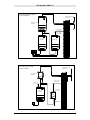
See diagrams on page 3 for typical examples of installation.

UHF Amplifier AMP1-10
AMPUS/1 3 06/98
ConneXions
Transmitter
Mains powered UHF Amplifier:
Typical Installation
Alternative in-line
Installation
UHF Amplifier
External wall mounted
dipole antenna
E
RG213 or UR67
Coaxial Cable
'N' Connector
(silver plated)
RF Out
ConneXions
Transmitter
DC powered UHF Amplifier:
Typical Installation
Alternative in-line
Installation
Power Inlet
12 to 13.8 V dc
'N' Connector
(silver plated)
UHF
Amplifier
RG213 or UR67
Coaxial Cable
External wall mounted
dipole antenna
E
Power Outlet
13.8 V dc
RF Out
-
 1
1
-
 2
2
-
 3
3
-
 4
4


Ask a question and I''ll find the answer in the document
Finding information in a document is now easier with AI
Related papers
-
scope AMP1-10 MK2 Installation & User Manual
-
scope DL4ACLUSA Owner's manual
-
-
-
-
-
-
-
-
Other documents
-
Weidmuller UR67-MP-HP-8DIDO-12-60M User manual
-
Maxview MXR0010 Operating instructions
-
-
-
-
-
EMS 5000 FirePoint Transponder User guide
-
-
Fusion INTELPage IP 5 User manual
-
dBTechnologies TOURING RACK MOVING D Owner's manual