Page is loading ...

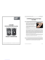
12-62-0000
Paging Transmitter
PRODUCT INFORMATION
Sea Air and Land Communications Ltd, PO Box 76237, 10 Magdala Place, Christchurch, New Zealand
12-62 SYNTHESIZED NRZ TRANSMITTER USER’S MANUAL Issue 1262UG 1011
Sea Air and Land Communications Ltd Page 1
12-62 POCSAG
PAGING TRANSMITTER
1.0 DESCRIPTION
The 12-62 is a 138 - 174 MHz (VHF) or 427.5 - 475 MHz (UHF) 4 watt POCSAG
paging transmitter with an in-built encoder. All parameters are programmable such as:
frequency, power output, deviation, POCSAG or NRZ data transmission.
The unit can be controlled via a USB port or an RS232 serial interface to provide
numeric, alphanumeric and tone-only POCSAG encoding. This enables a user to call
a pager (over 2,000,000 codes), append an appropriate priority level (1 of 4), and add
a numeric or alphanumeric message.
The 12-62 supports multiple message queuing, and will queue up to eight 240
character messages, or as many smaller messages that will fit into the available
memory buffer (up to 80). Pre-defined input messages are limited to a maximum
length of 40 characters which may be configured using the Salcom programming
software. Control via the USB or Serial port is achieved using ASCII character
commands.
The unit supports 4 discrete inputs with a different pre-programmed message on high
and/or low transition, plus voltage detection messages on the power input.
The inputs can be configured for a number of options. Provision to transmit a
message more than once and variable time between transmissions are catered for.
The USB port or the RS232 serial port can be used to initiate paging transmissions
using the SALCOM propriety protocol, Paging Entry Protocol (PET) or Telocator
Alphanumeric Protocol (TAP) PG1 protocol. These ports can be used concurrently
making it possible to connect a telephone interface unit and still initiate paging
transmissions via the USB port.
Over temperature cutout: If the transmitter operates for extended periods in a hot
environment, a protective thermal cutout may operate to reduce the output power to a
safe level. It will reset when the unit temperature has fallen to below 70 deg.
Transmitter Duty cycle: The transmitter duty cycle is rated as 50% with a max ‘on’
time of 5 minutes. Higher duty cycles may be possible. Contact Salcom for advice.

12-62 SYNTHESIZED NRZ TRANSMITTER USER’S MANUAL Issue 1262UG 1011
Sea Air and Land Communications Ltd Page 2
2.0 WARRANTY
Our Products are warranted for a period of 12 months from date of purchase against
faulty materials and workmanship. Should any fault occur the unit should be returned
to the vendor, freight pre-paid. Please include a description of the fault to assist with
prompt return. Any unauthorized alterations or repairs will invalidate the warranty.
3.0 DISCLAIMER
All information provided in this document is carefully prepared and offered in good
faith as a guide in the installation and use of the 12-62. Installers must ensure that the
final installation operates satisfactorily within the relevant regulatory requirements.
We accept no responsibility for incorrect installation. We reserve the right to change
products, specifications, and installation data at any time, without notice.
4.0 MECHANICAL DESCRIPTION
The 12-62 is enclosed in an extruded aluminium box. The end-plates unscrew and
the lid slides off to allow access to the component side of the pcb. The complete pcb
can then be slid out of the case if required, the heatsink relies on a light pressure
contact with the case for heat dissipation, The case has four holes for mounting the
unit. The 12-62 must be mounted away from sources of heat, damp or vibration.
5.0 INSTALLATION
The power supply is connected via P1, green power connector to +13.8 Volts and
Ground. The supply input is protected against reversed connection.
Radiation Hazard: Important! To comply with FCC Controlled /Occupational
Exposure Limits, the aerial must be positioned or mounted to operate at least 0.2
metre away from Occupational Staff and 0.5 metre away from the General Public. Use
only supplied aerial.
It is recommended to site the aerial a few metres away from the 12-62 to avoid the
possibility of RF feedback causing problems with the transmitter operation. An outside
aerial is preferable and will provide better radio coverage. The aerial connection is via
the BNC connector, and should present a nominal load of 50 S, with a VSWR of
better than 1.8:1.
External indicators consist of a power indicator GREEN LED, normally flashing ON
once per second to indicate healthy microcontroller operation.
12-62 SYNTHESIZED NRZ TRANSMITTER USER’S MANUAL Issue 1262UG 1011
Sea Air and Land Communications Ltd Page 3
After a debounce period, the green LED will flash rapidly if the low supply detector is activated.
The RED LED will indicate when the unit is transmitting. A flashing RED LED indicates the unit
cannot transmit as either the synthesiser is out of lock, the 12-62 is critically hot or an internal
fault has been detected.
S2 and S10 Connections
S2 Connections:- S10 Connections:-
Pin 1 Ground Pin 1 PTT OUT, 50mA max.
Pin 2 Interrupt Pin 2 GROUND
Pin 3 SCL Pin 3 Discrete Input 4
Pin 4 SDA Pin 4 Discrete Input 3
Pin 5 RS232 Tx Pin 5 Discrete Input 2
Pin 6 RS232 Rx Pin 6 Discrete Input 1
Pin 7 PTT Input for NRZ operation
Pin 8 Modulation Input for NRZ operation
6.0 OPERATION
The 12-62 can transmit 3 types of POCSAG message, with any one of 4 function
levels:
• Alphanumeric transmissions. Message can contain any alphanumeric ‘ASCII’
character.
• Numeric transmissions. Message contains only Numeric characters and some
symbols.
• Tone Only transmissions (Alphanumeric or numeric with no message)

12-62 SYNTHESIZED NRZ TRANSMITTER USER’S MANUAL Issue 1262UG 1011
Sea Air and Land Communications Ltd Page 4
6.1 Alphanumeric transmissions
Messages can contain any alphanumeric character. The 12-62 will accept the
standard ASCII 7 bit character set.
6.2 Numeric transmissions
Messages can contain numeric characters and some symbols.
These can convey a telephone number, or other numerically coded information.
The transmitted message is shorter, and therefore there is a smaller chance of
errors received by the pager.
The numeric character set is as follows: 0 1 2 3 4 5 6 7 8 9 [ ] - U <space>
6.3 Tone Only transmissions
Any numeric or alphanumeric paging message without an actual text message
is also considered ‘Tone Only’. A function level will control the number of
beeps on the receiver (four different function levels can be sent).
7.0 INITIATING TRANSMISSION
There are four ways of initiating a paging message transmission:
(1) Using the external discrete inputs (action)
(2) Supply detector threshold (action)
(3) Watchdog (action)
(4) RS232 Serial commands
An action is defined as a paging message, RIC (Receiver Identification Code or
capcode) and flags. Flags are discussed in the PSD (product support disk) section.
7.1 External Discrete Inputs
An action can be initiated from the 4 external inputs with an input transition to
LOW (connection to GND) and/or HIGH (input floating or connection to >+3.5v).
7.2 Low supply message
After a debounce period, the low-supply detector can initiate an action for both
“supply going high” and “supply going low”conditions.
7.3 Watchdog
The watchdog feature will initiate an action after a predetermined period. The
watchdog also optionally allows the transmission of the current state of selected
inputs (including supply level).
7.4 Using the RS232 Serial Commands
Serial commands can be “manually” issued to an 12-62 using a terminal
program such as PROCOMM or Hyper-terminal.
Tone only, numeric and alphanumeric pagers can be called using serial
commands. These commands will be processed in parallel with other inputs
actions for transmission. Some basic commands are described in section 8.0.
12-62 SYNTHESIZED NRZ TRANSMITTER USER’S MANUAL Issue 1262UG 1011
Sea Air and Land Communications Ltd Page 5
8.0 SALCOM PROTOCOL
Salcom protocol takes the basic form: PPXXXXXXXsLsMMMMMM<CR>
Where:
Pis either CA (512 baud alpha), CN (512 baud numeric), ca (1200 baud
alpha), or cn (1200 baud numeric).
Xis a 7 digit RIC code.
sis a space.
Lis a digit (1 to 4 beep level).
Mis the message payload (up to 240 characters).
<CR> is a carriage return (enter key).
CA
Usage: CA<pager#>[<space>]<level>[<space>]<message><CR>
Description: Call alphanumeric pager
Example: CA1119358 1 Please return to reception<CR>
Response: CA11193581<CR><SPACE>Page Sent<CR><LF>
CN
Usage: CN<pager#>[<space>]<level>[<space>]<message><CR>
Description: Call numeric pager
Example: CN1119358 1 777<CR>
Response: CN11193581<CR><SPACE>Page Sent<CR><LF>
RES
Usage: RES<CR>
Description: Reset 12-62 microcontroller
Example: RES<CR>
Response: SALCOM 12-62-0000 VX.XX<CR><LF>
SN?
Usage: SN?<CR>
Description: Retrieve unit serial number and firmware revision
Example: SN?<CR>
Response: SALCOM 12-62-0000 VX.XX 5122345<CR><LF>
8.1 Error Codes/Reports
ER1 SYNTAX You entered an invalid command
ER3 OPERND You entered a valid command with invalid values
ER6 BUSY 12-62 is too busy to process the entered command, try again
later.
ER7 OVERTEMP 12-62 is critically hot, transmission not possible until cooler.

12-62 SYNTHESIZED NRZ TRANSMITTER USER’S MANUAL Issue 1262UG 1011
Sea Air and Land Communications Ltd Page 6
9.0 TROUBLE SHOOTING
The following table may help in problem solving where necessary.
Fault Check
No illumination of Green LED Bad power supply connection
Input activated but no transmission PSD configuration incorrect
Unit transmits but nothing received Poor aerial. Wrong frequency, RIC, baud-rate. Power
too low. Unit too hot. Too much vibration
No RS232 serial communication Comport connections, baud-rate 9600 no parity, eight
data bits, one stop bit
Red LED flashes rapidly VCO out of lock, unit too hot or internal fault detected.
Connecting a serial lead to the 12-62 will allow the
nature of the fault condition to be determined.
Green led flashes rapidly Low supply detector threshold
Unit starts, but does not complete
transmission
Poor supply volts, RF interference.
10.0 PROGRAMMING
10.1 Installing the VCP USB Driver
To use the USB port to communicate with the 12-62, a Virtual Com Port
driver must be installed on the PC.
To install the Silicon Laboratories USB driver, run the driver installer
CP210x_VCP_Win2K_XP_S2K3.exe provided on the supplied PSD CD and
follow the on screen instructions. Once the driver is installed, an additional
COM port will be available via the Salcom PSD programming software.
VCP USB driver updates are provided periodically by Silicon Laboratories
and may be downloaded free of charge from https://www.silabs.com/support.
10.2 Preparations for Connecting the Programming Software
To change the field programmable options, the unit must be connected to a
PC running the 12-62 PSD programming software in Windows XP via either
the preferred USB port S8 (using the supplied USB mini cable), or the
standard serial port S2. To use the USB connector, the supplied virtual COM
port USB driver must be installed
Note: To make up a serial cable, the S2 connections are shown on page 3.
Alternatively purchase an optional Salcom serial programming cable.
12-62 SYNTHESIZED NRZ TRANSMITTER USER’S MANUAL Issue 1262UG 1011
Sea Air and Land Communications Ltd Page 7
The 12-62 must be powered during programming, +13.8V to power terminals.
Ensure that the 12-62 PSD has the correct com port selected. Once correctly
configured perform the following:
1 Press connect. The status at the bottom of the 12-62 PSD will indicate
if successfully connected.
2 Press the read button, or load a PSD configuration file. This will load all
settings of the 12-62, which is required before any changes can be
programmed. The 12-62 PSD will provide feedback if the user selected
operations are successful.
10.3 Using the Programming Software
The 12-62 PSD allows the user to configure the following characteristics:
> Input actions, watchdog, low supply detector and POCSAG transmission
settings
> Pre-defined messages
> RF frequency and output power
> 99 pager numbers for use with the Salcom 12-36 telephone interface.
Once the program is running, the opening screen appears . Use the mouse to
select the configuration fields for each feature.

12-62 SYNTHESIZED NRZ TRANSMITTER USER’S MANUAL Issue 1262UG 1011
Sea Air and Land Communications Ltd Page 8
10.4 PSD Input Configuration
All inputs may be configured in a similar fashion, including supply voltage
monitoring. The input drop down box provides support for the 4 inputs
available on S10.
The battery input is at the very bottom of the input list. Each input may have a
message defined for both a high and low state. Input parameters may be
configured as follows:
Pager type: Numeric or Alpha numeric. Tone only pagers are supported by
ensuring that the message field is left blank.
Beep Level: Page beep levels 1-4.
RIC Code: Pager ID. Valid Codes are:
0000008 to 2007663
2007672 to 2045055
2045064 to 2097143
0000000 may be used as a “drop” code. This may be used for the watchdog
when the watchdog is used, but a watchdog message is to be suppressed.
Message: User message, up to 40 characters in length.
Transmission Count: How many times that message will be sent if triggered.
Enabled: When selected, the configured message will be sent when triggered.
Resend with Watchdog: When the watchdog is enabled, the input message
will be sent periodically as configured if in the enabled state.
Initial Input State: Input messages are sent when transitioning to the enabled
state. If on start-up “Current” has been selected the current input state is read,
so that the input message will not be sent on start-up.
If “High” is selected, the input on startup is assumed to be in the high state, so
when found to be low (if this is the case) the transition will result in a message
being sent (if enabled). If “Low”, the opposite will occur, the input is assumed to
be low on startup, the transition to high resulting in message being transmitted
(if enabled, and the input is in the high state).
10.5 PSD General configuration
Selecting Options->General will display the general configuration screen as
shown overleaf. The following items may be set here.
12-62 SYNTHESIZED NRZ TRANSMITTER USER’S MANUAL Issue 1262UG 1011
Sea Air and Land Communications Ltd Page 9
Baud Rate: Changing this setting will result in all configured input messages to
be sent at the selected baud rate (512 or 1200 Baud).
Note: baud rate changes are not applied to serially generated Salcom protocol
messages.
Protocol: Allows the serial protocol to be changed
Input Debounce: The time delay between the input being triggered and the
message being sent.
Enable 12-36 Support: Enabling 12-36 support will allow the Salcom 12-36-
0000 telephone interface to be configured. Configuration options will become
available through the options tab (refer to 10.7: PSD 12-36 Support).
Invert Tx data: Internally generated data is inverted when Internal modulation
is selected. The Invert Tx Data option is unavailable when external modulation
is selected.
Resend Delay: When an input has been configured with a transmission count
greater than 1, then the resend delay is the delay in seconds before sending
the message again.
Max On Air: When the 12-62 is transmitting, this setting controls how long the
transmitter may be continuously on air. When this period of has been
exceeded the transmitter ceases transmission and will remain off air for the
duration defined by the Min OFF Air setting. This setting has no effect when
external modulation has been selected.

12-62 SYNTHESIZED NRZ TRANSMITTER USER’S MANUAL Issue 1262UG 1011
Sea Air and Land Communications Ltd Page 10
Min Off Air: When the 12-62 has exceeded the max on air continuous
transmission time, the Min OFF Air setting controls how long the transmitter will
remain powered down before allowing transmission to continue.
Lead In: The lead in defines how long the transmitter carrier will be present
before data transmission commences.
Lead Out: The lead out time controls how long the transmitter will remain on
air after data transmission has finished.
Frequency: Configures the transmission frequency. Note that the selected
frequency must be evenly divisible by the channel spacing.
Channel Spacing: Defines the frequency step resolution.
Unit Power Level: The power level to transmit at. Note that the power will be
reduced when the 12-62 exceeds 70 degrees.
Deviation: How much the selected frequency deviates by when transmitting
data. Note the custom setting is not to be used unless the 12-62 has been
factory set to support this option.
Modulation: If external modulation has been selected then no serial or input
controlled messages will be sent, data transmission is solely controlled by the
PTT and Modulation inputs on connector P2. When internal modulation is
selected then the PTT and modulation inputs do not serve any purpose.
Sent Response: Controls the serial response when a page has been
transmitted. Historically “Page Sent” would be sent by Salcom products to the
serial port to provide a controlling application with feedback that another
message may be submitted for transmission. Since the 12-62 may queue
many messages “Page Sent” may not describe sufficiently which page has
been transmitted. Selecting “[Sent] + Message” will allow feedback to the user
which message has been transmitted, but may introduce backwards
compatibility problems with applications supporting other Salcom products.
Selecting “Custom” will allow any user defined response up to 40 characters in
length. Selecting “None” will result in no serial feedback on completion of a
message transmission.
10.6 PSD Reset Options
Selecting Options-Reset to Factory Defaults will allow the user to restore the
12-62 to it’s original factory state. This option will not affect any factory
calibrated settings.
10.7 PSD Configuration files: The current 12-62 configuration can be saved
using File-Save. Previously saved configuration files can be loaded and
edited with, or without a 12-62 connected.
12-62 SYNTHESIZED NRZ TRANSMITTER USER’S MANUAL Issue 1262UG 1011
Sea Air and Land Communications Ltd Page 11
10.7 PSD 12-36 Support: To use the 12-62 with the Salcom 12-36 telephone
interface, Salcom protocol must be selected. Once selected, 12-36 support
can be enabled by selecting Options->General->Enable 12-36 support. When
enabled, the “Preset Messages” and “Pager Database” pages will be available
under Options->12-36 Support.
11.0 SPECIFICATIONS
Power Supply +11.5 V to 15.2 V nom 13.8 V
RF Frequency VHF: 136-174MHz UHF: 427.5-475 MHz
Switching Range Full 47.5MHz with no tuning
Channel Spacing 12.5 KHz or 25 KHz
Output Power 7 settings, 50mW to 4W ± 1 dB 50S
Input Current Standby : 40 mA Transmit: 1.2A approx
Modulation Carrier FSK with NRZ data
Deviation ±2.25kHz or ±4.5kHz
Baud rate 512, 1200 Baud
Message format POCSAG
Spurious Outputs -37dBm or less
Serial input/output S2, pins 5, 6, RS-232 (DCE), 9600 baud
no parity, 8 data bits, 1 stop bit
Serial paging command protocols SALCOM proprietary, PET (On Request)
Discrete inputs
Other Inputs
S10, pins 3-6, ground to activate. Pulled up to +12v (47K),
PTT on S10 pin 7, ground to activate.
External Modulation on S10, pin 1. 0-5V ±1V
Discrete output PTT Output, S10 pin 1, sinks <50mA.
Case Dimensions 155 x 101 x 30mm
Type Approvals AS/NZS4769, EN 300 224, FCC Pt 90
Transmit duty cycle Up to 100%
SEA AIR & LAND COMMUNICATIONS LTD
10 Magdala Place, Middleton, Christchurch 8024,
PO Box 76237 Northwood 8548, Christchurch, New Zealand
P: (03) 379-2298 F: (03) 365-1580 E: [email protected]
Visit us at www.salcom.co.nz
/