Page is loading ...

1
TeamWork
®
400 Kit • Installation Guide
TeamWork 400 Kit
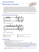
The TeamWork 400 kit consists of an HDMI switcher, system controller, Cable Cubby
®
, and cables packaged together as a
complete system that, in most cases, requires no conguration.
SW4 HD 4K PLUS
0.5A MA
X
POWER
12V
1
2
3
4
LAN
C T
C T
+V
1
2
C T C T
3
4
Tx
Rx
G
RS-232
INPUTS
OUTPUT
REMOTE
100-120V 50/
60Hz
US
OUTPUT
G
Tx R
x
COM
IR/S
1 2 3 G
DIGIT
AL
I/O
P
WR OUT = 6
W
eBUS
+V +S
-S
G
S G
LAN
IPCP PRO PCS1 xi
100-240V ~
1
0A M
AX
50-60Hz
INPUT
100-240V ~ 10A
MA
X
50-
60Hz
Extron
IPCP Pro PCS1 xi
IP Link Pro
Power and Device
Control Processor
Extron
SHARE
Extron
Cable Cubby 1202
Furniture Mountable
Cable Access Enclosure
Regional Sales
0
30
60
90
120
150
SOU
T
H
N
O
RTH
EAST
WEST
RS-232
Control Cable
Flat Panel
AC Cord
Adapter
Extron
HDMI Pro Cable
HDMI Video
Flat Panel
Display w/ Integr
ated
Speakers
Extron Show Me Cables
C
A
BLE CUBBY
Regional Sales
0
30
60
90
120
150
SOUTH
NORTH
EAST
WEST
Contact Closure
& Tally
Extron
SW4 HD 4K PLUS
Four Input 4K/60
HDMI Switcher
The diagram above shows a typical TeamWork 400 application. The input devices (laptops and a tablet) connect to the switcher,
using Show Me
®
cables. The Show Me cables allow the user to select the active input on the switcher.
A control cable connects the RS-232 ports on the switcher and the system controller.
The system controller powers the display on and off. The system controller has been congured so that when a video signal is
detected on any of the switcher inputs, the display is powered on. A 30 second timer is started when no signal is detected on
any of the switcher inputs. If an active source is detected before the timer expires, the display remains on and the timer is reset. If
30 seconds pass without an active signal, the system controller powers off the display.
The TeamWork kits work, as described, without further software conguration. If you need to change the behavior or operation of
the system, you must congure the system controller (see the IPCP Pro xi Series User Guide at www.extron.com).

TeamWork 400 Kit • Installation Guide (Continued)
2
Features
• Standard systems support groups of up to four users.
• Standard systems contain a complete turnkey package that includes cables, switcher, system controller, and CableCubby
enclosure.
• System controller pre-loaded with Global Congurator that requires no further adjustment.
• Works with most commercially available at panel displays, laptops and tablets.
• HDCP compliant.
• Section 508 compliant.
Kit Components
When your kit is delivered, check that all the components are present.
TeamWork 400 Kit
TeamWork 400
HDMI switcher 1 (SW4 HD 4K PLUS, 4 input)
System controller 1 (IPCP Pro PCS1 xi)
Cable Cubby 1 (Cable Cubby 1202)
Power modules (included with Cable Cubby) 1
HDMI Show Me cables 4
HDMI cable 1
Switcher control cable 1
4-cable Cable Cubby Bracket Kit 1 pair
Installation Guide TeamWork 400 Kit Installation Guide

3
Display Requirements
The TeamWork system is designed to work with most brands and models of at panel displays available worldwide. For optimum
performance, consider the following when selecting the displays for your TeamWork installation. The display should be tested
thoroughly prior to installation or mass deployment of TeamWork systems.
Power attributes — The system works by controlling AC power to the display. When the display is in the ON state with an HDMI
input selected, it must be able to power back ON to the same HDMI input when AC power is disconnected and reconnected.
If the display doesn’t behave this way, an alternate display should be used. Alternatively, you may need to control the display a
different way (i.e. RS-232, infrared, or via Ethernet) using a different type of Extron control processor.
Sleep mode — If the display has a Sleep Mode feature (sometimes called ‘auto sleep’), it must be disabled. Many displays have
an option to disable this within the menu settings.
Resolution — The TeamWork systems were designed for use with at panels having an HDMI input connector and having a
native resolution of 1080p. Many of the readily available consumer and professional displays support 1080p natively.
Audio — Audio from source devices is supported in the TeamWork system by routing it as an embedded audio signal to the
display for playback via integrated speakers. Most displays with HDMI inputs and integrated speakers work this way. Some
professional or commercial grade displays do not have integrated speakers and do not support audio playback. Typically, source
devices with HDMI output connectors embed audio onto the HDMI connector.
NOTES:
• Always check and test compatibility before installation. Some systems may require advanced conguration of the system
controller and require the display to be controlled by RS-232, Ethernet, or Infrared.
• Some displays support a lockout of local buttons. Extron recommends that, after setup, user accessible controls are
locked whenever possible. This ensures the display remains optimized for the TeamWork system.
SW4 HD 4K PLUS
0.5A MAX
POWER
12V
1 2 3 4
LAN
CTCT+V
12
CTCT
34
Tx Rx G
RS-232
INPUTS
OUTPUT REMOTE
OUTPUT
G
Tx Rx
COM
IR/S
1 2 3 G
DIGITAL I/O
PWR OUT = 6W
eBUS
+V +S
-S
G
S G
LAN
IPCP PRO PCS1
xi
100-240V ~ 10A MAX
50-60Hz
INPUT
100-240V ~ 10A MAX
50-60Hz
Ext
ron
HDMI
Switcher
Extron
IPCP Pro PCS1 xi
IP Link Pro
Power and Device
Control Processor
RS-232
Switcher Control
AC Power
1080p Native
Resolution Display
Display should have an HDMI
input and support embedded
audio.
For audio playback
display should have
integrated speakers
.
Teamwork Systems work
by controlling AC power
to the display.
Adapter
TeamWork systems require a display that returns
to the previous state when the power cord is
disconnected and then plugged back in.
How to check if a display is compatible:
1. Apply AC power to the display.
2. Turn the display ON.
3. Select the HDMI input.
4. Adjust the volume.
5. Unplug the display (remove AC power).
6. Re-apply AC power to the display.
If the display powers back up (to the ON state) and
to the same input and volume level, the display
works with the TeamWork system.

TeamWork 400 Kit • Installation Guide (Continued)
4
Installation
Install the Cable Pass-through Cassette Module and ShowMe Cables
Detailed instructions are in the Cable Cubby Setup Guide.
Extron recommends the layout shown to the right with cable
pass-through module to the left of the power module.
NOTE: The gure to the right shows the US power
module. Power modules for other countries look
different.
INPUT
(to source device)
Top of Cable Cubby
OUTPUT
(to switcher)
Bottom of
Cable Cubby
Share Button
Three-conductor
pigtail for contact
closure and tally
ATTENTION:
• The end with the button and LED connects to the input
devices and must come out of the top of the Cable
Cubby.
• Le bout avec le bouton et la LED se connecte
aux appareils d’entrée et doit ressortir du haut du
CableCubby.
• The end with the three-conductor pigtail connects to
the switcher and must come out of the bottom of the
Cable Cubby.
• Le bout avec le mini câble à trois conducteurs se
connecte au sélecteur et doit ressortir du bas du
Cable Cubby.
1. Assemble the cable pass-through cassette module as shown
in "Assemble Cable Module" in the diagram to the right.
2. Insert the cable cassette module into the Cable Cubby from
underneath and secure them in position with the provided
#4-40 Phillips head screws and star washers.
Install the Power Modules in the Cable Cubby
Insert the power module into the Cable Cubby from underneath
and secure the power modules in position with the provided
#4-40 Phillips head screws and star washers (see "Install Power
Module" in the diagram to the right).
WARNING: Possible electric shock: To ensure
good electric grounding, you must use the star
washers with the screws.
AVERTISSEMENT: Risque de choc électrique:
An d’assurer une mise à la terre correcte, vous
devez xer les modules d’alimentation au Cable
Cubby à l’aide de vis et de rondelles en étoile.
Power ModuleCable Pass-through Cassette Module
P
P
R
R
E
E
S
S
S
S
T
T
O
O
R
R
E
E
S
S
E
E
T
T
125V~50-60Hz 12A MAX TOTAL
power module
1
Secure the modules using
four of the provided
pan-head mounting scr
ews
and star washers.
2
1
2
5V~
50
-
60
H
z 12A M
A
X
TOTA
L
TOP
Cable Cubby 1202
Slide the cassette modules
into the Cable Cubby from
underneath.
1
Assemble Cable Module
Install Power Module
Insert Show Me
Cables into the
grommet plate.
Attach the Trim Plate
to the top of the module,
using the included
screws.
Attach the grommet
plate to the bottom
of the module, using
the included screws.
2
3

5
Mounting and Placement of System Components
Decide where to install your TeamWork system and where to place the individual components.
• The Cable Cubby should provide easy access for as many users as possible. Ensure that there is ample space for cables
under the table. Ensure that the edge on which the lid opens is correctly oriented.
• The system controller should be placed close to the display.
• The switcher should be placed close to the Cable Cubby.
Shown mounted with
optional Extron UTS 100/UTS 150
Under Table Shelf System.
Secure Show Me Cable
to Cable Cubby and create a
loop.
HDMI Video to Display
Extron
Cable Cubby
Cable Access Enclosure
HDMI Show Me
Cable
System Controller
Switcher
Power
Supply
AC Power To Display
SW4 HD 4K PLUS
HDMI SWITCHER
R
CONFIG
AUTO
SWITCH
SIGNAL
INPUTS
OUTPUT
HDCP
1 2 3 4
INPUTS
1 2 3 4
1080p Native
Resolution Display
R
OVER
LIMIT
E
B
L
ACT
1000
LINK
eBUS COMI/O IR/S
1
2
3
Tx
Rx
BREAKER
10
T
O
R
E
S
E
T
POWER
IPCP PRO PCS1 xi
Installing the Cable Cubby in the Table
Before cutting the table and installing the Cable Cubby, see the Cable Cubby Setup Guide (see www.extron.com).
ATTENTION:
• Ensure that the orientation of the Cable Cubby and the hole dimensions are correct before cutting the table.
• Assurez vous que la position du Cable Cubby et les dimensions du trou soient correctes avant de couper la table.
• After installation, secure the cables to avoid them becoming tangled (see the gure above).
• Après l’installation, sécurisez les câbles de façon à éviter qu’ils ne s’emmêlent (voir l’illustration au-dessus).

TeamWork 400 Kit • Installation Guide (Continued)
6
Cabling
SW4 HD 4K PLUS
0.5A MAX
POWER
12
V
1
2
3
4
LAN
C T
C T +V
1
2
C T C T
3
4
Tx Rx G
RS-232
IN
PUTS
OUTPUT
REMOTE
100-120V 50/60Hz
U
S
OUTPUT
G
Tx R
x
COM
IR/S
1 2
3
G
DIGITAL
I/O
P
WR OUT = 6W
eBUS
+
V
+S
-S
G
S G
LAN
IPCP PRO PCS1 xi
100-240V ~ 10A
MA
X
50-60Hz
INP
UT
100-240V ~
10A
MAX
50-60Hz
Extron
SHARE
Extron
Cable Cubby 1202
Furniture Mountable
Cable Access Enclosure
Regional Sales
0
30
60
90
120
150
SOU
T
H
N
O
RTH
EAST
WEST
Extron
IPCP Pro PCS1 xi
IP Link Pro
Power and Device
Control Processor
RS-232
Control Cable
Flat Panel
AC Cord
Adapter
Extron
HDMI Pro Cable
HDMI Video
Flat Panel
Display w/ Integr
ated
Speakers
Extron Show Me Cables
C
A
BLE CUBBY
Regional Sales
0
30
60
90
120
150
SOUTH
NORTH
EAST
WEST
Contact Closure
& Tally
2
1
3
4
5
6
6
Extron
SW4 HD 4K PLUS
Four Input 4K/60
HDMI Switcher
1
Connect the Show Me cables to the source devices.
2
Connect the Show Me cables to the switcher.
3
Connect the switcher to the display.
4
Connect the display to the system controller.
5
Connect the system controller to the switcher.
6
Connect power to the switcher and system controller.
NOTE: The power module shown on page 4 has two sockets on the top and two outlet cables underneath. The two outlet
cables are 2 feet (61 cm) and can be used to power the switcher and system controller of the TeamWork kit, if required.

7
HDMI Show Me Cables
The Extron Show Me cables are for use with Extron TeamWork systems. They feature a Share button for remote input source
selection and a control pigtail, which may be wired directly into Extron switchers with contact closure and tally outputs.
HDMI Show Me cable
INPUT
(to source device)
Top of Cable Cubby
OUTPUT
(to switcher)
Bottom of
Cable Cubby
Share Button
Three-conductor
pigtail for contact
closure and tally
1. Connect the input end of the Show Me cable to the source device.
2. Connect the HDMI output to the Extron switcher.
CTCT+V
12
CTCT
34
Tx Rx G
RS-232
REMOTE
SHOW ME CABL
E
SWITCHER END
(output)
Male HDMI connector
Three-conductor
pigtail for contact
closure and tally
Extron SW4 HD 4K PLUS Switcher (HDMI input)
BlackRed
Pigtail
Drain wire
(not used)
SW4 HD 4K PLUS
0.5A MAX
POWER
12V
1 2 3 4
LAN
CTCT+V
12
CTCT
34
Tx Rx G
RS-232
INPUTS
OUTPUT REMOTE
3. Connect the black (Tally Out) and red (Contact) pigtail wires as shown above. The number next to the Tally Out and
Contact pins must correspond to the video input on the switcher.
NOTES:
• The drain wire does not need to be wired to the switcher. The Show Me cables are grounded via the video
connectors.
• Do not connect the Show Me cable to the +V pin on the Extron switcher.
Press the Share button to switch the connected source to the main presentation display.
Pressing the Share button creates a momentary contact closure, which triggers the switcher to select the connected source
device. If a tally output is available, the button lights blue.
NOTES:
• The source device provides the +5 VDC supply voltage needed to illuminate the Share button. If the source device
does not supply this +5VDC, the Share button does not light. Some mobile devices do not provide the required
voltage to light up the button.
• Digital Show Me cables support embedded audio and CEC signals.

TeamWork 400 Kit • Installation Guide (Continued)
8
Connect the Switcher to the Display Device
Connect the switcher HDMI output to the HDMI input of the display device, using the provided cable. Do not use HDMI to DVI
adapters. If necessary, see the user guide for the display device.
Connect the Display to the System Controller
Connect the power cord from the display device to the power output receptacle of the system controller. TeamWork systems work
by controlling the AC power to the display.
Connect the System Controller to the Switcher
Connect the COM port of the system controller to the RS-232 port on the switcher with the provided control cable.
Switcher
(SW4 HD 4K PLUS)
3-pole connecto
r
(to switcher)
3-pole connector
(to system controller)
Switcher Control Cable
System Controller
(IPCP Pro PCS1 xi)
G
Tx Rx
COM
CTCT+V
12
CTCT
34
Tx Rx G
RS-232
REMOTE
Connect Power
The system controller uses an internal power supply. Connect the power cord to a wall outlet.
The TeamWork 400 systems use a 4 input switcher with a 12 VDC, 1.5 A power supply, which is provided with the
switcher.
ATTENTION:
• Do not connect the power supply to the SW4 HD 4K PLUS switcher until you have read the Attention
notications in the “Wiring the Power Supply” section of the SW HD 4K PLUS Series User Guide.
• Ne branchez pas le sélecteur SW4 HD 4K PLUS avant d’avoir lu la mise en garde dans la section « sources
d’alimentation » du SW HD 4K PLUS Series User Guide.
0.5 A MA
X
POWER
12 V

9
Testing the System
The TeamWork system has been pre-congured so that, once all the connections have been made and the devices are all
powered on, there should be no need of further conguration for the system to work. To ensure that the system has been set up
correctly, follow these steps:
1. Power on the equipment:
• Source devices
• Switcher
• System controller (IPCP Pro PCS1 xi)
2. Press the POWER button (
1
) on the front panel of the system controller.
The LED (
2
) lights green when power is being supplied to the attached
output device.
3. Turn on the display and conrm that the display is receiving power.
4. Go to the menu for the display and disable the sleep mode feature. If
necessary, see the display user guide.
5. Press the POWER button on the power controller. The LED should go out
and the display should be turned off.
6. Connect one of the Show Me cables to a video source, such as a laptop.
7. Press the Share button on that cable. If the source device is providing a
video signal, the LED on the ShowMe cable lights blue and the display automatically turns on.
8. Connect a second Show Me cable to a second video source.
9. Repeat step 7 to verify that the second source device is providing a video signal and it is the output signal from the switcher.
When the button on the second Show Me cable is pressed, the LED lights blue and the LED on the rst cable is switched off.
10. Disconnect all the Show Me cables from the source devices.
After about 30 seconds without an input signal, the display should turn off.
11. Connect a Show Me cable to a source device and press the Share button on that cable.
As soon as an active video signal is detected, the display should automatically turn on.
Troubleshooting
No Image on the Display:
Cause 1 — There is a problem with the source device:
Solution — Verify that the source device is powered on and outputs an active signal.
Cause 2 — Cable connections are incorrect:
Solution — Verify that the HDMI output cable from the switcher is connected to the current HDMI input of the display.
Cause 3 — Display is off:
Solution 1 — Verify that the display is in the on state.
Solution 2 — The TeamWork system turns the display on and off by controlling the ACpower. If the display has a Sleep Mode
feature, this feature must be disabled to prevent the display from accidentally powering off.
Cause 4 — The display has a problem:
Solution — Verify that the display functions correctly.
Cause 5 — The display cannot show video at the incoming resolution:
Solution — The EDID settings on the switcher may need to be changed. Refer to the SW HD 4K Series User Guide (see
www.extron.com) or contact an Extron Support representative at www.extron.com/company/contactus.aspx.
R
OVER
LIMIT
E
B
L
ACT
1000
LINK
eBUS COM I/O IR/S
1
2
3
Tx
Rx
BREAKER
10
T
O
R
E
S
E
T
P
R
E
S
S
POWER
IPCP PRO PCS1 xi
1
2

10
TeamWork 400 Kit • Installation Guide (Continued)
68-2400-01 Rev. B
04 21
For information on safety guidelines, regulatory compliances, EMI/EMF compatibility, accessibility, and related topics, see the
Extron Safety and Regulatory Compliance Guide on the Extron website.
For information about replacing and disposing of batteries, see the IPCP Pro xi Series User Guide at www.extron.com.
© 2021 Extron — All rights reserved. www.extron.com
All trademarks mentioned are the property of their respective owners.
Worldwide Headquarters: Extron USA West, 1025 E. Ball Road, Anaheim, CA 92805, 800.633.9876
Show Me Button LEDs Stay Off When Pressed:
Cause 1 — The cable is not plugged into a source device that is producing an active video output signal:
Solution — Verify that the source device is on and producing an active signal.
Cause 2 — Contact or Tally wiring is incorrect:
Solution — See HDMI Show Me Cables on page 7 to ensure the contact and tally pins are correctly wired.
Cause 3 — The switcher is not powered on:
Solution — Verify that the switcher is powered on.
Cause 4 — Problem with Show Me cable:
Solution — Try connecting the video source to a different cable. If the second cable works correctly, there may be a problem
with the Show Me cable. Contact an Extron Support representative at www.extron.com/company/contactus.aspx.
Cause 5 — Problem with Switcher:
Solution — If none of the cables work correctly, there may be a problem with the switcher. Contact an Extron Support
representative at www.extron.com/company/contactus.aspx.
Cause 6 — The source device does not output +5V:
Solution — This is a problem with the source device. HDMI specications require pin 18 to carry a +5V output.
The Display Does Not Automatically Turn On:
Cause 1 — Incorrect wiring:
Solution — Verify that the RS-232 communication cable is connected properly between the IPLink Pro controller and Extron
switcher.
Cause 2 — There is no video signal present at Show Me cables:
Solution — Verify that an active signal is present at the input of any of the Show Me cables.
Cause 3 — IP Link Pro conguration is missing or corrupted:
Solution — Contact an Extron Support representative at www.extron.com/company/contactus.aspx.
Cause 4 — Display power is out of sync:
Solution — The display is in standby mode. Turn on the display using the remote or the physical power button.
Cause 5 — Display has sleep mode enabled
Solution — Go to the menu for the display and disable the sleep mode feature. Turn on the display using the remote or
physical power button.
The Display Stays On and Never Turns Off:
Cause 1 — Video signal is present at Show Me cables:
Solution — Verify that no active signals are present at the inputs of any of the Show Me cables. The TeamWork system is
designed to turn off the display only when no video signals are present.
/