Page is loading ...

User Guide
CTR 8
Switcher Accessories
Eight Input Contact Closure to RS-232 Control Module
68-2524-01 Rev. A
12 13

Safety Instructions
Safety Instructions • English
WARNING: This symbol, , when used on the product, is intended to
alert the user of the presence of uninsulated dangerous voltage within the
product’s enclosure that may present a risk of electric shock.
ATTENTION: This symbol, , when used on the product, is intended
to alert the user of important operating and maintenance (servicing)
instructions in the literature provided with the equipment.
For information on safety guidelines, regulatory compliances, EMI/EMF
compatibility, accessibility, and related topics, see the Extron Safety and
Regulatory Compliance Guide, part number 68-290-01, on the Extron website,
www.extron.com.
Instructions de sécurité • Français
AVERTISSEMENT : Ce pictogramme, , lorsqu’il est utilisé sur le
produit, signale à l’utilisateur la présence à l’intérieur du boîtier du produit
d’une tension électrique dangereuse susceptible de provoquer un choc
électrique.
ATTENTION : Ce pictogramme, , lorsqu’il est utilisé sur le produit,
signale à l’utilisateur des instructions d’utilisation ou de maintenance
importantes qui se trouvent dans la documentation fournie avec le
matériel.
Pour en savoir plus sur les règles de sécurité, la conformité à la réglementation,
la compatibilité EMI/EMF, l’accessibilité, et autres sujets connexes, lisez les
informations de sécurité et de conformité Extron, réf. 68-290-01, sur le site
Extron, www.extron.com.
Sicherheitsanweisungen • Deutsch
WARNUNG: Dieses Symbol auf dem Produkt soll den Benutzer
darauf aufmerksam machen, dass im Inneren des Gehäuses dieses
Produktes gefährliche Spannungen herrschen, die nicht isoliert sind
und die einen elektrischen Schlag verursachen können.
VORSICHT: Dieses Symbol auf dem Produkt soll dem Benutzer in der
im Lieferumfang enthaltenen Dokumentation besonders wichtige Hinweise
zur Bedienung und Wartung (Instandhaltung) geben.
Weitere Informationen über die Sicherheitsrichtlinien, Produkthandhabung,
EMI/EMF-Kompatibilität, Zugänglichkeit und verwandte Themen finden Sie in
den Extron-Richtlinien für Sicherheit und Handhabung (Artikelnummer
68-290-01) auf der Extron-Website, www.extron.com.
Instrucciones de seguridad • Español
ADVERTENCIA: Este símbolo, , cuando se utiliza en el producto,
avisa al usuario de la presencia de voltaje peligroso sin aislar dentro del
producto, lo que puede representar un riesgo de descarga eléctrica.
ATENCIÓN: Este símbolo, , cuando se utiliza en el producto, avisa
al usuario de la presencia de importantes instrucciones de uso y
mantenimiento recogidas en la documentación proporcionada con el
equipo.
Para obtener información sobre directrices de seguridad, cumplimiento
de normativas, compatibilidad electromagnética, accesibilidad y temas
relacionados, consulte la Guía de cumplimiento de normativas y seguridad de
Extron, referencia 68-290-01, en el sitio Web de Extron,www.extron.com.
Èíñòðóêöèÿ ïî òåõíèêå áåçîïàñíîñòè • Ðóññêèé
ÏÐÅÄÓÏÐÅÆÄÅÍÈÅ: Äàííûé ñèìâîë, , åñëè óêàçàí
íà ïðîäóêòå, ïðåäóïðåæäàåò ïîëüçîâàòåëÿ î íàëè÷èè
íåèçîëèðîâàííîãî îïàñíîãî íàïðÿæåíèÿ âíóòðè êîðïóñà
ïðîäóêòà, êîòîðîå ìîæåò ïðèâåñòè ê ïîðàæåíèþ
ýëåêòðè÷åñêèì òîêîì.
ÂÍÈÌÀÍÈÅ: Äàííûé ñèìâîë, , åñëè óêàçàí íà ïðîäóêòå,
ïðåäóïðåæäàåò ïîëüçîâàòåëÿ î íàëè÷èè âàæíûõ èíñòðóêöèé
ïî ýêñïëóàòàöèè è îáñëóæèâàíèþ â ðóêîâîäñòâå,
ïðèëàãàåìîì ê äàííîìó îáîðóäîâàíèþ.
Äëÿ ïîëó÷åíèÿ èíôîðìàöèè î ïðàâèëàõ òåõíèêè áåçîïàñíîñòè,
ñîáëþäåíèè íîðìàòèâíûõ òðåáîâàíèé, ýëåêòðîìàãíèòíîé
ñîâìåñòèìîñòè (ÝÌÏ/ÝÄÑ), âîçìîæíîñòè äîñòóïà è äðóãèõ
âîïðîñàõ ñì. ðóêîâîäñòâî ïî áåçîïàñíîñòè è ñîáëþäåíèþ
íîðìàòèâíûõ òðåáîâàíèé Extron íà ñàéòå Extron: www.extron.com,
íîìåð ïî êàòàëîãó - 68-290-01.
Chinese Simplified
Extro n www .extron.com
Extron68-290-01
Chinese TraditionalȞ ġĪ
Ļġ 㤕⭒૱к֯⭘↔ㅖ㲏ˈᱟ⛪Ҷᨀ䟂֯⭘㘵ˈ⭒૱⇬ޗᆈ൘㪇
ਟ㜭ᴳሾ㠤䀨䴫ѻ付䳚Ⲵᵚ㎅㐓ড䳚䴫༃DŽ
ġ㤕⭒૱к֯⭘↔ㅖ㲏ˈᱟ⛪Ҷᨀ䟂֯⭘㘵ˈ䁝ۉ䳘䱴Ⲵ⭘ᡦѝᴹ䟽
㾱Ⲵ઼㏝䆧˄ ㏝؞˅䃜 ᰾DŽ
ᴹ䰌ᆹޘᙗᤷሾᯩ䠍ǃ⌅㾿䚥ᆸǃ(0,(0)ᇩᙗǃᆈਆㇴഽ઼䰌ѫ乼Ⲵ䂣㍠䋷
䀺ˈ䃻☿㿭([WURQ㏢ㄉ˖www.extron.comˈ❦ᖼ৳䯡lj([WURQᆹޘᙗ㠷⌅㾿
䚥ᆸNJˈⓆࡷ㐘㲏DŽ
Japanese
www.extron.com Extron Safety
and Regulatory Compliance Guide P/N 68-290-01
Korean
넩韥뿭 閵뇑븽꾅ꩡ끞鷕陲끥뇑븽넍넭먩ꈑ놵驩꾅넽鱉
뇆덵鷍덵껿냵낹뾍뼑놹ꌍꈑ넭뼩ꩡ끞녅閵闅놹鷕낹뾍넩넽넁냹
陲隕뼞鱽鲙
넩韥뿭 閵뇑븽꾅ꩡ끞鷕陲끥녚ꟹ꿵뼝颍뇑險鷑뗺녅꾅驍꿵
넽鱉늱끉끩꾶ꗄ냕덵ꚩꯍ뇊ꟹ덵렝냹陲隕뼞鱽鲙
껽놹閵넩麑ꄱ넭鞑뇑늵ꯍ(0,(0)뿭쀍ꫦ뇆鞱ꫦ鞭ꍡ隕隵ꇝ뼢ꑞ꾅
鲵뼑녅ꫭ뼑驩끞냵([WURQ낮ꩡ넩뱭www.extron.com넍([WURQ껽놹ꗄ
鞑뇑늵ꯍ껽驩눥뼢냹뗭눥뼍겢겑꿙
www.extron.com
www.extron.com
www.extron.com
www.extron.com
www.extron.com
www.extron.com
www.extron.com
www.extron.com
www.extron.com

FCC Class A Notice
This equipment has been tested and found to comply with the limits for a Class A digital device,
pursuant to part15 of the FCC rules. The ClassA limits provide reasonable protection against harmful
interference when the equipment is operated in a commercial environment. This equipment generates,
uses, and can radiate radio frequency energy and, if not installed and used in accordance with the
instruction manual, may cause harmful interference to radio communications. Operation of this
equipment in a residential area is likely to cause interference; the user must correct the interference at
his own expense.
NOTE: This unit was tested with shielded I/O cables on the peripheral devices. Shielded cables
must be used to ensure compliance with FCC emissions limits.
For more information on safety guidelines, regulatory compliances, EMI/EMF compatibility,
accessibility, and related topics, see the “Extron Safety and Regulatory Compliance
Guide” on the Extron website.
Copyright
© 2013 Extron Electronics. All rights reserved.
Trademarks
All trademarks mentioned in this guide are the properties of their respective owners.
The following registered trademarks
®
, registered service marks
(SM)
, and trademarks
(TM)
are the property of
RGBSystems, Inc. or Extron Electronics:
Registered Trademarks
(®)
AVTrac, Cable Cubby, CrossPoint, eBUS, EDID Manager, EDID Minder, Extron, Flat Field, GlobalViewer, Hideaway, Inline, IPIntercom,
IPLink, Key Minder, LockIt, MediaLink, PlenumVault, PoleVault, PowerCage, PURE3, Quantum, SoundField, SpeedMount, SpeedSwitch,
System INTEGRATOR, TeamWork, TouchLink, V-Lock, VersaTools, VN-Matrix, VoiceLift, WallVault, WindoWall, XTP, and XTP Systems
Registered Service Mark
(SM)
: S3 Service Support Solutions
Trademarks
(
™
)
AAP, AFL (Accu-Rate Frame Lock), ADSP (Advanced Digital Sync Processing), Auto-Image, CDRS (Class D Ripple Suppression), DDSP
(Digital Display Sync Processing), DMI (Dynamic Motion Interpolation), DriverConfigurator, DSPConfigurator, DSVP (Digital Sync Validation
Processing), FastBite, FOXBOX, IP Intercom HelpDesk, MAAP, MicroDigital, ProDSP, QS-FPC (QuickSwitch Front Panel Controller),
Scope-Trigger, SIS, Simple Instruction Set, Skew-Free, SpeedNav, Triple-Action Switching, XTRA, ZipCaddy, ZipClip

Conventions Used in this Guide
Notifications
The following notifications are used in this guide:
ATTENTION: Attention indicates a situation that may damage or destroy the product or
associated equipment.
NOTE: A note draws attention to important information.
Software Commands
Commands are written in the fonts shown here:
^AR Merge Scene,,Op1 scene 1,1 ^B 51 ^W^C
[01] R 0004 00300 00400 00800 00600 [02] 35 [17] [03]
E X! *X1&* X2)* X2#* X2! CE}
NOTE: For commands and examples of computer or device responses
mentioned in this guide, the character “0” is used for the number zero and “O”
is the capital letter “o.”
Computer responses and directory paths that do not have variables are written in the font
shown here:
Reply from 208.132.180.48: bytes=32 times=2ms TTL=32
C:\Program Files\Extron
Variables are written in slanted form as shown here:
ping xxx.xxx.xxx.xxx —t
SOH R Data STX Command ETB ETX
Selectable items, such as menu names, menu options, buttons, tabs, and field names are
written in the font shown here:
From the File menu, select New.
Click the OK button.
Specifications Availability
Product specifications are available on the Extron website, www.extron.com.

vCTR 8 • Contents
Contents
Introduction............................................................ 1
About the CTR 8 ................................................ 1
Features ............................................................. 1
Panels and Cabling .............................................. 2
Front Panel Features ........................................... 2
Rear Panel Features and Cabling ........................ 2
Application Diagrams .......................................... 4
Remote Communication and Control ............. 6
Using Simple Instruction Set (SIS) Commands .... 6
Host-to-CTR 8 Communications .................... 6
CTR 8-Initiated Messages ............................... 6
Symbols Used in this Guide ................................ 7
Error Messages .............................................. 7
Command and Response Table for SIS
Commands ....................................................... 8
A/V Muting ......................................................... 8
A/V Mute Modes............................................. 8
LED Responses for Video Muting ................... 9
Updating Firmware ............................................ 10
Downloading and Installing Firmware Loader .... 10
Downloading CTR 8 Firmware .......................... 11
Installing Firmware with Firmware Loader .......... 11
Mounting ............................................................... 15
Tabletop Placement ...................................... 15
Rack Mounting ............................................. 15
Under-desk and Furniture Mounting .............. 15
Extron Warranty .................................................. 16

CTR 8 • Introduction 1
Introduction
About the CTR 8
The Extron CTR 8 control module provides contact closure input switching for most Extron
switchers with RS-232 capability. It allows simple push-buttons to remotely switch and
mute audio and video sources. The CTR 8 accepts up to eight contact closure inputs and
converts them to SIS serial commands that select the corresponding input on an Extron
switcher.
Features
• Eight contact closure inputs with tally allow remote switching and selection
status using simple push-button control.
• COM switcher port sends SIS commands to the Extron switcher for input switching
and muting.
• A/V muting allows the user to mute a switcher output by consecutively pushing the
same input button.
• +5 VDC output on each contact closure input is used to light an LED, indicating
input selection.
• Remote RS-232 port for remote control using Extron Simple Instruction Set (SIS)
commands.
• DC power input with loop-through allows one power supply to power the CTR 8
and an additional Extron device.

CTR 8 • Panels and Cabling 2
Panels and
Cabling
This section covers the following:
• Front Panel Features
• Rear Panel Features and Cabling
• Application Diagrams
Front Panel Features
CTR 8
12V
POWER IN
POWER OUT
RS-232
Tx
4
CGT+V
3
CGT+V
2
CGT+V
1
CGT+V
8
CGT+V
7
CGT+V
6
CGT+V
5
CGT+V
G
Tx Rx G
1.0A
MAX
1
Power LED — Lights green when the unit is receiving power.
1.0A
MAX
CONTACT IN / TALLY OUT COM
REMOTE
Power
Connectors
(see next page)
Contact inputs
with tally
(see next page)
Remote RS-232 port
(see page 4)
COM switcher port
(see page 4)
2 3
4
1
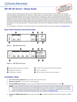
Figure 1. CTR 8 Front Panel
Rear Panel Features and Cabling
The following section covers rear panel features and cabling procedures. If mounting is
necessary before connecting cables, see the Mounting section on page 15.
ATTENTION: Turn all input and output devices off and unplug their power cords. Verify
that the CTR 8 is disconnected from the power source before proceeding.
CTR 8
12V
POWER IN
POWER OUT
RS-232
Tx
4
CGT+V
3
CGT+V
2
CGT+V
1
CGT+V
8
CGT+V
7
CGT+V
6
CGT+V
5
CGT+V
G
Tx Rx G
1.0A
MAX
1
Power LED — Lights green when the unit is receiving power.
1.0A
MAX
CONTACT IN / TALLY OUT COM
REMOTE
Power
Connectors
(see next page)
Contact inputs
with tally
(see next page)
Remote RS-232 port
(see page 4)
COM switcher port
(see page 4)
2 3
4
1
Figure 2. CTR 8 Rear Panel

CTR 8 • Panels and Cabling 3
a DC power input with loop through — Wire the external 12 VDC power
supply as shown in figure 3 and connect it to the two-pole captive screw
Power In connector.
SECTION A–A
Ridges
Smooth
Power Supply Output Cord
A
A
3/16”
(5 mm) Max.
Figure 3. Power Connection
The Power Out connector allows power to be looped to an Extron device
that uses +12 VDC voltage. Follow the same pin diagram above to connect a
device to the Power Out connector.
ATTENTION:
• Do not tin the wires. For best results and to reduce the risk of short circuits,
trim just 3/16 inch (5 mm) of the jacket from the wires. If it is any longer, the
exposed wires may touch, causing a short circuit between them. If it is any
shorter, the wires can be easily pulled out even if tightly fastened by the captive
screws.
• Always use a power supply supplied by or specified by Extron. Use of an
unauthorized power supply voids all regulatory compliance certification and
may cause damage to the supply and the end product.
• Unless otherwise stated, the AC/DC adapters are not suitable for use in air
handling spaces or in wall cavities. The power supply is to be located within the
same vicinity as the Extron AV processing equipment in an ordinary location,
Pollution Degree 2, secured to the equipment rack within the dedicated closet,
podium or desk.
• The installation must always be in accordance with the applicable provisions of
National Electrical Code ANSI/NFPA 70, article 75 and the Canadian Electrical
Code part 1, section 16. The power supply shall not be permanently fixed to
building structure or similar structure.
b Contact closure inputs with tally outputs — Connect contact closure source
devices to these 4-pole female captive screw connectors. Wire each connector as
shown in figure 4.
NOTES:
• For “Show Me” cables, the ground pin connection is optional.
• Do not connect “Show Me” cables to the +V pin.
CGT+V
Contact (C)
Ground (G)
Tally output (T)
T
ally voltage (+V)
Transmit (Tx)
Receive (Rx)
Ground (G)
Tx Rx
RS-232
G
Transmit (Tx)
Ground (G)
Tx
COM
G
Figure 4. Contact Input Wiring
• C = Contact input pin: Momentary closure of this pin to ground selects the
corresponding number input. Selection is triggered specifically at the moment of
closing, not opening.
• G = Ground pin
• T = Tally output pin: controls the LEDs on push buttons. When an input is
selected, only the tally corresponding to that input is active.
• +V = Tally voltage output pin (optional): provides the +5 VDC supply voltage
needed to illuminate tally LEDs.
POWER IN
POWER OUT
1.0A
MAX
1.0A
MAX
POWER IN
POWER OUT
1.0A
MAX
1.0A
MAX

CTR 8 • Panels and Cabling 4
c Remote RS-232 port — Connect the serial port of a control computer to this female
captive screw connector as shown below.
CGT+V
Contact (C)
Ground (G)
Tally output (T)
Tally voltage (+V)
Transmit (Tx)
Receive (Rx)
Ground (G)
Tx Rx
RS-232
G
Transmit (Tx)
Ground (G)
Tx
COM
G
Figure 5. RS-232 Input Wiring
The protocol for the RS-232 port is 9600 baud, 8 data bits, 1 stop bit, no parity.
d COM switcher port — Connect an Extron switcher to this female captive screw
connector as shown below. Only connect the Tx and G pins of the CTR 8.
Transmit (Tx)
Ground (G)
Tx
COM
G
RxTx
REMOTE
CTR 8 Switcher
G
Figure 6. COM Input Wiring
The protocol for the COM port is 9600 (default), 19200, 38400, or 57600 baud; 8 data
bits, 1 stop bit, no parity.
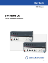
Application Diagrams
Application with “Show Me” Cables
12V
POWER IN
POWER OUT
RS-232
Tx
4
C G T +V
3
C G T +V
2
C G T +V
1
C G T +V
8
C G T +V
7
C G T +V
6
C G T +V
5
C G T +V
G
Tx Rx G
1.0A
MAX
1.0A
MAX
CONTACT IN / TALLY OUT COM
REMOTE
100-240V ~ 50/60 Hz
-- A MAX
1
2
CONFIGURABLE
HDMI
IN1606
HDMI
5
6
HDMI
A
B
3
4
INPUTS OUTPUTS AUDIO INPUTS OUTPUTS REMOTE
L 1
R
L 2
R
L 3
R
L 4
R
L 5
R
+48V
+48V
1 2
L R
VARIABLE
Tx Rx
RS-232
G
LAN
RESET
1
2
MIC/LINE
L 6
R
INPUT
LAN
POWER
12V
500mA
MAX
1 2 3 4
COM 3 IR
3
S G S G
Tx Rx
4
RELAY
3
4
COM1
Tx Rx
RTS CTS
COM 2 IR
1
S G S G
Tx Rx
2
RELAY
1
2
RS-232
RS-232
Ethernet
Ethernet
Flat Panel Display
HDMI Video and
Embedded Audio
Contact Closure and Tally
Contact Closure and Tally
Power
Supply
Extron
CTR 8
Eight Input Contact
Closure to RS-232
Control Module
Extron
IN1606
Scaling Presentation
Switcher
VGA/HDMI “Show Me” Cables
TCP/IP
Network
Extron
IPL 250
IP Link Control
Processor

CTR 8 • Panels and Cabling 5
Application with CCR 4BLB
--A MAX
POWER
12V
1
VIDEORGB/R-Y,Y,B-Y HDMI
DSC 301 HD
AUDIO
23
1
RS-232
Tx Rx G
23
INPUTS
OUTPUT
REMOTE
PWR
+ G
INPUTS
1 2 G 3 4 G
OUTPUTS
1 2 G 3 4 G
12V
POWER IN
POWER OUT
RS-232
Tx
4
CGT+V
3
CGT+V
2
CGT+V
1
CGT+V
8
CGT+V
7
CGT+V
6
CGT+V
5
CGT+V
G
Tx Rx G
1.0A
MAX
1.0A
MAX
CONTACT IN / TALLY OUT COM
REMOTE
CGT+V
PUSH PUSH
POWER GUIDEMENU RES 480 480p 720p 1080i 1080p
DIRECTV HD
SELECT
DIRECTV
Extron
DSC 301 HD
Three Input Compact
HDCP-Compliant Video Scaler
RS-232
Power Out
Tally
Contact Closure
Ground
Power Supply
12V 1A
Flat Panel Display
HDMI Video and
Embedded Audio
Extron
CTR 8
Eight Input Contact Closure
to RS-232 Control Module
Power Supply
DVD Player
Laptop
Extron
CCR 4BLB
Four-Button Contact Closure
Remote With Customizable
Backlit Buttons
Cable Box
Contact Closure AAP
Solder Cups
Normally
Closed (NC)
Normally
Open (NO)
Common
Ground (C)
LED (-)
LED (+)
PC
The diagram close-up below shows how to connect the CCR 4BLB to the CTR 8.
12V
POWER IN
POWER OUT
RS-232
Tx
4
CGT+V
3
CGT+V
2
CGT+V
1
CGT+V
8
CGT+V
7
CGT+V
6
CGT+V
5
CGT+V
G
Tx Rx G
1.0A
MAX
1.0A
MAX
CONTACT IN / TALLY OUT COM
REMOTE
PWR
+ G
INPUTS
1 2 G 3 4 G
OUTPUTS
1 2 G 3 4 G
CTR 8
CCR 4BLB
Tally
Contact Closure
Ground
Application with Individual Contact Closure Switch
12V
POWER IN
POWER OUT
RS-232
Tx
4
CGT+V
3
CGT+V
2
CGT+V
1
CGT+V
8
CGT+V
7
CGT+V
6
CGT+V
5
CGT+V
G
Tx Rx G
1.0A
MAX
1.0A
MAX
CONTACT IN / TALLY OUT COM
REMOTE
Two Contact Closure Switch AAP
PC
Solder Cups
Normally
Closed (NC)
Normally
Open (NO)
Common
Ground (C)
LED (-)
LED (+)
CTR 8
Resistor (R)
NOTE: Determine and select the appropriate
current-limiting resistor, if needed. Some b
utton
switches have the resistor built in.

CTR 8 • Remote Communication and Control 6
Remote
Communication
and Control
This section covers the following:
z Using Simple Instruction Set (SIS) Commands
z Symbols Used in this Guide
z Command and Response Table for SIS Commands
z A/V Muting
Using Simple Instruction Set (SIS) Commands
The CTR 8 is controlled remotely using Extron SIS commands issued from a host computer
running the Extron DataViewer utility or other control system. The host device is connected to the
3-pole captive screw connector on the rear panel.
The protocol is 9600 baud, 8 data bit, 1 stop bit, and no parity.
Host-to-CTR 8 Communications
SIS commands consist of strings (one or more characters per command field). No special
characters are required to begin or end a command sequence. When the CTR 8 determines that
a command is valid, it executes the command and sends a response to the host device.
Most responses from the CTR 8 end with a carriage return and a line feed (CR/LF = ]), which
signals the end of the response character string.
CTR 8-Initiated Messages
When a local event such as a change in signal status takes place, the CTR 8 sends a message
to the host, indicating the status change. No response is required from the host.
When the CTR 8 is first switched on, it sends the message:
(c) Copyright 20yy, Extron Electronics, CTR 8, V x.xx, 60‑1408‑01] where
20yy is the year the currently installed version of the firmware was released, and V x.xx is the
firmware version number.

CTR 8 • Remote Communication and Control 7
Symbols Used in this Guide
When programming in the field, certain characters are most conveniently represented by their
hexadecimal rather than their ASCII values. The table below shows the hexadecimal equivalent of
each ASCII character:
ASCII to HEX Conversion Ta ble
Space
.
Table 1. ASCII to HEX Conversion Table
] — carriage return with line feed
} — carriage return (no line feed)
• — space character
E — Escape key
The X/ values defined in this section are the variables used in the Command Response Table.
X) — Input 0-8
X@ — Input selection status
0 = Not Selected
1 = Selected
X# — A/V mute mode
0 = Normal operation, no muting (default)
1 = Channel 0 A/V mute (0!)
2 = Video Mute (1B) and Audio Mute (1Z)
3 = Video and Sync Mute (2B)
X$ — Mute LED mode
0 = Always on (default)
1 = Off when muted
2 = Blink when muted
X2% — Baud rate: 9600, 19200, 38400, 57600 (default = 9600)
NOTE: Unless otherwise indicated, commands are not case-sensitive.
Error Messages
E01 — Invalid output channel number (too large)
E10 — Invalid command
E13 — Invalid value (too large)

CTR 8 • Remote Communication and Control 8
Command and Response Table for SIS Commands
Command ASCII Command
(host to unit)
Response
(unit to host)
Additional
Description
Select input
X)! ChnX)] X) = input 0-8
View last selected input
!
X)]
Query contact closure status
S/s
X@X@X@X@X@X@X@X@]
Least significant input
on far left
Example response:
01000000]
Contact input 2 is
selected
Unidirectional Serial Data Port
Configure port parameters
Example command:
E2*X2%,n,8,1CP}
E2*19200,n,8,1CP }
Cpn02•CcpX2%,n,8,1]
n = Parity = None
8 = Data bits
1 = Stop bit
View parameters
E2CP} X2%,n,8,1]
A/V Mute Mode
Configure A/V mute mode
EX#*X$MUTM} MutmX#*X$]
View A/V mute mode setting
EMUTM} X#*X$]
Other
Information request
I/i
CTR•8]
Request part number
N/n
60‑xxxx‑xx]
View the part number
Query firmware version
Q/q
x.xx]
Firmware build (2
decimal places)
Query full firmware version
*Q/*q
x.xx.xxxx]
View the full firmware
Reset all device settings to
factory
EzXXX} Zpx]
A/V Muting
The CTR 8 allows A/V muting for a selected input. This feature allows users to press
the selected input button to mute and unmute the audio and video as needed during a
presentation.
• Press the button once to select an input (Select state)
• Press the same button again to activate A/V mute (De-select state)
• Press the button once more to return to the Select state, which selects the input and
unmutes the audio and video.
NOTE: The A/V mute feature is only triggered by contact closure. SIS input selection (for
example, entering 1! two times) will not trigger the de-select state.
A/V Mute Modes
There are three A/V mute modes, based on the device:
• Mute mode 1: Mutes switcher input by selecting channel 0
• Mute mode 2: Mutes video and audio individually
• Mute mode 3: Mutes video and sync
Mute mode 0 is the normal (default) single state operation. A/V mute is not activated in this
mode.
NOTE: See the next page for a partial list of Extron switchers that are compatible with
the different mute modes.

CTR 8 • Remote Communication and Control 9
A/V mute modes are activated via SIS commands sent to the CTR 8. The COM port then
sends SIS commands to the switcher. The table below shows the different commands that
the COM port sends for each A/V mute mode.
Button Input
Number
Button State Mute
mode 0
Mute
mode 1
Mute mode
2
Mute
mode 3
1 Select
1! 1! 1! 0B 0Z 1! 0B
1 De-select
‑ 0! 1B 1Z 2B
2 Select
2! 2! 2! 0B 0Z 2! 0B
2 De-select
‑ 0! 1B 1Z 2B
3 Select
3! 3! 3! 0B 0Z 3! 0B
3 De-select
‑ 0! 1B 1Z 2B
4 Select
4! 4! 4! 0B 0Z 4! 0B
4 De-select
‑ 0! 1B 1Z 2B
5 Select
5! 5! 5! 0B 0Z 5! 0B
5 De-select
‑ 0! 1B 1Z 2B
6 Select
6! 6! 6! 0B 0Z 6! 0B
6 De-select
‑ 0! 1B 1Z 2B
7 Select
7! 7! 7! 0B 0Z 7! 0B
7 De-select
‑ 0! 1B 1Z 2B
8 Select
8! 8! 8! 0B 0Z 8! 0B
8 De-select
‑ 0! 1B 1Z 2B
NOTES:
• A/V mute commands sent from the COM port
to the switcher:
0B = unmute video
1B = mute video (not sync)
2B = mute video and sync
0Z = unmute audio
1Z = mute audio
• A/V mute mode 0 does not have a De-select state.
The following is a partial list of Extron switchers for A/V mute modes 1, 2, and 3.
NOTE: Other switchers and scalers are compatible with the mute modes. Contact
Extron Technical Support for assistance with your Extron device.
• Mute mode 1: MLS 608, MPS 602
• Mute mode 2: MLS 608, DSC 301 HD, DVS 605
• Mute mode 3: IN1606, IN1608, DSC 301 HD, DVS 605
LED Responses for Video Muting
The CTR 8 allows button LED responses to indicate when video is muted. Button LEDs are
controlled by the Tally Output signal. The CTR 8 offers three different LED modes, which are
set by sending SIS commands to the Remote RS-232 port.
• LED Mode 0 = LED of selected input is always on (Default)
• LED Mode 1 = LED of selected input turns Off when muted
• LED Mode 2 = LED of selected input blinks when muted
NOTE: LED mode can be set only when A/V Mute Mode is 1, 2, or 3. If A/V Mute Mode
is 0, LED mode is 0.

CTR 8 • Updating Firmware 10
Updating
Firmware
Updates to the CTR 8 firmware are released periodically on the Extron website. You can find
which version is currently loaded on your CTR 8 using SIS commands. Compare this with the
latest release on the Extron website and decide whether to update your firmware.
TIP: Read the Release Notes provided on the website with the latest firmware to
determine whether you need the latest version.
This section covers the following:
z Downloading and Installing Firmware Loader
z Downloading CTR 8 Firmware
z Installing Firmware with Firmware Loader
Downloading and Installing Firmware Loader
Extron recommends using the Firmware Loader software to update the firmware on Extron
products. If you do not already have Firmware Loader installed on your computer, download it as
follows:
1. Go to the Extron website at www.extron.com and click the Download link.
2. Click the Software link on the left sidebar menu.
3. On the Download Center page, locate Firmware Loader and click its Download link.
Figure 7. Firmware Loader Download Link
4. On the next screen, enter the requested information, then click the Download
fw_loader_vnxnxn.exe button (where n is the Firmware Loader version number).
5. Follow the instructions on the rest of the download screens to save the executable Firmware
Loader installer file to your computer. Note the location to which the file was saved.
6. In Windows Explorer or another file browser, locate the downloaded executable installer file
and double-click to open it.
7. Follow the instructions on the Installation Wizard screens to install Firmware Loader on your
computer. Unless you specify otherwise, the installer program places the Firmware Loader
file, FWLoader.exe, at c:\Program Files\Extron\FWLoader.

CTR 8 • Updating Firmware 11
Downloading CTR 8 Firmware
Figure 8. Firmware Link on the Download Tab
To obtain the latest firmware version for the CTR 8:
1. Visit the Extron website (www.extron.com), click the Download link at the top of the
page.
2. Click the Firmware link on the left sidebar menu.
3. On the Download Center screen, locate the section for the CTR 8 firmware.
4. (Optional) click Release Notes. These notes show the issues that are addressed by the
latest update. If these issues do not affect you, you may decide not to upgrade the firmware.
5. Click the CTR 8 Download link.
6. On the next screen, enter the requested user information, then click Download.
7. Follow the instructions on the rest of the download screens to save the executable firmware
file to your computer. Note the location to which the file was saved.
8. In Windows Explorer or another file browser, locate the downloaded executable file, and
double-click to open it.
9. Follow the instructions on the Installation Wizard screens to install the new firmware on your
computer. A Release Notes file and a set of instructions for updating the firmware are also
loaded.
Installing Firmware with Firmware Loader
To load a new version of firmware to the CTR 8, connect your computer serial port to the Remote
port (see “c Remote RS-232 port” on page 4 for information on connecting to the serial port).
1. If you have not already done so, download and install the Firmware Loader executable
installer file to your computer (see Downloading and Installing Firmware Loader on
the previous page).
2. If necessary, download the latest version of CTR 8 firmware and install it on your computer
(see the previous section, Downloading CTR 8 Firmware).
3. Open Firmware Loader. The Firmware Loader dialog box opens with the Add Device
dialog in front of it.

CTR 8 • Updating Firmware 12
Figure 9. Opening Firmware Loader
4. In the Add Device dialog, select the device from the Device Names drop-down list.
5. From the Connection Method drop-down list, select RS-232.
6. RS-232: Select the appropriate options from the Com Port and Baud Rate menus (this
information is provided by your system administrator).
7. Click Connect. If the connection is successful, CTR 8 is displayed in green in the
Connected Device panel, followed by a green check mark.
8. Click Browse in the New Firmware File (Optional) panel.
9. In the Open dialog, navigate to the new firmware file, which has an S19 extension, and
double-click it.
Figure 10. Open Window for Firmware File Selection
ATTENTION: Valid firmware files must have the file extension S19. A file with any other
extension is not a firmware upgrade for this product and could cause the CTR 8 to
stop functioning.

CTR 8 • Updating Firmware 13
NOTES:
• The original factory-installed firmware is permanently available on the CTR 8.
If the attempted firmware upload fails for any reason, the unit reverts to the
factory version.
• By default, when the firmware is downloaded from the Extron site, it is saved in
one of the following paths:
C:\Program Files\Extron\Firmware\folder_name (Windows XP) or
C:\Program Files (x86)\Extron\Firmware\folder_name (Windows 7)
where folder_name may be CTR 8 or something similar.
In the Add Device dialog, the path to the new firmware file is displayed in the Path field.
Figure 11. Path to the New Firmware File on the Add Device Window
10. If this is the only device to which you are uploading firmware, click Add. The CTR 8
information is added to the Devices section of the Firmware Loader dialog box and the
Add Device dialog closes.
If you want to upload the firmware to multiple units that are connected to your
computer, do the following:
a. Click Add Next. Your first device is added to the Devices section of the Firmware
Loader dialog box, and the Add Device dialog remains open.
b. For each additional device you want to add, repeat steps 4 through 9, then click
Add Next.
c. For the last device, click Add (instead of Add Next) to add the device and to close the
Add Device dialog.

CTR 8 • Updating Firmware 14
Figure 12. Firmware Loader Screen with the CTR 8 Added
11. If you want to remove a device, do the following:
a. Click the names of the devices to be deleted, to highlight them.
b. Select Edit > Remove Selected Device(s) from the toolbar.
c. On the Remove Device(s) window, select or deselect any devices on the list as desired,
then click Remove.
To remove all devices, select Edit > Remove All Devices from the toolbar.
12. Click Begin. The following indicators show the progress of the update:
z The Transfer Time section shows the amounts of remaining and elapsed time for the
update.
z The Total Progress section displays a progress bar with Uploading... above it.
z In the Devices panel, the Progress column displays an incrementing percentage and
another progress bar. The Status column displays Uploading.
13. The upload is complete when the Remaining Time field shows 00.00.00, the Progress
column shows 100%, and Completed is displayed above the progress bar and in the Status
field. Close the Firmware Loader dialog.

CTR 8 • Mounting 15
Mounting
Tabletop Placement
Attach the four provided rubber feet to the bottom of the unit and place it in any convenient
location.
Rack Mounting
UL Guidelines for Rack Mounting
The following Underwriters Laboratories (UL) guidelines are relevant to the safe installation of
these products in a rack:
• Elevated operating ambient temperature — If the unit is installed in a closed or
multi-unit rack assembly, the operating ambient temperature of the rack environment
may be greater than room ambient temperature. Therefore, install the equipment in an
environment compatible with the maximum ambient temperature
(TMA = +122 °F, +50°C) specified by Extron.
• Reduced air flow — Install the equipment in the rack so that safe operation and
adequate air flow is provided to the unit.
• Mechanical loading — Mount the equipment in the rack so that a hazardous
condition is not achieved due to uneven mechanical loading.
• Circuit overloading — Connect the equipment to the supply circuit and consider the
effect that circuit overloading might have on overcurrent protection and supply wiring.
Consider the equipment nameplate ratings when addressing this concern.
• Reliable earthing (grounding) — Maintain reliable grounding of rack-mounted
equipment. Pay particular attention to supply connections other than direct
connections.
Rack Mounting Procedure
These units can be mounted an optional rack systems listed on the website (see
www.extron.com). To mount the unit on a rack shelf, follow the instructions provided with
the shelf accessories.
Back of the Rack Mounting Procedure
The CTR 8 can be mounted to the rear of a rack using an optional back of rack mounting kit
(see www.extron.com). The kit allows the product to be vertically mounted to the front or
rear rack supports and face either the front or the rear of the rack. To mount the unit, follow
the instructions provided with the kit.
Under-desk and Furniture Mounting
Mount the unit under a desk or podium, using the included under-desk mounting kit. Follow
the instructions provided with the kit.
/