Page is loading ...

READ THROUGH THIS MANUAL
BEFORE STARTING CONSTRUCTION.
IT CONTAINS IMPORTANT INSTRUCTIONS
AND WARNINGS CONCERNING THE
ASSEMBLY AND USE OF THIS MODEL.
WEIGHT
35–38 oz [992–1077g]
WING LOADING
7.5 – 8.0 oz/ft
2
[23–24 g/dm
2
]
RADIO
3-Channel, Two Standard Servos
or Two Mini Servos with
at least 35 g of torque.
Tower
Hobbies
®
guarantees
this kit to be
free from defects
in both material and
workmanship at the
date of purchase. This
warranty does not cover any
component parts damaged by
use or modification. In no case
shall Tower Hobbies’ liability exceed
the original cost of the purchased kit.
Further, Tower Hobbies reserves the right to
change or modify this warranty without notice.
In that Tower Hobbies has no control over the final
assembly or material used for final assembly, no
liability shall be assumed nor accepted for any damage
resulting from the use by the user of the final
user-assembled product. By the act of using the
user-assembled product, the user accepts all resulting liability.
If the buyer is not prepared to accept the liability associated with the
use of this product, the buyer is advised to return this kit immediately in
new and unused condition to the place of purchase.
To make a warranty claim send the defective part or item to Hobby Services at
the address below:
Hobby Services • 3002 N. Apollo Dr. Suite 1 • Champaign IL 61822 • USA
Include a letter stating your name, return shipping address, as much contact information
as possible (daytime telephone number, fax number, e-mail address), a detailed description
of the problem and a photocopy of the purchase receipt. Upon receipt of the package the
problem will be evaluated as quickly as possible.
WARRANTY
TOWA4020
© 2014 Tower Hobbies .
®
A subsidiary of Hobbico, Inc.
®
®
TOWER HOBBIES
Champaign, Illinois
(217) 398-8970 ext. 5
WINGSPAN
78.5 in [1995mm]
WING AREA
678 sq in [43.7 dm
2
]
LENGTH
41 in [1040 mm]
airsupport@hobbico.com
INSTRUCTION MANUAL
MOTOR
Included

2
TABLE OF CONTENTS
––––––––––––––––––
INTRODUCTION. . . . . . . . . . . . . . . . . . . . . . . . . . . . . . . . . 2
AMA . . . . . . . . . . . . . . . . . . . . . . . . . . . . . . . . . . . . . . . . . . . .2
SAFETY PRECAUTIONS . . . . . . . . . . . . . . . . . . . . . . . . . .2
ADDITIONAL ITEMS REQUIRED . . . . . . . . . . . . . . . . . .3
Radio Components. . . . . . . . . . . . . . . . . . . . . . . . . . . . . . 3
Battery and Charger . . . . . . . . . . . . . . . . . . . . . . . . . . . .3
Adhesives and Building Supplies. . . . . . . . . . . . . . . . . . .3
Hardware and Accessories . . . . . . . . . . . . . . . . . . . . . . . 3
KIT INSPECTION . . . . . . . . . . . . . . . . . . . . . . . . . . . . . . . . 3
ORDERING REPLACEMENT PARTS . . . . . . . . . . . . . . .3
CONTENTS . . . . . . . . . . . . . . . . . . . . . . . . . . . . . . . . . . . . . .4
ASSEMBLY . . . . . . . . . . . . . . . . . . . . . . . . . . . . . . . . . . . . . . 5
Preparations . . . . . . . . . . . . . . . . . . . . . . . . . . . . . . . . . . . 5
Join the Wings . . . . . . . . . . . . . . . . . . . . . . . . . . . . . . . . . 5
ASSEMBLE THE FUSELAGE . . . . . . . . . . . . . . . . . . . . . . . 6
Join the Stabilizer. . . . . . . . . . . . . . . . . . . . . . . . . . . . . . . 6
Join the Fin . . . . . . . . . . . . . . . . . . . . . . . . . . . . . . . . . . . . 7
Hook Up the Controls . . . . . . . . . . . . . . . . . . . . . . . . . . .8
Mount the Receiver. . . . . . . . . . . . . . . . . . . . . . . . . . . . . 10
GET THE MODEL READY TO FLY . . . . . . . . . . . . . . . . 10
Check the ESC . . . . . . . . . . . . . . . . . . . . . . . . . . . . . . . . 10
Check the Control Directions . . . . . . . . . . . . . . . . . . . . . 11
Set the Control Throws. . . . . . . . . . . . . . . . . . . . . . . . . . 11
Install the Propeller. . . . . . . . . . . . . . . . . . . . . . . . . . . . . 11
Apply the Decals . . . . . . . . . . . . . . . . . . . . . . . . . . . . . .12
Balance the Model (C.G.) . . . . . . . . . . . . . . . . . . . . . . . 12
PREFLIGHT . . . . . . . . . . . . . . . . . . . . . . . . . . . . . . . . . . . . . 13
Identify Your Model . . . . . . . . . . . . . . . . . . . . . . . . . . . . 13
Charge the Batteries. . . . . . . . . . . . . . . . . . . . . . . . . . . . 13
Range Check . . . . . . . . . . . . . . . . . . . . . . . . . . . . . . . . . 13
MOTOR SAFETY PRECAUTIONS . . . . . . . . . . . . . . . . 14
AMA SAFETY CODE (excerpts). . . . . . . . . . . . . . . . . . . . 14
General. . . . . . . . . . . . . . . . . . . . . . . . . . . . . . . . . . . . . . 14
Radio Control . . . . . . . . . . . . . . . . . . . . . . . . . . . . . . . . . 14
CHECK LIST . . . . . . . . . . . . . . . . . . . . . . . . . . . . . . . . . . . . 14
FIND A SAFE PLACE TO FLY. . . . . . . . . . . . . . . . . . . . . 15
FLYING . . . . . . . . . . . . . . . . . . . . . . . . . . . . . . . . . . . . . . . . 15
Mount the Wing . . . . . . . . . . . . . . . . . . . . . . . . . . . . . . . 15
Takeoff . . . . . . . . . . . . . . . . . . . . . . . . . . . . . . . . . . . . . . 15
Flight . . . . . . . . . . . . . . . . . . . . . . . . . . . . . . . . . . . . . . . . 16
Landing. . . . . . . . . . . . . . . . . . . . . . . . . . . . . . . . . . . . . . 16
INTRODUCTION
––––––––––––––––––––––––
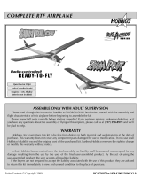
Thank you for purchasing the TOWER HOBBIES Vista
™
BL
EP ARF motor glider. Identical in construction to the Vista
ARF sailpane, this BL version features a 35mm brushless motor
that eliminates the need to lay out the Hi-Start launch system
typically required for thermal soaring. This BL version therefore
requires less space and time to get into the air! Easy-to-fl y
electric-powered motor gliders such as this are a great way for
beginners to get into the hobby–they are relatively inexpensive
and they fl y and react slowly enough to give novice fl yers time
to think and react. And when those rising air currents (thermals)
appear, the Vista BL EP ARF can still soar with the best of them.
AMA
––––––––––––––––––––––––––––––––––––
We urge you to join the AMA (Academy of Model Aeronautics)
and a local R/C club. The AMA is the governing body of model
aviation and membership is required to fl y at AMA clubs. Though
joining the AMA provides many benefi ts, one of the primary
reasons to join is liability protection. Coverage is not limited to
fl ying at contests or on the club fi eld. It even applies to fl ying at
public demonstrations and air shows. Failure to comply with the
Safety Code (excerpts printed in the back of the manual) may
endanger insurance coverage. Additionally, training programs
and instructors are available at AMA club sites to help you get
started the right way. There are over 2,500 AMA chartered clubs
across the country. Contact the AMA at the address or toll-free
phone number that follows.
Academy of Model Aeronautics
5151 East Memorial Drive
Muncie, IN 47302-9252
Tele. (800) 435-9262
Fax (765) 741-0057
Or via the Internet at: www.modelaircraft.org
IMPORTANT: Two of the most important things you can do to
preserve the radio controlled aircraft hobby are to avoid fl ying near
full-scale aircraft and avoid fl ying near or over groups of people.
SAFETY PRECAUTIONS
––––––––––––––––
PROTECT YOUR MODEL, YOURSELF & OTHERS…
FOLLOW THESE IMPORTANT SAFETY PRECAUTIONS
1. Your Vista BL EP ARF should not be considered a toy, but
rather a sophisticated, working model that functions very
much like a full-size airplane. Because of its performance
capabilities, the Vista BL ARF, if not assembled and
operated correctly, could possibly cause injury to yourself
or spectators and damage to property.
2. You must assemble the model according to the instructions.
Do not alter or modify the model, as doing so may result in
an unsafe or unfl yable model. In a few cases the instructions
may differ slightly from the photos. In those instances the
written instructions should be considered as correct.
3. You must take time to build straight, true and strong.
4. You must use an R/C radio system that is in fi rst-class
condition.
5. You must correctly install all R/C and other components so
that the model operates correctly on the ground and in the air.
6. You must check the operation of the model before every
fl ight to insure that all equipment is operating and that the
model has remained structurally sound. Be sure to check
clevises or other connectors often and replace them if they
show any signs of wear or fatigue.
7. If you are not an experienced pilot or have not fl own this type
of model before, we recommend that you get the assistance
of an experienced pilot in your R/C club for your fi rst fl ights.

3
If you’re not a member of a club, your local hobby shop has
information about clubs in your area whose membership
includes experienced pilots.
8. While this kit has been fl ight tested to exceed normal use,
if the plane will be used for extremely high-stress fl ying
the modeler is responsible for taking steps to reinforce the
high-stress points.
We, as the kit manufacturer, provide you with a top quality,
thoroughly tested kit and instructions, but ultimately the
quality and fl yability of your fi nished model depends on how
you build it; therefore, we cannot in any way guarantee the
performance of your completed model, and no representations
are expressed or implied as to the performance or safety of
your completed model.
REMEMBER: Take your time and follow the instructions to
end up with a well-built model.
ADDITIONAL ITEMS REQUIRED
–––––––
Radio Components
A minimum 3-channel radio (elevator, rudder and ESC control)
and two standard or mini servos with 35oz. of thrust are required
to fl y the Vista BL EP ARF. The Tactic TTX404 4-channel or
Futaba 4YF 4-channel radio system are great low cost radio
systems perfect for the Vista BL EP ARF.
■ TACJ2404 TTX404 4-channel radio system
■ TACM0235 (TSX35) standard servo
■ TACM0220 TSX20) mini servo
■ FUTK4200 4YF 4-channel radio system
■ FUTM0031 (S3003) standard servo
■ FUTM0415 (S3115) micro precision servo
■ TOWM4525 (TS-53) standard servo
Battery and Charger
■ A 3S 11.1V 1800mAh – 2200mAh LiPo battery is required
to power the Vista BL EP ARF
■ ElectriFly 1800mAh 30C (GPMP0855)
■ ElectriFly 2200mAh 30C (GPMP0861)
■ FlightPower 2200mAh 30C (FPWP3223)
■ FlightPower 2200mAh 50C (FPWP5223)
Most modelers may already have a suitable LiPo charger, but
for those that do not, the Duratrax Onyx 235 AC/DC Advanced
Peak Charger (DTXP4235) is one of the suitable chargers
recommended. The Onyx charger is perfect for 3S batteries
used with the Tower Vista BL EP ARF and may be powered
either by an external DC power source (such as a 12V battery),
or a 110V AC outlet. The Onyx also has an adjustable charge
rate to charge your batteries in as little as a half-hour or less
(depending on the condition of your batteries and manufacturer’s
specifi ed charge rate). The Onyx can also charge larger batteries
and batteries other than LiPo, so it is a versatile charger you can
grow into. The 235 also has and LCD digital display screen, so
you can see how much capacity it took to recharge the battery
(required for monitoring the condition of your batteries and
calculating how long you can fl y).
Adhesives and Building Supplies
■ Tower 30-minute epoxy (TOWR3810)
■ Mixing sticks (50, GPMR8055)
■ Mixing cups (GPMR8056)
■ Epoxy brushes (6, GPMR8060)
■ Denatured alcohol (for epoxy clean up)
■ Masking tape
■ Drill
■ Drill bits: 1/16" [1.6mm]
■ Stick-on segmented lead weights (GPMQ4485)
■ #1 Hobby knife (TOWR1010)
■ #11 blades (5-pack, TOWR1015)
■ Medium T-pins (HCAR5150)
■ CG Machine (GPMR2400)
■ Paper towels
Hardware and Accessories
■ Spare #64 rubber bands (TOWQ1220)
■ 21st Century Sealing Iron (COVR2700)
■ 21st Century Hot Sock (COVR2702
KIT INSPECTION
–––––––––––––––––––––––
Before assembly, take an inventory of this kit to make sure it is
complete, and inspect the parts to make sure they are of acceptable
quality. If any parts are missing or are not of acceptable quality, or
if you need assistance with assembly, contact Product Support.
When reporting defective or missing parts, use the part names
exactly as they are written in the Kit Contents list.
Hobbico Product Support Ph: (217) 398-8970 ext. 5
3002 N Apollo Drive Suite 1 Fax: (217) 398-7721
Champaign, IL 61822
E-mail: [email protected]
ORDERING REPLACEMENT PARTS
––––
Replacement parts for the Tower Hobbies Vista BL EP ARF are
available using the order numbers in the Replacement Parts
List that follows. The fastest, most economical service can be
provided by your hobby dealer or mail-order company.
To locate a hobby dealer, visit the Hobbico web site at www.
hobbico.com. Choose “Where to Buy” at the bottom of the menu
on the left side of the page. Follow the instructions provided on
the page to locate a U.S., Canadian or International dealer.
Parts may be ordered directly from Hobby Services by calling
(217) 398-0007, or via facsimile at (217) 398-7721, but full retail
prices and shipping and handling charges will apply. Illinois
and Nevada residents will also be charged sales tax. If ordering
via fax, include a Visa
®
or MasterCard
®
number and expiration
date for payment.

4
Mail parts orders Hobby Services
and payments by 3002 N Apollo Drive, Suite 1
personal check to: Champaign IL 61822
Be certain to specify the order number exactly as listed in the
Replacement Parts List. Payment by credit card or personal
check only; no C.O.D.
If additional assistance is required for any reason contact Product
Support by e-mail at [email protected], or by
telephone at (217) 398-8970.
Order No. Description
REPLACEMENT PARTS LIST
Fuselage
Wing
Tail Surfaces
Motor
Folding Prop Assembly
Folding Blade Set
Decals
ESC 30A
TOWA4021
TOWA4022
TOWA4023
TOWA4024
TOWA4025
TOWA4026
TOWA4027
TOWA4028
–––––––––––––––––––––––––––––––––––
CONTENTS
––––––––––––––––––––––––––––––––––––
1. Fuselage
2. Left Wing
3. Right Wing
4. Horizontal Stabilizer
5. Vertical Stabilizer
6. Fin Braces
7. Servo Rails
8. Wing Joiner
9. Wing Dowels
10. Prop and Spinner
11. Prop Adapter
12. #64 Rubber Bands
1
6
2
4
7
9
8
12
11
10
3
5

5
ASSEMBLY
–––––––––––––––––––––––––––––
Preparations
❏
1. Use a model airplane covering iron with a protective
covering sock to remove any wrinkles present in the covering.
The best temperature setting, with a covering sock on the iron,
is approximately 300° F. If this doesn’t seem to be enough
heat to shrink the wrinkles, increase iron temperature in small
increments until the wrinkles disappear.
Join the Wings
❏
1. Without using any glue, test fi t both wing halves together
with the wing joiner. Make sure the halves fi t together well
and there is no gap. If there is a problem with the fi t, look for
obstructions such as glue bumps or wood slivers inside the
wings where the joiners fi t. Make any adjustments necessary
to get a good fi t.
❏
2. Place a sheet of wax paper on your workbench and gather
all the items required for joining the wings: 30-minute epoxy,
a mixing cup, an epoxy mixing stick, an epoxy brush, paper
towels and denatured alcohol for epoxy clean up. Hint: To cut
down on waste, cut the paper towels into several small squares
as shown in the photo.
Caution: Do not use 5-minute epoxy for joining the wing
halves. It will not provide enough working time.
Read steps 3 and 4 all the way through before proceeding. It
is important to use the proper technique for joining the wing
halves to ensure a strong wing.
❏
3. Separate the wings and take out the joiner. Mix up
approximately 1/2 oz. [15cc] of 30-minute epoxy. Use an epoxy
brush to coat both ends of the wing and one half of the joiner
all the way around. Pour a generous amount of epoxy into one
of the wings where the joiner goes, and then slowly insert the
epoxy-coated half of the joiner. Wipe away excess epoxy as it
is forced out of the wing. Note: There must be no “empty space”
inside the wing where the joiner fi ts–the cavity must be fi lled
with epoxy. If no epoxy “oozes” out when you installed the joiner,
remove the joiner and add more epoxy. Then reinstall the joiner.
Proceed rapidly to the next step.

6
❏
4. Coat the protruding end of the joiner all the way around
with epoxy and pour epoxy into the other wing. Join the wing to
the other joiner/wing assembly, slowly pressing the two halves
together. Allow excess epoxy to drip out as you go. When the
wings come together, wipe away excess epoxy that is squeezed
out. Then use several strips of masking tape on both the top and
bottom of the wing to tightly hold the two halves together. If
epoxy continues to work out of the wing under the tape, remove
one strip at a time and wipe off the epoxy. Then replace the tape
with another strip. Do not disturb the wing until the epoxy has
hardened.
❏
5. After the epoxy has fully hardened, slowly and carefully
pull away the masking tape. If any of the covering loosened, iron
it back down with a covering iron on medium heat. Use a covering
sock over the iron to protect the Vista BL EP ARF’s fi nish.
ASSEMBLE THE FUSELAGE
––––––––––––
Join the Stabilizer
❏
1. Cut off any covering that has been wrapped around the
side of the fuselage over the top of the stab saddle where the
stabilizer goes.
❏
2. Place the stab on the fuselage, keying the notches in the
stab into the pegs on the fuselage. Use a fi ne-point, felt-tip pen
to mark the outline of the fuselage onto the stab.
❏
3. Take the stab off the fuselage and follow the Expert Tip
below or use a sharp hobby knife with a straightedge to cut along
the lines. If using a hobby knife to cut the covering, take great
care not to cut into the wood. Cutting into the wood will weaken
the structure which could cause it to fail in fl ight.
EXPERT TIP
How to cut covering from balsa.
Rather than using a hobby knife which could inadvertently
cut into the balsa, use a heated soldering iron. Move the iron
at a pace that will just melt the covering without burning into
the wood–the hotter the soldering iron, the faster you will
have to move it. A sharp tip isn’t necessary, but a fi ne-point
does work best.
❏
4. Peel the covering from the bottom of the stabilizer.

7
❏
5. Reposition the stabilizer onto the fuselage. Resting the
fuselage on your workbench, place a weight on top of the stab
to hold it down. View the fuselage from the rear. If the stab is
parallel with the workbench, proceed to the next step. If the
stab is not parallel with the workbench, remove the stab and
use medium-grit sandpaper to sand down the “high side” of the
stab saddle where the stab rests until you can get the stab level.
❏
6. Use 30-minute epoxy to glue the stab into position–be
certain to coat both the bottom of the stab and the fuselage with
epoxy. Use weight or T-pins to hold the stab in position until
the epoxy hardens.
Join the Fin
❏
1. Place the fi n on the fuselage, “keying” the dowels in the
bottom into the holes in the fuselage and the stab. Without
using any glue, place the tri-stock fi n braces on both sides of
the fi n. The same as was done with the bottom of the stab, use
a fi ne-point, felt-tip pen to mark the outline of the fi n braces
onto the fuselage top and the fi n so you will know where to cut
off the covering.
❏
2. Working carefully without cutting into the balsa, use your
heated soldering iron or a sharp hobby knife to cut the covering
from the sides of the fi n and the top of the fuselage. Make sure
you cut just inside the lines–approximately 1/32" [.5mm]–so that
none of the balsa will be exposed when all the parts are joined.
❏
3. Use one of your paper towel squares moistened with
denatured alcohol to wipe away the ink lines.
❏
4. Use 30-minute epoxy to glue the fi n to the fuselage with
T-pins to hold the fi n in position. Before the epoxy hardens use
a builder’s square to check to see if the fi n is perpendicular to
the stab. If necessary, use tape to pull the fi n over to one side
or the other to get the fi n vertical. Allow the epoxy to harden
before proceeding.

8
❏
5. Take out the T-pins. Glue the tri-stock fi n braces into
position with 30-minute epoxy, using T-pins to hold them in place.
❏
6. While you have some epoxy mixed, glue in both wing
dowels.
❏
7. Fit both hardwood servo rails in the slots in both sides of
the fuselage. Position the forward rail as far forward as it will
go and glue it into place, but do not glue in the aft rail until
instructed to do so.
Hook Up the Controls
❏
1. Connect the clevis to the third hole out from the bottom
of the elevator horn.
Note: If the silicone retainer on the elevator clevis rubs against
the inside of the fuselage sides, use a hobby knife to trim the
inside of the fuselage as necessary for free, smooth movement.
❏
2. Connect the rudder pushrod to the control horn the
same way.

9
Refer to this photo for the following four steps.
❏
3. Position the servos on the rails and slide them forward
against the forward rail. Note the position of the splined output
shaft on the servos (the elevator servo is facing aft and the
rudder servo is facing forward). Space the rail approximately
3/32" [3mm] aft of the servos, and then securely glue the rail
into position.
❏
4. Place the servo arms on the servos–if your servos came
with a selection of servo arms, use ones that will not interfere
with the other servo or the fuselage sides. For Futaba
®
and Tactic
servos, use the six-arm servo arms and cut off the unused arms.
❏
5. Position the left servo all the way over to the left side of
the fuselage. Drill 1/16" [1.6 mm] holes through the rails for the
servo mounting screws. Mount the servo with the screws that
came with it.
❏
6. Move the rudder servo all the way over to the elevator
servo. Drill 1/16" [1.6mm] holes through the rails and mount
the rudder servo with the screws that came with it.
❏
7. Center the servo arms as shown, holding the elevator
pushrod so the elevator is centered. Mark the pushrod where it
crosses the holes in the elevator servo arm.
❏
8. Use pliers to make a 90° bend in the pushrod at the mark
you made.
Pushrod Wire
Servo Horn
1/16”
❏
9. Take the servo arm off the servo. Enlarge the holes in the
servo arms with a servo horn drill (HCAR0698), a 5/64" [2mm]
drill bit or a hobby knife. Connect the pushrod to the outer hole
in the elevator servo using a 90° pushrod connector. Cut the
pushrod 1/16" [1.6mm] from the connector. Then replace the
servo arm on the servo.
❏
10. Connect the rudder pushrod to the rudder servo the
same way.

10
Mount the Receiver
❏
1. Cut a 1" [25mm] long piece of adhesive backed hook and
loop material. Apply one of the pieces to the receiver tray and
the opposite piece to the bottom of the receiver. Secure the
receiver on the receiver tray. Connect the servos and ESC to the
receiver. If you are fl ying with a 72 MHz receiver, use hemostats
or small needle-nose pliers to guide the antenna down and out
the antenna tube next to the elevator pushrod tube.
❏
2. Remove the battery hatch cover by grabbing it at the back
end and pulling it back until the tab at the front clears the fuselage.
❏
3. Apply the remaining piece of adhesive backed hook and
loop material to the top of the battery tray. Apply the opposite
piece of the adhesive back hook and loop material to the back
of your LiPo battery.
❏
4. Insert the battery into the battery compartment from the
front. Do not connect the motor battery to the ESC until instructed
to do so when setting up the radio system later.
GET THE MODEL READY TO FLY
––––––
Check the ESC
ATTENTION!!! Great care must always be used when
working on electric-powered models. Unlike glow engines,
electric motors can turn on unexpectedly if you aren’t paying
attention and inadvertently activate the throttle. Follow these
instructions to operate the motor correctly and be certain it
is properly set up.
❏
1. Until the radio system has been properly set up and you
are familiar with the operation of your motor and ESC, the
propeller should not be installed on the model to prevent injury
if the motor is inadvertently powered up and the propeller turns.
The following steps will require charged batteries. If you
haven’t yet done so, charge the motor battery and the batteries
in your transmitter.
❏
2. If using Futaba and Tactic transmitters, set the reversing
function for the throttle control in your transmitter to reverse.
❏
3. Center the trims on the transmitter and lower the throttle
stick all the way.
❏
4. Swing the radio hatch cover to the side.
❏
5. Take the servo arms off of the servos. With the propeller
off the motor, switch on the transmitter and connect the battery
to the ESC (the battery does not have to be inside the model–you
may just set it to the side).
❏
6. At this time the ESC is in “safe” mode and will not allow
the motor to turn until the system is “armed.” To arm the ESC
advance the throttle stick all the way forward and hold it there
until the motor beeps twice. Lower the throttle stick until the
motor beeps twice. Now the ESC is armed and the motor will
turn the next time the throttle is advanced.
❏
7. Slowly advance the throttle and the motor will turn
counterclockwise. Move the throttle stick to different positions
and see that the motor will react accordingly. When the throttle
stick is returned to the “off” position the motor will abruptly
stop. This is the “brake” function which allows the propeller to
fold backward, thus reducing drag when the Vista BL EP ARF
is gliding.
NOTE: If the brake does not function, unplug the motor battery,
and move the throttle stick to full throttle. Reconnect the motor
battery. The motor will beep twice. Move the throttle stick to
off. The motor will beep twice. Move the throttle to full again
until the motor beeps twice and then lower the throttle stick to
off. The motor is now armed.
❏
8. The system will be turned off when the motor battery
is unplugged. When it’s time for the next fl ight the “arming”
procedure must be repeated. When you get to the fl ying fi eld do
not arm the motor until you are actually ready to launch the model.

11
ATTENTION!!! The motor battery should never be plugged
in without the transmitter switch being on. Otherwise, the
receiver could pick up errant signals, inadvertently causing
the servos to move or the motor to activate. Always turn on
the transmitter fi rst and unplug the motor battery fi rst.
Check the Control Directions
❏
1. With the transmitter and receiver on and the trims centered,
make sure the elevator and rudder servo arms are centered, or
perpendicular to the servos. If necessary, remove the arms from
the servos and reinstall them so they will be perpendicular to
the servos. Install the screws that hold on the servo arms.
❏
2. With the transmitter and receiver still on, observe the
rudder and elevator to see if they are still centered. If necessary,
remove the clevises from the control horns and adjust the length
of the pushrods and reconnect the clevises to the horns so the
rudder and elevator are centered.
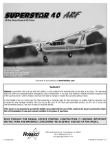
FULL
THROTTLE
ELEVATOR
MOVES DOWN
3-CHANNEL
RADIO SET UP
(STANDARD MODE 2)
RUDDER
MOVES
RIGHT
❏
3. Make certain the elevator, rudder and motor respond in
the correct direction as shown in the diagram. If necessary, use
the servo reversing function in your transmitter to reverse the
direction of the elevator and rudder.
Set the Control Throws
Use a ruler to measure and set the control throw of the elevator
and rudder as indicated in the chart that follows. If your radio
does not have dual rates, we recommend setting the throws at
the low rate setting.
Note: The rudder throw is measured at the bottom of the rudder.
THESE ARE THE RECOMMENDED CONTROL SURFACE THROWS:
ELEVATORRUDDER
5/8"
[16 mm]
UP DOWN
1-1/2"
[38 mm]
RIGHT LEFT
3/8"
[9.5 mm]
UP DOWN
1"
[25 mm]
RIGHT LEFT
5/8"
[16 mm]
1-1/2"
[38 mm]
3/8"
[9.5 mm]
1"
[25 mm]
HIGH RATE
LOW RATE
IMPORTANT: The Vista BL EP ARF has been extensively
fl own and tested to arrive at the throws at which it fl ies best.
Flying your model at these throws will provide you with the
greatest chance for successful fi rst fl ights. If, after you have
become accustomed to the way the Vista BL EP ARF fl ies,
you would like to change the throws to suit your taste that is
fi ne. However, too much control throw could make the model
diffi cult to control, so remember, “more is not always better.”
Install the Propeller
❏
1. Slide the aluminum collet type prop adapter onto the
motor shaft.

12
❏
2. Install the propeller and propeller backplate on the prop
adapter. Make sure the hex on the prop adapter keys into the
hex on the back of the backplate. Secure the prop to the adapter
with the plastic washer and aluminum hex nut, making sure to
leave a 1/16" [1.5mm] gap between the backplate and front of
the fuselage.
❏
3. Install and secure the spinner cone to the prop adapter
with the included screw.
Apply the Decals
❏
1. The decals are die-cut from the factory.
❏
2. Be certain the model is clean and free from oily fi ngerprints
and dust. Prepare a dishpan or small bucket with a mixture of
liquid dish soap and warm water—about 1/2 teaspoon of soap per
gallon of water. Submerse one of the decals in the solution and
peel off the paper backing. Note: Even though the decals have
a “sticky-back” and are not the water transfer type, submersing
them in soap & water allows accurate positioning and reduces
air bubbles underneath.
❏
3. Position decal on the model where desired. Holding the
decal down, use a paper towel to wipe most of the water away.
❏
4. Use a piece of soft balsa or something similar to squeegee
remaining water from under the decal. Apply the rest of the
decals the same way.
Balance the Model (C.G.)
More than any other factor, the C.G. (balance point) can have
the greatest effect on how a model fl ies, and may determine
whether or not your fi rst fl ight will be successful. If you
value this model and wish to enjoy it for many fl ights, DO
NOT OVERLOOK THIS IMPORTANT PROCEDURE.
A model that is not properly balanced will be unstable and
possibly unfl yable.
At this stage the model should be in ready-to-fl y condition with
all of the systems in place including the servos, battery (not
plugged in), propeller assembly and receiver.

13
❏
1. If you will be using a Great Planes C.G. Machine to balance
your model, set the rulers to 3-1/8" [80mm]. Place the plane on
the Machine. If you will not be using the C.G. Machine, use a
felt-tip pen or 1/8" [3mm]-wide tape to mark a line noting the
C.G. on the bottom of the wing 3-1/8" [80mm] back from the
leading edge.
This is where your model should balance for the fi rst fl ights.
Later, you may wish to experiment by shifting the C.G. up
to 3/8" [9.5mm] forward or 3/8" [9.5mm] back to change the
fl ying characteristics. Moving the C.G. forward may improve
wind penetration and stability, but the model will then fl y
and land a little faster. Moving the C.G. aft makes the model
lighter and more responsive to thermals, but could also cause
it to become too diffi cult to control. In any case, start at the
recommended balance point and do not at any time balance
the model outside the specifi ed range.
❏
2. Attach the wing to the fuselage with a couple of rubber
bands. The model must be totally ready to fl y with all of the
components installed. Place the model on the Great Planes CG
Machine or lift it at the balance point you marked. You should
be able to feel the tape lines with your fi ngers.
❏
3. With the plane on the CG Machine or when lifting it
with your fi ngers at the balance point, if the nose drops the
model is nose-heavy and weight must be added to the tail to
get it to balance. If the tail drops the model is tail-heavy and
weight must be added in the nose to get it to balance. Without
actually sticking it on, rest the correct amount of Great Planes
Self-Adhesive Lead Weight on the nose or tail of the model to
fi nd out how much is required.
❏
4. After determining the amount of weight required, remove
the model from the CG Machine and adhere the weight where
needed–to the side of the fuselage under the tail or inside the
fuselage behind the motor.
❏
5. IMPORTANT: If you found it necessary to add any weight,
recheck the C.G. after the weight has been installed.
PREFLIGHT
–––––––––––––––––––––––––––––
Identify Your Model
No matter if you fl y at an AMA sanctioned R/C club site or if
you fl y somewhere on your own, you should always have your
name, address, telephone number and AMA number on or inside
your model. It is required at all AMA R/C club fl ying sites and
AMA sanctioned fl ying events. Fill out the identifi cation tag on
the back cover page and place it on or inside your model.
Charge the Batteries
Follow the battery charging instructions that came with your
radio control system to charge the batteries. You should always
charge your transmitter and receiver batteries the night before
you go fl ying, and at other times as recommended by the radio
manufacturer.
CAUTION: Unless the instructions that came with your radio
system state differently, the initial charge on new transmitter
and receiver batteries should be done for 15 hours using the
slow-charger that came with the radio system. This will
“condition” the batteries so that the next charge may be done
using the fast-charger of your choice. If the initial charge is
done with a fast-charger, the batteries may not reach their
full capacity and you may be fl ying with batteries that are
only partially charged.
Range Check
Check the operational range of your radio on the ground before
the fi rst fl ight of each day. With the transmitter antenna collapsed
and the receiver and transmitter on, you should able to walk at
least 100 feet away from the model and still have control. Perform
this same check with the motor running at various speeds as
well. Have an assistant stand by your model and, while you
work the controls, tell you what the control surfaces are doing.
If the control surfaces do not respond correctly, do not fl y! Find
and correct the problem fi rst. Look for loose servo connections,
broken wires, or corroded wires on old servo connectors.

14
MOTOR SAFETY PRECAUTIONS
––––––––
Failure to follow these safety precautions may
result in severe injury to yourself and others.
■ Get help from an experienced pilot when learning to
operate motors.
■ Use safety glasses when running motors.
■ Do not run the motor in an area of loose gravel or sand;
the propeller may throw such material in your face or eyes.
■ Keep your face and body as well as all spectators away
from the plane of rotation of the propeller as you start
and run the motor.
■ Keep these items away from the prop: loose clothing, shirt
sleeves, ties, scarves, long hair or loose objects such as
pencils or screwdrivers that may fall out of shirt or jacket
pockets into the prop.
■ The motor could get hot! Do not touch it during or right
after operation.
■ When working on your plane, remove the propeller if the
motor battery will be connected.
■ Always remove the motor battery from the plane when
charging.
■ Follow the charging instructions included with your
charger for charging LiPo batteries. LiPo batteries can
cause serious damage if misused.
■ Never leave the LiPo battery unattended while charging.
If the LiPo battery becomes hot or starts to swell, stop
charging and remove the battery to a safe location.
AMA SAFETY CODE (excerpts)
––––––––
Read and abide by the following excerpts from the Academy of
Model Aeronautics Safety Code. For the complete Safety Code
refer to Model Aviation magazine, the AMA web site or the
Code that came with your AMA license.
General
1) I will not fl y my model aircraft in sanctioned events, air shows,
or model fl ying demonstrations until it has been proven to be
airworthy by having been previously, successfully fl ight tested.
2) I will not fl y my model aircraft higher than approximately
400 feet within 3 miles of an airport without notifying the
airport operator. I will give right-of-way and avoid fl ying in the
proximity of full-scale aircraft. Where necessary, an observer
shall be utilized to supervise fl ying to avoid having models fl y
in the proximity of full-scale aircraft.
3) Where established, I will abide by the safety rules for the
fl ying site I use, and I will not willfully and deliberately fl y my
models in a careless, reckless and/or dangerous manner.
5) I will not fl y my model unless it is identifi ed with my name
and address or AMA number, on or in the model. Note: This
does not apply to models while being fl own indoors.
7) I will not operate models with pyrotechnics (any device that
explodes, burns, or propels a projectile of any kind).
Radio Control
1) I will have completed a successful radio equipment ground
check before the fi rst fl ight of a new or repaired model.
2) I will not fl y my model aircraft in the presence of spectators
until I become a qualifi ed fl ier, unless assisted by an experienced
helper.
3) At all fl ying sites a straight or curved line(s) must be established
in front of which all fl ying takes place with the other side for
spectators. Only personnel involved with fl ying the aircraft are
allowed at or in the front of the fl ight line. Intentional fl ying
behind the fl ight line is prohibited.
4) I will operate my model using only radio control frequencies
currently allowed by the Federal Communications Commission.
5) I will not knowingly operate my model within three miles
of any pre-existing fl ying site except in accordance with the
frequency sharing agreement listed [in the complete AMA
Safety Code].
9) Under no circumstances may a pilot or other person touch a
powered model in fl ight; nor should any part of the model, other
than the landing gear, intentionally touch the ground except
while landing.
CHECK LIST
–––––––––––––––––––––––––––––
Use this Check List to make sure you haven’t
forgotten anything during the last few seconds
of preparation.
❏
1. Check the C.G. according to the measurements provided
in the manual.
❏
2. Be certain the receiver is securely mounted.
❏
3. Confi rm that all controls operate in the correct direction
and the throws are set up according to the manual.
❏
4. Make sure all the servo arms are mounted to the servos
with the screws included with your radio.
❏
5. Place your name, address, AMA number and telephone
number on or inside your model. There is an identifi cation tag
on the back cover page.
❏
6. If you wish to photograph your model, do so before your
fi rst fl ight.
❏
7. Range check your radio when you get to the fl ying fi eld.

15
FIND A SAFE PLACE TO FLY
–––––––––––
The best place to fl y any model is at an AMA chartered club
fi eld. Club fi elds are set up for R/C fl ying, making your outing
safer and more enjoyable. We recommend that you join the AMA
and a local club so you can have a safe place to fl y and have
insurance to cover you in case of a fl ying accident. The AMA
address and telephone number are in the front of this manual.
If there is no club or R/C fl ying fi eld in your area, fi nd a suitable
site that is clear of trees, telephone poles, buildings, towers, busy
streets and other obstacles. Since you are not fl ying at a sanctioned
AMA site, be aware that there may be others like yourself who
could be fl ying nearby. When fl ying on 72 MHz, if both of your
models happen to be on the same frequency, interference will
likely cause one or both of the models to crash. An acceptable
minimum distance between fl ying models is fi ve miles, so keep
this in mind when searching for a fl ying site.
In addition to obstacles, it is important to be aware of people who
may wander into the area once you begin fl ying. At AMA club
fl ying sites it is a severe rule infraction to fl y over others and this
is a good practice if fl ying elsewhere. R/C models tend to attract
onlookers who may pose two main problems; fi rst is the danger
of actually crashing your model into a person, causing injury.
Second is the distraction by those who ask you questions while
you are trying to concentrate on fl ying. To minimize or avoid this
problem, have an assistant standing by who can spot people who
wander into your fl ying site (so you can avoid fl ying over them)
and who can perform “crowd control” if people start to gather.
FLYING
––––––––––––––––––––––––––––––––––
Mount the Wing
Mount the wing to the fuselage with the ten (10) #64 rubber
bands that came with the model. Install them one at a time,
crisscrossing the last two. Never use torn, cracked or oily
rubber bands.
If the rubber bands you will be using are different from those
recommended, consult an experienced modeler to make certain
they are strong enough, and that you have used enough of them.
If uncertain, force the front of the wing off of the wing saddle.
There should be considerable resistance! If the wing can be
forced from the fuselage without having to strain your hands,
then there are probably not enough rubber bands.
IMPORTANT!!! Flying a model with too few rubber bands
can be dangerous. The wing could actually detach from
the fuselage resulting in a crash. If the model exhibits any
tendencies that indicate there are not enough rubber bands,
immediately land and closely inspect the model for damage.
If no damage is found, add more rubber bands.
Takeoff
IMPORTANT: If you are an inexperienced modeler we strongly
urge you to seek the assistance of a competent, experienced R/C
pilot to check your model for airworthiness AND to teach you
how to fl y. No matter how stable or “forgiving” the Vista BL ARF
is, attempting to learn to fl y on your own is dangerous and may
result in destruction of your model or even injury to yourself
and others. Therefore, fi nd an instructor and fl y only under his or
her guidance and supervision until you have acquired the skills
necessary for safe and fully controlled operation of your model.
WIND
Pilot
Launch
Assistant
The Vista BL EP ARF may be self-launched by the pilot, but if
you are a beginner it will be easier to have an assistant launch
the Vista BL EP ARF for you. Switch on the transmitter, throttle
stick in bottom position, then plug the motor battery into the
ESC. Hold the fuselage under the wing. Before fl ying any model,
always check to be certain that all the controls are operating
and in the correct direction by moving the control sticks on
the transmitter and observing their response. Once you have
confi rmed that the controls are operating correctly, point the
nose into the wind and apply full power. Toss the model into
the air at a nose-level or slightly nose-up attitude. The model
should climb gently, but be ready on the controls to keep the
wings level and model on a straight-out, slightly nose-up ascent.
Reduce the throttle to half. Once at a comfortable altitude, use
rudder and elevator trim as necessary to get the Vista BL EP
ARF to fl y straight-and-level when the control sticks are neutral.
When the model has reached enough altitude (50 to 100 feet [15
to 30m]) make the fi rst turn away from yourself and the takeoff
area. Continue to control the model, keeping it on the intended
fl ight path while climbing at a comfortable rate.

16
WIND
Pilot
“Race Track
Pattern”
Downwind Leg
Upwind Leg
Flight
Continue to fl y the model in the “race track” pattern, making
the downwind turn toward you and the upwind turn away from
you. If you are experienced enough and can control the model in
different orientations, execute fi gure eights turning the model
toward you in the middle of the “racetrack.” Throttle back or
cut power altogether when you get to an altitude where the Vista
BL EP ARF will be able to glide for a while. Add power when
necessary to regain altitude. Once you become an experienced
pilot, you will learn how to search for rising air currents where
motor power will no longer be necessary to remain aloft for ten,
twenty, thirty minutes or more. Total run time under full-power
should be approximately four to fi ve minutes, so even without
the assistance of rising air currents, the Vista BL EP ARF should
be able to remain aloft for at least six minutes.
Mind your battery power level, but use this fi rst fl ight to become
familiar with your model before landing. With most electric
planes it is best to have a timer set on your transmitter or a
separate timer with an alarm to alert you when the battery may
be getting low. This will require a few fl ights before determining
the maximum fl ight time you can achieve with the batteries.
This will prevent the downwind auto motor cutoff over the end
of the fl ying fi eld.
Landing
Align the plane with the landing zone and always land into
the wind. Increase or decrease motor power as necessary to
maintain your descent. When the model is a foot or two [.5m]
from the ground, increasingly apply “up” elevator to slow the
model without allowing it to climb. “Skim” the ground until
fl ying speed is lost and the model fi nally touches down as gently
as possible. It will probably skid for several feet, so a grassy
landing area is preferred.
Congratulations! You’ve just made your fi rst fl ight. Remove
the battery and, if the motor has been running for a while and
is still warm, allow it to cool before installing a charged battery
and making another fl ight.
One fi nal note about fl ying your Vista BL EP ARF. Have a goal
or a fl ight plan in mind for each fl ight. Rather than taking to the
air without knowing what you are going to do, take a minute
to think about the next fl ight–whether it’s searching for rising
air currents (thermals) or learning how to control the model in
different orientations. A little planning ahead should keep you
from executing an impulsive maneuver you weren’t actually
ready for possibly resulting in a crash.
Have a ball! But always stay in control and fl y
in a safe manner.
GOOD LUCK AND GREAT FLYING!
Cut out or copy the identifi cation tag and put it on or inside
your model.
This model belongs to:
Name
Address
City, State, Zip
Phone Number
AMA Number
/