Page is loading ...

WCGD FULL SIZE GAS
CONVECTION OVEN
WCGD
- NOTICE -
This Manual is prepared for the use of trained Hobart Service Technicians and should not
be used by those not properly qualified.
This manual is not intended to be all encompassing. If you have not attended a Hobart Service
School for this product, you should read, in its entirety, the repair procedure you wish to
perform to determine if you have the necessary tools, instruments and skills required to
perform the procedure. Procedures for which you do not have the necessary tools,
instruments and skills should be performed by a trained Hobart Service Technician.
The reproduction, transfer, sale or other use of this manual, without the express written
consent of Hobart, is prohibited.
This manual has been provided to you by ITW Food Equipment Group LLC ("ITW FEG")
without charge and remains the property of ITW FEG, and by accepting this manual you agree
that you will return it to ITW FEG promptly upon its request for such return at any time in the
future.
SERVICE MANUAL
F45990 (1223)
WOLF IS A DIVISION OF ITW FOOD EQUIPMENT GROUP, LLC 3600 NORTH POINT BLVD., BALTIMORE, MD 21222

TABLE OF CONTENTS
1. GENERAL ............................................................................................... 4
INTRODUCTION ....................................................................................... 4
INSTALLATION, OPERATION AND CLEANING ......................................................... 4
TOOLS ................................................................................................. 4
SPECIFICATIONS ...................................................................................... 4
LUBRICATION ......................................................................................... 4
2. REMOVAL AND REPLACEMENT OF PARTS ............................................................. 5
COVERS AND PANELS ................................................................................ 5
TOP FRONT COVER ............................................................................... 5
BOTTOM FRONT COVER .......................................................................... 5
CONTROL PANEL ................................................................................. 5
RIGHT SIDE PANEL ................................................................................ 5
CONTROL PANEL COMPONENTS ..................................................................... 6
COMPONENT PANEL COMPONENTS ................................................................. 6
TEMPERATURE PROBE ............................................................................... 7
GAS BURNER ......................................................................................... 7
GAS ORIFICE .......................................................................................... 8
GAS SOLENOID VALVE ................................................................................ 9
IGNITION CONTROL MODULE ....................................................................... 10
SPARK IGNITER AND FLAME SENSE ................................................................ 10
BLOWER AND MOTOR ............................................................................... 11
OVEN DOORS (SIMULTANEOUS DOORS) ........................................................... 12
DOOR WINDOW ...................................................................................... 13
DOOR SWITCH ....................................................................................... 14
HIGH LIMIT THERMOSTAT ........................................................................... 15
INTERIOR LIGHTS (SIDE MOUNTED, SQUARE) ...................................................... 15
COOLING FAN ........................................................................................ 17
3. SERVICE PROCEDURES AND ADJUSTMENTS ........................................................ 18
SOLID STATE TEMPERATURE CONTROL CALIBRATION ............................................ 18
SOLID STATE TEMPERATURE CONTROL TEST ..................................................... 19
TEMPERATURE PROBE TEST ....................................................................... 20
GAS VALVE PRESSURE CHECK ..................................................................... 20
VERIFICATION OF SPARK AT IGNITOR .............................................................. 22
DOOR SWITCH ADJUSTMENT ....................................................................... 22
BLOWER ADJUSTMENT .............................................................................. 23
DOOR ADJUSTMENT ................................................................................. 23
DOOR CHAIN ADJUSTMENT (SIMULTANEOUS DOORS) ............................................. 24
INTRODUCTION .................................................................................. 24
PROCEDURE ..................................................................................... 24
FLAME SENSE CURRENT TEST ...................................................................... 25
4. FIRMWARE / SOFTWARE .............................................................................. 28
FIRMWARE / SOFTWARE ............................................................................ 28
5. PROGRAMMING ....................................................................................... 29
PROGRAMMING ...................................................................................... 29
6. ELECTRIC OPERATION ................................................................................ 30
COMPONENT LAYOUT AND FUNCTION .............................................................. 30
7. SEQUENCE OF OPERATION ........................................................................... 33
SEQUENCE OF OPERATION ......................................................................... 33
WKGD WITH ROAST & HOLD OPTION (SOLID STATE TEMPERATURE CONTROL) .............. 33
8. DIAGRAMS ............................................................................................. 36
WCGD FULL SIZE GAS CONVECTION OVEN
F45990 (1223) Page 2 of 41

SCHEMATIC .......................................................................................... 37
DIAGRAM ............................................................................................. 38
9. TROUBLESHOOTING .................................................................................. 39
ALL MODELS ......................................................................................... 39
IGNITION MODULE DIAGNOSTICS ................................................................... 40
WCGD FULL SIZE GAS CONVECTION OVEN
Page 3 of 41 F45990 (1223)

1. GENERAL
INTRODUCTION
Procedures in this manual will apply to all models unless specified. Pictures and illustrations can be of any model
unless the picture or illustration needs to be model specific.
FEATURES
MODEL CAVITY DEPTH TEMPERATURE
CONTROL DOORS (50/50) COOK TIMER
WCGD 26.5" Solid State Simultaneus 1-Hour Dial
INSTALLATION, OPERATION AND
CLEANING
Refer to the Instruction Manual for detailed installation
instructions on single or stacked ovens.
TOOLS
Standard
• Standard set of hand tools.
•Metric set of hand tools.
• VOM with measuring micro amp current tester.
Any VOM with minimum of CAT III 600V, UL/
CSA/TUV/ETL certified. Sensitivity of at least
20,000 ohms per volt can be used. Ability to
measure uF microfarids. In addition, meter leads
must also be a minimum of CAT III 600V.
• Clamp-on type amp meter with minimum of
NFPA-70E CAT III 600V, UL/CSA/TUV/ETL
certified.
• Temperature tester (thermocouple type).
• Field service grounding kit.
Special
• Manometer.
• Gear Puller to remove blower.
SPECIFICATIONS
Electrical
Voltage - 120/60/1
Amps - 8.0 Amps
Input BTU Rating
Natural Gas - 44,000 BTU input at 3.5 in. W.C.
Propane Gas - 50,000 BTU input at 10.0 in. W.C.
Gas Line Pressures
Natural - Recommend (in W.C.) 8.0, Min 6.0
Propane - Recommend (in. W.C.) 11.0, Min 11
Maximum 14.0 in. W.C. (Nat. or Prop.)
LUBRICATION
• Cavity blower motor has sealed bearings and
requires no additional lubrication.
• Huskey™ TF-1000 grease or equivalent high
temperature Teflon grease.
WCGD FULL SIZE GAS CONVECTION OVEN - 1. GENERAL
F45990 (1223) Page 4 of 41

2. REMOVAL AND REPLACEMENT OF PARTS
COVERS AND PANELS
Disconnect the electrical power to
the machine and follow lockout /
tagout procedures.
SHUT OFF THE GAS BEFORE SERVICING THE
UNIT.
Top Front Cover
1. The top front cover is secured with four (4)
screws, two on each side of cover. Remove these
screws then remove the cover from the oven.
Fig. 1
2. Reverse the procedure to install.
Bottom Front Cover
1. The bottom front cover is secured with four (4)
screws, two on each side of cover. Remove these
screws then remove the cover from the oven.
Fig. 2
2. Reverse the procedure to install.
Control Panel
1. Remove three (3) screws on the right side which
secure the control panel then pull the panel away
from the oven.
Fig. 3
2. Disconnect the temperature probe leads from the
solid state temperature control.
3. Unplug the wire harness connector to the control
panel components.
4. Reverse the procedure to install.
Right Side Panel
1. Remove the screws which secure the right side
of the top front cover, bottom front cover and
control panel.
2. Remove the remaining six screws securing the
right side panel.
Fig. 4
3. Pull the right side panel out at the bottom then
down to remove.
WCGD FULL SIZE GAS CONVECTION OVEN - 2. REMOVAL AND REPLACEMENT OF PARTS
Page 5 of 41 F45990 (1223)

4. Reverse the procedure to install.
CONTROL PANEL COMPONENTS
Disconnect the electrical power to
the machine and follow lockout /
tagout procedures.
Removable Components Procedure
1. Remove the Control Panel.
2. Remove the component being replaced.
3. Reverse the procedure to install the replacement
component, then check oven for proper
operation.
Fig. 5
COMPONENT PANEL
COMPONENTS
Disconnect the electrical power to
the machine and follow lockout /
tagout procedures.
Removable Components Procedure
1. Remove the Right Side Panel.
NOTE: If right side panel is not accessible, this
component can be serviced by removing the Control
Panel.
2. Disconnect the wire leads to the component
being replaced.
3. Remove the component.
4. Reverse the procedure to install the replacement
component and check oven for proper operation.
Fig. 6
WCGD FULL SIZE GAS CONVECTION OVEN - 2. REMOVAL AND REPLACEMENT OF PARTS
F45990 (1223) Page 6 of 41

TEMPERATURE PROBE
Disconnect the electrical power to
the machine and follow lockout /
tagout procedures.
1. Remove the Right Side Panel.
NOTE: If right side panel is not accessible, this
component can be serviced by removing the Control
Panel.
2. Disconnect the probe leads from the solid state
temperature control.
3. Remove the racks and right rack support.
4. Remove the probe guard.
Fig. 7
5. Remove probe by pushing it through the oven
wall and into the control panel area.
Fig. 8
NOTE: The hole in the oven cavity wall does not line
up straight with the oven cavity outer shell, therefore
the probe must be removed at an angle.
6. Reverse the procedure to install the replacement
probe.
The end with the wire attached should be protected by
the guard. It is possible to damage the probe/wire with
force from a tray if probe is not protected properly.
Fig. 9
7. Adjust the temperature control as outlined under
SOLID STATE TEMPERATURE CONTROL
CALIBRATION.
GAS BURNER
Disconnect the electrical power to
the machine and follow lockout /
tagout procedures.
SHUT OFF THE GAS BEFORE SERVICING THE
UNIT.
1. Remove the BOTTOM FRONT COVER.
2. Disconnect the ignition cable and the flame
sense lead wire.
Fig. 10
3. Remove the bolts securing the gas manifold to
the oven and place the manifold to the side.
WCGD FULL SIZE GAS CONVECTION OVEN - 2. REMOVAL AND REPLACEMENT OF PARTS
Page 7 of 41 F45990 (1223)

Fig. 11
4. Remove the screws securing the burner cover
then lift out.
Fig. 12
5. Grasp the burner and lift out.
Fig. 13
6. Reverse procedure to install the replacement
burner.
NOTE: Ensure that burner positioning bracket (U
shaped end) is inserted into slot at the rear of the
burner chamber.
NOTE: When installing current production burner
covers:
• Lay cover flat over burner with openings
aligned behind ignitor.
• Push burner into unit and flip cover 90° up
and align mounting holes.
Fig. 14
7. Check for proper operation.
GAS ORIFICE
Disconnect the electrical power to
the machine and follow lockout /
tagout procedures.
SHUT OFF THE GAS BEFORE SERVICING THE
UNIT.
1. Remove the Bottom Front Cover.
2. Remove the bolts securing the gas manifold to
the oven and place the manifold to the side.
Fig. 15
3. Remove the gas orifice from the spud on the
manifold and replace with the correct orifice for
the given altitude.
WCGD FULL SIZE GAS CONVECTION OVEN - 2. REMOVAL AND REPLACEMENT OF PARTS
F45990 (1223) Page 8 of 41

Fig. 16
4. Reverse procedure to install and check for proper
operation.
GAS SOLENOID VALVE
Disconnect the electrical power to
the machine and follow lockout /
tagout procedures.
SHUT OFF THE GAS BEFORE SERVICING THE
UNIT.
1. Remove the CONTROL PANEL and the RIGHT
SIDE PANEL.
NOTE: if right side panel is not accessible, this
component can be serviced by removing the
CONTROL PANEL.
2. Disconnect the lead wires.
3. Disconnect the compression fittings to the valve.
Fig. 17
4. Loosen the bolts securing the valve and bracket
assembly then remove the screws securing the
valve to the bracket.
Fig. 18
5. Reverse the procedure to install the replacement
gas valve.
NOTE: Clean the pipe threads and apply pipe joint
compound to threads. Any pipe joint compound used,
must be resistant to the action of propane gases.
All gas joints disturbed during servicing must be
checked for leaks. Check with a soap and water
solution (bubbles). Do not use an open flame.
WCGD FULL SIZE GAS CONVECTION OVEN - 2. REMOVAL AND REPLACEMENT OF PARTS
Page 9 of 41 F45990 (1223)

6. Verify gas pressure as outlined under GAS
VALVE PRESSURE CHECK (for units after
February 2015) and check for proper operation.
IGNITION CONTROL MODULE
Disconnect the electrical power to
the machine and follow lockout /
tagout procedures.
SHUT OFF THE GAS BEFORE SERVICING THE
UNIT.
1. Remove the Right Side Panel.
NOTE: If right side panel is not accessible, this
component can be serviced by removing the Control
Panel.
2. Loosen the screws securing the mounting
bracket to the component panel and remove the
bracket.
Fig. 19
NOTE: When replacing ignition cable, order service
kit which includes ignition cable and insulation cap for
the coil.
3. Disconnect the lead wires and igniter cable from
the ignition module board.
Fig. 20
4. Remove the ignition module board from the
mounting bracket.
5. Reverse the procedure to install the replacement
ignition module board.
SPARK IGNITER AND FLAME
SENSE
Disconnect the electrical power to
the machine and follow lockout /
tagout procedures.
SHUT OFF THE GAS BEFORE SERVICING THE
UNIT.
1. Remove the gas burner as outlined under GAS
BURNER.
2. Remove the screws securing the ignitor and
flame sense to burner then remove the
assembly.
Fig. 21
WCGD FULL SIZE GAS CONVECTION OVEN - 2. REMOVAL AND REPLACEMENT OF PARTS
F45990 (1223) Page 10 of 41

3. Reverse the procedure to install the assembly
and check for proper operation.
NOTE: Check to ensure the spark gap distance is
approximately 1/8". If the gap appears to be excessive
or poor sparking is occurring then adjust.
Fig. 22
BLOWER AND MOTOR
Disconnect the electrical power to
the machine and follow lockout /
tagout procedures.
Shut off the gas before servicing the
unit and follow lockout / tagout
procedures.
1. Remove RIGHT SIDE PANEL(S).
2. Disconnect motor harness (1, Fig. 23).
Fig. 23
3. Pinch cord grip together to remove from rear
panel.
Fig. 24
4. Push motor wiring harness/cord out hole in rear
panel.
5. Remove racks.
6. Remove screws securing "snorkel" and remove
snorkel.
WCGD FULL SIZE GAS CONVECTION OVEN - 2. REMOVAL AND REPLACEMENT OF PARTS
Page 11 of 41 F45990 (1223)

Fig. 25
7. Remove blower baffle screws (2, Fig. 26) if
applicable.
Fig. 26
8. Remove motor mounting plate nuts (1, Fig. 26).
9. Place a piece of cardboard on bottom of oven
cavity to protect its surface from any damage
during motor assembly removal.
10. Pull motor assembly into oven cavity and place
on cardboard.
11. Remove blower wheel from motor shaft.
12. Remove motor mounting bolts and washers and
lift motor off mounting plate.
Fig. 27
NOTE: Motor graphics are shown with motor
installed.
13. Remove drip pan from motor and install onto
replacement motor.
Fig. 28
14. Reverse procedure to install.
15. Verify operation.
OVEN DOORS (SIMULTANEOUS
DOORS)
1. Remove TOP FRONT COVER and BOTTOM
FRONT COVER.
2. Remove door switch lever.
WCGD FULL SIZE GAS CONVECTION OVEN - 2. REMOVAL AND REPLACEMENT OF PARTS
F45990 (1223) Page 12 of 41

Fig. 29
3. Remove door chain by loosening one of the
turnbuckles (Fig. 30).
Fig. 30
4. Loosen the set screw on the sprocket of door
being replaced (Fig. 30).
5. Drive out the spiral pin from the sprocket of door
being replaced (Fig. 30).
6. While supporting door, remove hex head bolts
holding upper bearing retainer (1, Fig. 31) and
upper shaft bracket (2, Fig. 31).
Fig. 31
7. Remove door(s) from lower sill bearings and
sprocket Fig. 30.
Lay door on flat protective surface to service.
8. Reverse procedure to install.
Verify spacers are reassembled as found when
removed.
9. Perform door adjustments.
A. DOOR ADJUSTMENT .
B. DOOR CHAIN ADJUSTMENT
(SIMULTANEOUS DOORS) .
C. DOOR SWITCH ADJUSTMENT .
DOOR WINDOW
Disconnect the electrical power to
the machine and follow lockout /
tagout procedures.
1. Remove the screws at the top and bottom of
door.
WCGD FULL SIZE GAS CONVECTION OVEN - 2. REMOVAL AND REPLACEMENT OF PARTS
Page 13 of 41 F45990 (1223)

Fig. 32
2. Independent doors:
A. Remove the door handle then remove the
outer door panel.
B. Lift out the inner door panel and window
assembly.
NOTE: Left door only - remove door seal from the
inside edge of the door.
3. Simultaneous doors:
A. If replacing window on the left door, remove
the handle from the front of the door then
remove door seal from the inside edge of the
door.
1) Lift out the inner door panel and
window assembly.
2) If replacing window on the right door,
remove the screws along the inside
edge (if applicable) of the door then
remove the inner door panel and
window assembly.
4. Remove the screws securing the window “tabs”
to the door bracket and lift the window assembly
out from the door frame.
Fig. 33
5. Reverse procedure to install the replacement
window.
DOOR SWITCH
Disconnect the electrical power to
the machine and follow lockout /
tagout procedures.
1. Remove the Top Front Cover.
2. Disconnect the lead wires to the door switch.
3. Remove the switch.
WCGD FULL SIZE GAS CONVECTION OVEN - 2. REMOVAL AND REPLACEMENT OF PARTS
F45990 (1223) Page 14 of 41

Fig. 34
4. Reverse procedure to install the replacement
switch and check for proper adjustment as
outlined under DOOR SWITCH ADJUSTMENT.
HIGH LIMIT THERMOSTAT
Disconnect the electrical power to
the machine and follow lockout /
tagout procedures.
1. Take out racks from the oven.
2. Remove the high limit thermostat cover/mounting
plate from inside the oven cavity at the top.
Fig. 35
3. Disconnect lead wires from high limit thermostat
then remove high limit thermostat from cover/
mounting plate.
Fig. 36
NOTE: Remove the old RTV from the cover and
mating surfaces inside the oven cavity and apply new
RTV before installing.
4. Reverse procedure to install.
INTERIOR LIGHTS (Side Mounted,
Square)
Bulb Replacement
Disconnect the electrical power to
the machine and follow lockout /
tagout procedures.
1. Remove racks and right-side hand rack guide.
2. Pull lamp cover off.
3. Grasp lamp using a clean cloth and remove from
lamp assembly.
WCGD FULL SIZE GAS CONVECTION OVEN - 2. REMOVAL AND REPLACEMENT OF PARTS
Page 15 of 41 F45990 (1223)

Fig. 37
4. Reverse procedure to install new bulb.
NOTE: Verify gasket (1, Fig. 38) is flat on lamp cover
and not damaged.
Fig. 38
Lamp Assembly Replacement
Disconnect the electrical power to
the machine and follow lockout /
tagout procedures.
1. Remove racks.
2. Remove BULB if reusing.
3. Lift right side rack guide off oven cavity.
4. Pull lamp cover off from the top or bottom.
5. Insert narrow blade screwdriver into tab and
bend out to release. Repeat with second tab.
Fig. 39
6. Pull lamp housing out of oven cavity.
7. Disconnect wires.
WCGD FULL SIZE GAS CONVECTION OVEN - 2. REMOVAL AND REPLACEMENT OF PARTS
F45990 (1223) Page 16 of 41

Fig. 40
8. Reverse procedure to install.
NOTE: Verify gasket (1, Fig. 41) is flat on lamp cover
and not damaged.
Fig. 41
COOLING FAN
Disconnect the electrical power to
the machine and follow lockout /
tagout procedures.
1. Remove the Right Side Panel.
NOTE: If right side panel is not accessible, this
component can be serviced by removing the Control
Panel.
Disconnect the lead wires to the fan motor by
removing wire nuts.
2. Remove the screws securing the air deflector to
the fan then loosen the tab screw holding the fan
to the component panel. Rotate the tab so that
the fan will clear and remove the fan.
Fig. 42
3. Reverse the procedure to install the replacement
fan and check for proper operation.
NOTE: The fan must be installed so air is pulled from
the rear of the oven and blown into the control area.
The arrow on the fan body indicates “air flow” direction
and should be pointing toward the controls.
NOTE: Ensure fan is seated “squarely” against the air
tube and the oven bottom.
NOTE: The air deflector should be angled upwards
at approximately 30 degrees to properly direct the air
flow.
WCGD FULL SIZE GAS CONVECTION OVEN - 2. REMOVAL AND REPLACEMENT OF PARTS
Page 17 of 41 F45990 (1223)

3. SERVICE PROCEDURES AND ADJUSTMENTS
Certain procedures in this section require electrical test or measurements while power is
applied to the machine. Exercise extreme caution at all times and follow Arc Flash procedures.
If test points are not easily accessible, disconnect power and follow Lockout/Tagout
procedures, attach test equipment and reapply power to test.
SOLID STATE TEMPERATURE
CONTROL CALIBRATION
1. Place a thermocouple in geometric center of
oven cavity.
2. Set ON-OFF-COOL DOWN switch to ON.
3. Set temperature control dial to 350°F.
4. Allow oven temperature to stabilize (normally 3
cycles).
5. Record temperature at which Heat lamp goes
OFF and comes ON for at least two complete
heating cycles.
6. Calculate differential by subtracting temperature
indicated when lamp goes out from temperature
indicated when lamp comes on.
Differential = Heat lamp OFF - Heat lamp ON
Example: 360° (lamp off) - 340° (lamp on) =
20°
A. Calculated differential should be less than
20°F.
1) If differential is less than 20°F,
temperature control circuit is
functioning properly.
a. Proceed to Step 7.
2) If the differential is more than 20°F:
a. Check the temperature probe as
outlined under TEMPERATURE
PROBE TEST.
b. If probe is functioning properly
then temperature control is
malfunctioning.
a) Install a replacement
temperature control and
check calibration.
7. Calculate average temperature by adding
temperature indicated when lamp goes out to
temperature indicated when lamp comes on and
dividing this answer by 2.
[Temp. (lamp off) + Temp. (lamp on)] ÷ 2 =
Average Temp. Example: (360° + 340°) ÷ 2 =
350°
A. If average temperature is less than 10°F
from dial setting, thermostat is properly
calibrated.
B. If average temperature is more than 10°F
from dial setting, thermostat calibration
must be adjusted.
1) Loosen temperature control knob set
screw and remove knob from stem.
2) Access adjustment potentiometer
located at 3 o'clock position.
NOTE: If no access hole exists in overlay, you may
carefully create one.
Fig. 43
a. Turn clockwise to increase,
counterclockwise to decrease
temperature
WCGD FULL SIZE GAS CONVECTION OVEN - 3. SERVICE PROCEDURES AND ADJUSTMENTS
F45990 (1223) Page 18 of 41

b. Repeat average temperature
calculation in Step 7.
NOTE: Allow oven to cycle at least two times between
adjustments before performing calculation.
a) If average temperature still
differs more than 10°F from
dial setting, adjust
thermostat calibration until
average temperature is
within tolerance.
C. If above adjustment cannot be obtained,
replace temperature control and check
calibration.
SOLID STATE TEMPERATURE
CONTROL TEST
Certain procedures in this section
require electrical test or
measurements while power is
applied to the machine. Exercise
extreme caution at all times and
follow Arc Flash procedures. If test
points are not easily accessible,
disconnect power and follow
Lockout/Tagout procedures, attach
test equipment and reapply power to
test.
1. Remove the RIGHT SIDE PANEL.
NOTE: If right side panel is not accessible, this
component can be serviced by removing CONTROL
PANEL.
2. Place a thermocouple in the geometric center of
the oven cavity.
NOTE: Oven temperature must be below 450°F.
NOTE: If oven is equipped with "Cook and Hold"
option, set to Cook (normal cooking) before
continuing.
3. Set the temperature control to the maximum
setting.
4. Check machine data plate for correct voltage to
oven. Refer to diagram below for proper terminal
locations and voltages before checking the
control. Use the correct terminals for the
corresponding voltage.
5. Turn the power switch to ON.
Fig. 44
6. Check for proper voltage across terminals COM
AC to 120VAC or COM AC to 208-240VAC for
power to the control.
A. If correct, proceed to step 7.
B. If incorrect, problem is not with the
temperature control. See
TROUBLESHOOTING.
7. Check relay voltages on the board:
A. For 120VAC controls - check across
OUTPUT RELAY terminal (left side) to
120VAC terminal for input to the internal
relay. Check across OUTPUT RELAY
terminal (right side) to 120 VAC for output
from the internal relay.
B. For 208-240VAC controls - check across
OUTPUT RELAY terminal (left side) to
208-240VAC terminal for input to the
internal relay. Check across OUTPUT
RELAY terminal (right side) to 208-240VAC
for output from the internal relay.
1) If input voltage to the internal relay is
correct, proceed to step 8. If input
voltage to the internal relay is not
present, problem is not with the
temperature control. See
TROUBLESHOOTING.
2) If output voltage from the internal relay
is correct proceed to step 8. If output
voltage from the internal relay is not
correct, check temperature probe as
outlined under TEMPERATURE
PROBE TEST (VC4GD/6GD).
8. Set the temperature control to the minimum
setting.
WCGD FULL SIZE GAS CONVECTION OVEN - 3. SERVICE PROCEDURES AND ADJUSTMENTS
Page 19 of 41 F45990 (1223)

NOTE: Oven temperature must be above 300°F.
9. Check for zero (0) volts AC across terminals
OUTPUT RELAY terminal (right side) to 120VAC
or OUTPUT RELAY terminal (right side) to
208-240VAC for no output from the internal relay.
A. If correct, temperature control is functioning
properly.
B. If incorrect, check temperature probe as
outlined under TEMPERATURE PROBE
TEST (VC4GD/6GD).
1) If temperature probe is OK:
a. Turn the power switch OFF.
Disconnect the electrical power to
the machine and follow lockout /
tagout procedures.
b. Replace the temperature control
and check calibration as outlined
under SOLID STATE
TEMPERATURE CONTROL
CALIBRATION (VC4GD/6GD).
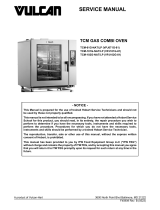
TEMPERATURE PROBE TEST
Disconnect the electrical power to
the machine and follow lockout /
tagout procedures.
NOTE: The temperature probe used in conjunction
with the Solid State Temperature control is an RTD
(resistance temperature detector) of the Thermistor
type. As temperature increases the resistance value
decreases.
1. Remove the Right Side Panel.
NOTE: If right side panel is not accessible, this
component can be serviced by removing the Control
Panel.
2. Place a shielded thermocouple in the geometric
center of the oven cavity and determine the
temperature in the oven cavity.
3. Remove the probe lead wires from the solid state
temperature control.
4. Test the probe with an ohmmeter.
A. If the measured resistance values are inside
the given tolerance then the probe is
functioning properly.
B. If the measured resistance values are
outside the given tolerance then replace the
probe and retest.
1) Check oven for proper operation.
5. Reverse procedure to install.
TEMP (°F) OHMS* TEMP (°F) OHMS*
77 90,000 360 822
240 4,077 380 656
260 3,016 400 529
280 2,266 425 424
300 1,726 450 334
320 1,332 475 266
340 1,041
(*) Resistance in ohms ± 10%
GAS VALVE PRESSURE CHECK
Disconnect the electrical power to
the machine and follow lockout /
tagout procedures.
1. Turn gas supply off at manual shutoff valve.
2. Remove the RIGHT SIDE PANEL.
NOTE: If right side panel is not accessible, this
component can be serviced by removing the
CONTROL PANEL.
3. Remove the plug from the manifold pressure
port.
WCGD FULL SIZE GAS CONVECTION OVEN - 3. SERVICE PROCEDURES AND ADJUSTMENTS
F45990 (1223) Page 20 of 41
/