Page is loading ...

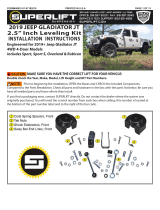
JEEP JK 3.5-6” FRONT CONTROL ARM RELOCATION KIT
Thank you for choosing Rough Country for your suspension needs.
Rough Country recommends a certified technician install this kit. In addition to these instructions, professional knowl-
edge of disassemble/reassembly procedures as well as post installation checks must be known. Attempts to install this
product without this knowledge and expertise may jeopardize the integrity and/or operating safety of the vehicle.
Please read instructions before beginning installation. Check the kit hardware against the parts list. Be sure you have all
needed parts and know where they go. Also please review tools needed list and make sure you have needed tools.
PRODUCT USE INFORMATION
Rough Country makes no claims regarding lifting devices and excludes any and all implied claims. We will not be re-
sponsible for any product that is altered. If question exist we will be happy to answer any questions concerning the de-
sign, function, and correct use of our products by calling 1-800-222-7023.
IMPORTANT NOTE : Upon completing the install of this kit the draglink must be adjusted to center the
steering wheel BEFORE the vehicle is driven. Failure to do so will cause a computer error, odd han-
dling, and poor performance.
NOTICE TO DEALER AND VEHICLE OWNER
Any vehicle equipped with any Rough Country product should have a “Warning to Driver” decal installed on the inside of
the windshield or on the vehicle’s dash. The decal should act as a constant reminder for whoever is operating the vehi-
cle of its unique handling characteristics.
INSTALLING DEALER - it is your responsibility to install the warning decal and forward these installation instructions on
to the vehicle owner for review. These instructions should be kept in the vehicle for its service life.
921106000
Tools Needed:
Jack Stands
Floor Jack
Reciprocating Saw
18mm Socket / Wrench
19mm Socket / Wrench
21mm Socket / Wrench
22mm Socket / Wrench
Torque Wrench
*110600BAG1*
110600BAG1
Torque Specs:
Size Grade 5 Grade 8
5/16” 15 ft/lbs 20 ft/lbs
3/8” 30 ft/lbs 35 ft/lbs
7/16” 45 ft/lbs 60 ft/lbs
1/2” 65 ft/lbs 90 ft/lbs
9/16” 95 ft/lbs 130 ft/lbs
5/8” 135 ft/lbs 175 ft/lbs
3/4” 185 ft/lbs 280 ft/lbs
Class 8.8 Class 10.9
6MM 5 ft/lbs 9 ft/lbs
8MM 18ft/lbs 23 ft/lbs
10MM 32ft/lbs 45ft/lbs
12MM 55ft/lbs 75ft/lbs
14MM 85ft/lbs 120ft/lbs
16MM 130ft/lbs 165ft/lbs
18MM 170ft/lbs 240ft/lbs

INSTALLATION INSTRUCTIONS
1. Chock the rear wheels.
2. Jack up the front of the vehicle and support with jack stands on the frame just rearward of the lower control arm
mounts.
3. Place a jack under the axle and lightly support the weigh of the axle.
4. On 2012 models the heat shield on the passenger side upper arm will need to be removed using a 10mm socket.
The heat shield will not be reused. Remove shield at this time. See Photos 1 & 2.
5. Loosen and remove the upper control arm bolt and flag nut on the frame and from the axle using a 18mm wrench.
See Photos 3 & 4. Retain the axle hardware as it will be reused.
6. The upper control arm frame bolt may have to be cut to be removed.
7. Loosen and remove the lower control arm hardware from the axle and frame using a 21mm wrench. Retain the fac-
tory hardware for the axle end only. See Photo 5.
8. Place the outer frame bracket (94004131 for Pass & 94004132 for Driver) in the upper frame mount using the sup-
plied .750” od sleeve and 12mm x 90mm bolts with the washer (on bolt head). See Photo 6.
Photo 1 Photo 2
Photo 3 Photo 4
Photo 5 Photo 6
Remove lower heat shield bolt. Remove upper heat shield bolt.
Loosen the upper control arm hardware. Remove the upper control arm hardware.
Loosen the lower control arm. Install the outer frame bracket in upper mount.

11. On the lower frame mount use the supplied .875” od sleeve and 14mm x 110mm bolt and washer. See Photo 7.
12. Place the inner frame bracket (94004133 for Pass & 94004134 for Driver) over the bolts using the 12mm flange lock
nut (Do not use a washer on the nut side) for the upper mount and the 14mm lock nut and washer on the lower
mount. Do not tighten at this time. See Photo 8.
13. Install the upper arm, using the factory hardware on the axle and the supplied 12mm x 90mm bolt, washer (bolt head
side only) and flange lock nut on the drop bracket. Do not tighten at this time. See Photo 9.
14. Install the lower control arm, using the factory hardware on the axle and the supplied cam bolt, washers, and nut on
the drop bracket. See Photo 10.
15. Repeat process on opposite side.
16. Reinstall the tires and wheels.
17. Jack up the vehicle and remove the jack stands.
18. Lower the vehicle to the ground.
19. Tighten all hardware at this time and torque using the torque chart on page 1.
20. Center the cam bolts.
21. Tighten the upper arm hardware using an 18mm on the nut & 19mm socket / wrench on the bolt.
22. Tighten the lower arm hardware using a 21mm on the nut & 22mm socket / wrench on the bolt.
POST INSTALLATION
1. Check all fasteners for proper torque. Check to ensure there is adequate clearance between all rotating, mobile,
fixed and heated members. Check steering for interference and proper working order. Test brake system.
2. Perform steering sweep. Cycle the steering from full turn to full turn to check for clearance. Failure to perform in-
spections may result in component failure.
3. The draglink must be adjusted to the center steering wheel BEFORE the vehicle is driven. Failure to do so will
cause a computer error with the Jeeps traction control system and result in odd handling and poor performance.
4. Using an certified alignment professional with experience in aligning lifted vehicles, get an alignment done to factory
specifications.
Photo 7 Photo 8
Install the outer frame bracket in lower mount. Install the inner frame bracket.
Photo 9 Photo 10
Install the upper control arm. Install the lower control arm.

KIT CONTENTS
Kit Contents:
1-Driver Side Inner Bracket
1-Driver Side Outer Bracket
1-Pass Side Inner Bracket
1-Pass Side Outer Bracket
2-Upper Crush Sleeves
2-Lower Crush Sleeves
2-Lower Arm Cam Bolt Kits
Poly Bag:
2-14mm X 110mm Bolts
2-14mm Lock Nuts
4-Flat Washers
4-12mm x 90mm Bolts
4-12mm Flange Lock nuts
4-Flat Washers
By purchasing any item sold by Rough Country, LLC, the buyer expressly warrants that he/she is in compliance with all
applicable , State, and Local laws and regulations regarding the purchase, ownership, and use of the item. It shall be
the buyers responsibility to comply with all Federal, State and Local laws governing the sales of any
items listed, illustrated or sold. The buyer expressly agrees to indemnify and hold harmless Rough
Country, LLC for all claims resulting directly or indirectly from the purchase, ownership, or use of the
items.
/