Page is loading ...

AA-4104
2018-PRESENT
AIR SUSPENSION SYSTEM
JEEP WRANGLER (JL)
INSTALLATION GUIDE

The suspension of this vehicle has been optimized for off road utility through installation of an AccuAir® system allowing
control/adjustment of ride height to accommodate challenging terrain & obstacles. The suspension feel and handling maybe
different than an unmodified Jeep.
To reduce risk of roll-over other accident & serious injury always:
• Inspect components including bags, lines, valves & compressor before use, followed by system self-test. Maintain & repair
as indicated. On road height limited to approx. 3.0” by system speed & ride height sensors. REPLACE & DO NOT USE ON
ROAD IF SPEED SENSOR DAMAGED/INOPERATIVE.
CONGRATULATIONS!
A FEW WORDS ABOUT PRODUCT SAFETY
Your AccuAir® Jeep JL Air Suspension system reflects a unique solution to balancing
enhanced off road terrain and obstacle clearance with everyday drivability and ride quality.
The AccuAir® JL system features remote mounted dual ENDO storage tanks, a quality
compressor, mounts and all fittings necessary to replace your coil springs with ruggedly
designed four corner air bags allowing you to select a ride height tailored to your off
road adventures. Back on the road, a unique speed sensing value presets ride height to
a maximum of 3.0” of lift (approx.), helping to preserve familiar ride comfort. Enjoy your
AccuAir® JL system by Treading Lightly© and following all instructions and product safety
messaging below. If you have further questions contact us at: sales@AccuAir.com. Our
team is here to help.
• The drag link must be adjusted to center the steering wheel before the vehicle is driven. Failure to do so will cause
computer errors, odd handling characteristics, and poor performance.
• If larger tires (10% more than the OEM diameter) are installed, speedometer recalibration will be necessary.
Contact your local Jeep dealer.
• After installation, a qualified alignment facility is required to align the vehicle to the OEM specification.
• DO NOT modify or substitute AccuAir® components of
this system. Use of oversize tire/wheel combinations
may increase stopping distances, ride height and/or
compromise performance of vehicle stability control and
other systems.
• Avoid excessive speeds, abrupt maneuvers, surfaces/
obstacles which may induce a tripping moment. All
occupants BUCKLE UP & USE supplemental restraints.
• Consult the AccuAir® installation manual
(sales@AccuAir.com) & OEM off road supplement for
additional safety information.
Before installation, please take a moment to review the following safety information and installation instructions.
Important safety information is generally preceded by one of three signal words indicating the relative risk of injury.
The signal words mean:
If you have any questions or reservations about installing this product, contact AccuAir Customer Service.
WARNING:
A hazardous situation which, if not avoided, could result in death or serious injury. You CAN be killed or seriously
hurt if you don’t follow instructions.
WARNING:
This advanced AccuAir® JL kit requires professional installation, with access to vehicle lift and experience with Jeep JL
suspension, electrical wiring, Jeep maintenance recommendations, safety messaging, torque & other specifications,
general repair safety including personal protection, vehicle rack safety, isolation and containment of OEM spring
assemblies during removal.
WARNING:
Incorrect shock length will distort air bag placement and lead to burst or reduced service life. USE front and rear
shock absorbers included with this kit.
Replacement shocks must be FRONT: 26.125” (allowed variance .125”); REAR: 27.72” (allowed variance .125”).
CAUTION:
A hazardous situation which, if not avoided, could result in minor or moderate injury. You CAN be moderately hurt
and may also suffer property damage if you do not follow instructions. CAUTION:
Risk of Eye Injury. Safety glasses, gloves & other personnel protection should be worn when working with this product.
NOTICE:
Careful attention is required to this instruction or operation but does generally not relate to personal injury. Damage to
your AccuAir® product or other property may result if you don’t follow instructions.
NOTICE:
Never lower vehicle from rack or following inspection/
repair without air bags being fully inflated. CANCER AND REPRODUCTIVE HARM
WWW.P65WARNING.CA.GOV
WARNING
WARNING:SUSPENSION MODIFIED WITH VARIABLE
HEIGHT AIRBAGS - HIGHER ROLLOVER RISK
Inspect Components Followed by
System Self-test.
DO NOT Modify or Substitue AccuAir®
Components of This System.
Avoid Excessive Speeds, Abrupt
Maneuvers, Surfaces/Obstacles
Which May Induce a Tipping Moment.
Always Buckle Up.
See AccuAir® Installation
Manual & OEM Off Road
Supplement for Additional
Safety Information
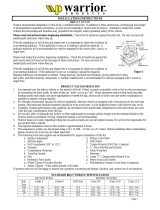
Affix warning decal on driver’s side visor in clear view of all occupants.
WATCH THIS VIDEO
FOR A COMPLETE
SYSTEM OVERVIEW
1 2AA-3924 Installation Manual REV 01 | 11/03/2022
PRODUCT & INSTALLATION OVERVIEW

3 4AA-3924 Installation Manual REV 01 | 11/03/2022
ACCUAIR® SUSPENSION LIMITED WARRANTY
WHAT IS COVERED?:
Subject to the terms, exclusions and limitations herein, Arnott, LLC. (“Warrantor” or “AccuAir”) exclusively warrants
to the initial retail purchaser of a AccuAir Jeep JL suspension kit that AccuAir will according to terms herein, repair
defects in or replace AccuAir supplied components which, upon AccuAir inspection are determined to have defects
in materials or workmanship existing as of the date of sale to the initial retail customer (hereafter “Customer”). This
Limited Warranty is the sole and exclusive warranty made or authorized by Warrantor. This Limited Warranty is not a
warranty or promise of any particular future performance.
The term of this Limited Warranty shall be three years as measured from the date of sale to initial Customer (the
warranty “TERM”). Any claim under this limited warranty must be made within six months of the last day of the
warranty TERM or will be forever waived. The duration of any implied warranty shall be limited to the three year term
of express limited warranty above.
WHAT IS NOT COVERED?:
Your AccuAir Limited Warranty does not cover: (1) defect in a AccuAir air suspension kit or component causing or
contributing to damage or defect, of any type whatsoever, to the vehicle it is installed upon or any electrical system
or other vehicle system or component separately warranted or supplied by a manufacturer other than AccuAir, (2)
damage to AccuAir components or your vehicle from altering or disabling any component of your vehicle or AccuAir
product; additions, alterations, or other products or components not supplied by AccuAir, (3) installation or use
contrary to professional installation recommendations, or other installation/use contrary to instructions and safety
messaging included within your AccuAir product, (4) expected wear and tear on airbags and other components
considering vehicle use, damage related to failure to adequately, install, inspect, maintain, adjust or service as
recommended or required, damage resulting from improper suspension set-up, loading, accident, collision, vandalism,
abuse, misuse, neglect, fire, flood, normal wear, defects in or degradation of finishes, reflecting corrosion, UV or
other environmental influences (5), AccuAir, components used in competition, other off road use or events which
may involve unforeseen vehicle components, suspension set ups, contact between vehicles, rocks or obstacles, other
components of your vehicle and your AccuAir components, damage or degradation of performance, (6) labor, lost time,
lost use or opportunities, reasonable delays in remedies hereunder, other consequential, incidental, punitive or other
damages or costs, including those incurred in removing, reinstalling or delivering your AccuAir component to AccuAir for
inspection, repair or replacement.
OBTAINING WARRANTY & CUSTOMER SERVICE:
Register your AccuAir Purchase. For questions or claims contact AccuAir Customer Service: 100 Sea Ray Drive,
Merritt Island, FL 32953. You will be asked to advise AccuAir in writing of your understanding of all defects and
provide AccuAir an opportunity to repair or replace the affected component(s) subject to the terms of this Limited
Warranty. Please have proof of purchase available.
REMEDY LIMITED TO REPAIR/REPLACEMENT BY ACCUAIR. BINDING, SINGLE CLAIM ARBITRATION-VENUE:
Upon Customer’s removal and delivery to AccuAir for inspection and AccuAir determination of a covered defect,
the exclusive remedy provided hereunder shall at AccuAir’s option be repair or replacement of the defective AccuAir
component(s). Your sole and exclusive remedy for breach of this Limited Warranty or any implied warranty imposed
by law, is the reasonable costs for replacement parts necessary to correct the defect(s) upon which the finding of
breach is based. For separate, valuable consideration received; all claims arising from or related to purchase or use of
AccuAir components shall exclusively be maintained as a separate action by each Customer applying Florida state law
(without reference to treaties or conflict of law provisions) through binding arbitration before a neutral selected by
Customer from the JAMS® panel closest to Merritt Island, Florida. To the extent permitted by law, each party shall bear
its own costs and fees. Any claim to enforce an arbitration award or for other breach or damages under this Limited
Warranty can only be brought in a court of competent jurisdiction closest to Brevard County, Florida.
OTHER EXCLUSIONS –LIMITATION OF DAMAGES - YOUR RIGHTS UNDER STATE LAW.
No employee, other agent of AccuAir or authorized reseller may, amend or waive this written Limited Warranty
or make additional representations or warranties regarding any AccuAir features, performance, workmanship or
materials. AccuAir reserves the right to make changes in design and changes or improvements upon its products
without imposing any obligation on itself to install or upgrade the same upon products previously manufactured.
By installation and use of your AccuAir product, and/or submitting a claim under this Limited Warranty, you
acknowledge that you have received and understand all product instructions, warnings and this Limited Warranty
and agree to be bound by all terms therein, reflecting the exclusive terms and remedies of the parties bargain.
This Limited Warranty gives you specific rights. You may also have other rights that vary from state to state. For
example, some states do not allow limitations of how long an implied warranty lasts and/or do not allow the exclusion
or limitation of incidental or consequential damages, so the limitations and exclusions herein may not apply to you. All
other warranties are hereby disclaimed, except to the extent prohibited by applicable law.

INDEX
Wire Routing, Fuse Box, Speed Module Routing & Plumbing Routing Diagrams 5
Wiring 13
Plumbing & Routing 25
Final Interior Installation 31
Front Installation 34
Rear Installation 49
Final Clearance Check & Torque Steps 64
Troubleshooting & Technical Support 66
INCLUDED PARTS
Air Suspension Conversion Kit VIAIR Inflation System
JRi Custom Tuned Shocks Front Lower Control Arms
e+ Connect Rear Upper and Lower Control Arms
TouchPad+ Upgrade Adjustable Front Track Bar
Height+ Front and Rear Sway Bar End Links
Height Sensor Brackets Front and Rear Brake Line Extension Brackets
VU4 4-Corner Manifold Install Kit for ECU, Air Tank, Compressor
3 Gallon Seamless Tank Air Compressor Bracket
VIAIR 485C Compressor
REQUIRED TOOLS
SAE & SAE Hex Key Sockets/Wrenches Metric & Metric Hex Key Sockets/Wrenches
(5/32”, 7/32” & 5/16” Hex Key Sockets, 7/16”, 1/2”,
9/16”, 3/4”, 13/16”, 7/8” & 1-1/8”)
(6mm Hex Key Socket, 8mm, 10mm, 13mm, 15mm,
18mm, 19mm, 21mm, 22mm & 24mm)
Measuring Tape Jack Stands Ball Peen Hammer Floor Jack
Safety Glasses Pliers Wheel Chock Torque Wrench
5 6AA-3924 Installation Manual REV 01 | 11/03/2022
INDEXINCLUDED PARTS

Front
Rear
F106
F92
F93
F109
F99
F96
F91
F89
F60
F44
CB01
F61
F62
F56
F55
F57
F58
F40
F39
F41
F42
F47
F46
F48
F49
F05
F04
F06
F07
F08
F09
F10
F11
F12
F18
F19
F13
F14
F15
F33
F32 F23
F22
F01
F03
F34
F51
F50
F31 F25
F52
F53
F45 F43
F87
K21 K20
K04 K02
CB02
F82 F59
F73
F84
F74
F83 F65
F66
F36
F37
F38
F24F30
CB03
K16
K15
K14
K13
K12
K11
K08 K05
K06
K03 K01
K09
K10 K07
F16
F17
F111
F110
F100
F101
F107
F104
F102
F97
F94
F94
F79
F85
F80
F76
F70
F67
F63
F35
F29
F28
F26
F20
F75
F108
F105
F103
F98
F95
F95
F88
K17
K18
K19
F68
F81
F78
F72
F69
F77
F71
F64
F54
F21
F27
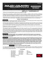
F02 Manifold
ECU
Purge
Valve
Battery & ECU
Chassis
Ground
ECU
Compressor
Output
Compressor
Input to
Headlight
(Optional)
Relay
Touchpad
(Route to Vehicle Cabin)
Fuse
(70 AMP)
Ride Height
Sensor - 4
Rear Right
Ride Height
Sensor - 3
Rear Left
Ride Height
Sensor - 2
Front Right
Ride Height
Sensor - 1
Front Left
Pressure Sensor
Comp
87
86
85
30
Bolt Ground lug
(under vehicle)
Ground Lug
(in vehicle)
Battery Fuse Box
(Ignition
Fuse Tap
- F52)
5 6AA-3924 Installation Manual REV 01 | 11/03/2022
WIRE ROUTING

F106
F92
F93
F109
F99
F96
F91
F89
F60
F44
CB01
F61
F62
F56
F55
F57
F58
F40
F39
F41
F42
F47
F46
F48
F49
F05
F04
F06
F07
F08
F09
F10
F11
F12
F18
F19
F13
F14
F15
F33
F32 F23
F22
F01
F03
F34
F51
F50
F31 F25
F52
F53
F45 F43
F87
K21 K20
K04 K02
CB02
F82 F59
F73
F84
F74
F83 F65
F66
F36
F37
F38
F24F30
CB03
K16
K15
K14
K13
K12
K11
K08 K05
K06
K03 K01
K09
K10 K07
F16
F17
F111
F110
F100
F101
F107
F104
F102
F97
F94
F94
F79
F85
F80
F76
F70
F67
F63
F35
F29
F28
F26
F20
F75
F108
F105
F103
F98
F95
F95
F88
K17
K18
K19
F68
F81
F78
F72
F69
F77
F71
F64
F54
F21
F27
F02
TAP INTO TAP INTO F52F52
7 8AA-3924 Installation Manual REV 01 | 11/03/2022
FUSE BOX

Front
Rear
F106
F92
F93
F109
F99
F96
F91
F89
F60
F44
CB01
F61
F62
F56
F55
F57
F58
F40
F39
F41
F42
F47
F46
F48
F49
F05
F04
F06
F07
F08
F09
F10
F11
F12
F18
F19
F13
F14
F15
F33
F32 F23
F22
F01
F03
F34
F51
F50
F31 F25
F52
F53
F45 F43
F87
K21 K20
K04 K02
CB02
F82 F59
F73
F84
F74
F83 F65
F66
F36
F37
F38
F24F30
CB03
K16
K15
K14
K13
K12
K11
K08 K05
K06
K03 K01
K09
K10 K07
F16
F17
F111
F110
F100
F101
F107
F104
F102
F97
F94
F94
F79
F85
F80
F76
F70
F67
F63
F35
F29
F28
F26
F20
F75
F108
F105
F103
F98
F95
F95
F88
K17
K18
K19
F68
F81
F78
F72
F69
F77
F71
F64
F54
F21
F27
F02
ECU
Relay
Fuse Box
(Ignition
Fuse Tap
- F52)
OBD II Port
Ignition Wire Tap
Speed
Module
9 10AA-3924 Installation Manual REV 01 | 11/03/2022
SPEED MODULE ROUTING

Front
Rear
Air Spring - 1
Front Left
Air Spring - 2
Front Right
ViAIR
Compressor
Intake Filter
Air Spring - 3
Rear Left
Air Spring - 4
Rear Right
Manifold
Regulator
Air Line
Union
Air Line
Union
Residual
Pressure Union
Residual
Pressure Union
11 12AA-3924 Installation Manual REV 01 | 11/03/2022
PLUMBING ROUTING

1. Take the 6 gauge power wire with the 70 AMP fuse installed from the box labeled AA-4102. (Figure 1)
Lay the fuse on top of the battery and route remaining wire along the passenger side frame rail to the floor drain
plug underneath the center of the vehicle (Figure 2). Do not connect to battery at this time.
FIGURE 1
FIGURE 2
2. Remove the floor pan drain plug from underneath the center of the vehicle. (Figure 3)
FIGURE 3
3. Install the provided rubber grommet in the floor pan hole. (Figure 4)
FIGURE 4
13 14AA-3924 Installation Manual REV 01 | 11/03/2022
WIRING

4. Pull the ECU main harness plug, valve harness plug, compressor power cable, batter power cable, and height sensor
harness plug into the cab via the grommeted floor pan hole. Run an end of the 1/4” air line for the pressure regulator
into the cab via the grommeted floor pan hole. (Figure 5)
FIGURE 5
5. Inside the cab, fold the rear seats forward. Gather and pull the wires, tubing, and ground connections, up from the
grommeted floor pan hole. (Figure 6)
FIGURE 6
6. Remove rear driver’s side carpet, and move wiring connectors and tube on the rear driver’s side body panel. Install
ground rings for ECU, relay, and speed module cable ground wires. Secure rings on body grounding stud with standoff
(Standoff found in box AA-4021). (Figure 7)
FIGURE 7
15 16AA-3924 Installation Manual REV 01 | 11/03/2022
WIRING

7. Install heat shrink onto wire end and crimp copper ring terminal onto battery power cable. (Use the ring terminal with
flat sides.) (Found in box AA-4102.) (Figure 8)
8.
FIGURE 8
Crimp ring terminal onto ECU power flying lead. (Figure 9)
FIGURE 9
9. Gather all wire harnesses and the regulator air tubing and bundle them behind the carpet. Also add TouchPad cable
(white connector). (Figure 10)
FIGURE 10
10. Grab ECU bracket from box labeled AA-4021. Make electrical connections as shown below. Refer to relay diagram to
make relay connections. (Figure 11)
FIGURE 11
17 18AA-3924 Installation Manual REV 01 | 11/03/2022
WIRING

11. Install the large bracket holding the seamless tank, compressor, and VU4 manifold to the frame underneath
the vehicle using the provided mounting hardware. The tank will face forward toward the engine bay, while the
compressor and VU4 valve block will face the rear of the vehicle. (Figure 12)
FIGURE 12
12. Feed the compressor power cable up through the floor drain hole and connect to red male quick terminal from the
relay. (Figure 13)
FIGURE 13
13. Run the orange ignition wire from the ECU and the black 2-pin connector under the driver side kick panel toward the
driver floorboard. (Figure 14)
FIGURE 14
14. Route the orange ignition wire from the driver side kick panel up to the fuse box under the hood on the passenger
side. (Figure 15)
FIGURE 15
19 20AA-3924 Installation Manual REV 01 | 11/03/2022
WIRING

15. Crimp the orange ignition wire to the fuse tap provided in AA-4102. Extract 20 AMP fuse from F52 and place on
bottom position of the fuse tap. Pull the spare 5 (or 10) AMP fuse and position in top slot of the fuse tap. (Figure 16)
16.
FIGURE 16
Remove the fuse in position (F52) and install the fuse tap. (Figure 17)
FIGURE 17
SPEED MODULE
VIDEO
17. Install the speed module using hardware from the box labeled AA-4103.
The supplied speed module must be installed to allow full functionality of the system.
View video using QR code to the right for installation process.
18. Underneath the vehicle on the bracket, connect the VU4 harness. (Figure 18)
FIGURE 18
21 22AA-3924 Installation Manual REV 01 | 11/03/2022
WIRING

19. Connect the purge valve. (Figure 19)
FIGURE 19
20. Connect the 3-wire pressure sensor. (Figure 20)
FIGURE 20
21. Connect ground ring terminals for valve harness, compressor, and purge valve to the under-body ground lug. (Figure 21)
FIGURE 21
23 24AA-3924 Installation Manual REV 01 | 11/03/2022
WIRING

1. Plumb air lines according to the diagram below.
Front
Rear
Air Spring - 1
Front Left
Air Spring - 2
Front Right
ViAIR
Compressor
Intake Filter
Air Spring - 3
Rear Left
Air Spring - 4
Rear Right
Manifold
Regulator
Air Line
Union
Air Line
Union
Residual
Pressure Union
Residual
Pressure Union
2. Make VU4 connections as shown. Note the port to corner association with Figure 22 and plumbing diagram. (Figure 22)
1
1
2
2
3
3
4
4
FIGURE 22
3. Connect 1/4” regulator air line to elbow on the front of the tank. (Figure 23)
FIGURE 23
25 26AA-3924 Installation Manual REV 01 | 11/03/2022
PLUMBING/ROUTING

4. Trim and attach 1/4” air line to regulator. (Figure 24)
5.
FIGURE 24
Install intake filter near engine intake in the front passenger side under the hood. (Figure 25)
FIGURE 25
6. Route the intake line back to the compressor. (Figure 26)
FIGURE 26
27 28AA-3924 Installation Manual REV 01 | 11/03/2022
PLUMBING/ROUTING

8. Next, locate the TouchPad user interface where you want it to be in the vehicle (typically near center console).
Ensure the cable is routed appropriately for your chosen location. (Figure 27)
FIGURE 27
7. Route height sensors to wheel wells according to the diagram below. Ensure harness numbers are going to the
correct corners “1, 2, 3, and 4”.
Front
Rear
F106
F92
F93
F109
F99
F96
F91
F89
F60
F44
CB01
F61
F62
F56
F55
F57
F58
F40
F39
F41
F42
F47
F46
F48
F49
F05
F04
F06
F07
F08
F09
F10
F11
F12
F18
F19
F13
F14
F15
F33
F32 F23
F22
F01
F03
F34
F51
F50
F31 F25
F52
F53
F45 F43
F87
K21 K20
K04 K02
CB02
F82 F59
F73
F84
F74
F83 F65
F66
F36
F37
F38
F24F30
CB03
K16
K15
K14
K13
K12
K11
K08 K05
K06
K03 K01
K09
K10 K07
F16
F17
F111
F110
F100
F101
F107
F104
F102
F97
F94
F94
F79
F85
F80
F76
F70
F67
F63
F35
F29
F28
F26
F20
F75
F108
F105
F103
F98
F95
F95
F88
K17
K18
K19
F68
F81
F78
F72
F69
F77
F71
F64
F54
F21
F27
F02 Manifold
ECU
Purge
Valve
Battery & ECU
Chassis
Ground
ECU
Compressor
Output
Compressor
Input to
Headlight
(Optional)
Relay
Touchpad
(Route to Vehicle Cabin)
Fuse
(70 AMP)
Ride Height
Sensor - 4
Rear Right
Ride Height
Sensor - 3
Rear Left
Ride Height
Sensor - 2
Front Right
Ride Height
Sensor - 1
Front Left
Pressure Sensor
Comp
87
86
85
30
Bolt Ground lug
(under vehicle)
Ground Lug
(in vehicle)
Battery Fuse Box
(Ignition
Fuse Tap
- F52)
29 30AA-3924 Installation Manual REV 01 | 11/03/2022
PLUMBING/ROUTING

1. Cut carpet for bracket clearance. (Figure 28)
FIGURE 28
2. Tighten forward hex. (Figure 29)
FIGURE 29
3. Tighten Allen fastener to standoff. (Figure 30)
FIGURE 30
4. When completed, ECU bracket should look as shown. (Figure 31)
FIGURE 31
31 32AA-3924 Installation Manual REV 01 | 11/03/2022
FINAL INTERIOR INSTALLATION

5. Terminate the short leg of the power cable. Remove the 70 AMP fuse from the holder. Connect the cable to the
battery. Then, reinstall the 70 AMP fuse. (Figure 32)
FIGURE 32
1. With vehicle on flat level ground, set emergency brake & chock rear tires/wheels.
2. Raise front of vehicle. Support frame rails using jack stands at indicated lift points in OEM service manual.
3. Remove the front tires/wheels using a 22mm socket.
4. Remove OEM front skid plate using a 13mm socket/wrench. (Figure 33)
FIGURE 33
5. Remove OEM front sway bar end links using a 6mm hex key socket/wrench & 18mm socket/wrench. (Figure 34)
FIGURE 34
33 34AA-3924 Installation Manual REV 01 | 11/03/2022
FRONT INSTALLATIONFINAL INTERIOR INSTALLATION

8. Disconnect OEM front shock from upper shock tower mount & lower axle mount using a 18mm socket/wrench.
(Figure 37)
FIGURE 37
9. Disconnect OEM front brake line brackets from OEM front lower control arms using a 15mm socket/wrench.
(Figure 38)
FIGURE 38
6. Disconnect OEM front track bar from frame using a 21mm socket/wrench. (Figure 35)
FIGURE 35
7. Disconnect OEM drag link from OEM pitman arm using a 21mm socket/wrench. (Figure 36)
FIGURE 36
35 36AA-3924 Installation Manual REV 01 | 11/03/2022
FRONT INSTALLATION
1/36