Page is loading ...

921668300E
Thank you for choosing Rough Country for your suspension needs.
Rough Country recommends a certified technician install this system. In addition to these instructions, professional
knowledge of disassemble/reassembly procedures as well as post installation checks must be known. Attempts to install
this system without this knowledge and expertise may jeopardize the integrity and/or operating safety of the vehicle.
Please read instructions before beginning installation. Check the kit hardware against the parts list. Be sure you have all
needed parts and know where they go. Also please review tools needed list and make sure you have needed tools.
PRODUCT USE INFORMATION
As a general rule, the taller a vehicle is, the easier it will roll. Seat belts and shoulder harnesses should
be worn at all times. Avoid situations where a side rollover may occur.
Generally, braking performance and capability are decreased when larger/heavier tires and wheels are used. Take this
into consideration while driving. Do not add, alter, or fabricate any factory or after-market parts to increase vehicle height
over the intended height of the Rough Country product purchased. Mixing component brands is not recommended.
Rough Country makes no claims regarding lifting devices and excludes any and all implied claims. We will not be re-
sponsible for any product that is altered.
This suspension system was developed using a 35x12.50x20 tire on a 20x10 wheel with -18 offset. Different wheel and
tire combinations my be used but different tire manufactures designs may result in a tire width that could result in contact
with the lower control arm and/or front sway bar link in a sharp turn. Please consult with your tire and wheel expert be-
fore purchasing. Also note that if wider tires are desired, offset wheels will be required. If question exist we will be happy
to answer any questions concerning the design, function, and correct use of our products by calling 1-800-222-7023.
NOTICE TO DEALER AND VEHICLE OWNER
Any vehicle equipped with any Rough Country product should have a “Warning to Driver” decal installed on the inside of
the windshield or on the vehicle’s dash. The decal should act as a constant reminder for whoever is operating the vehi-
cle of its unique handling characteristics.
JEEP JL (GAS) Standard and 392 3.5” Stage 1 Control Arm Drop Kit
JEEP JL (Diesel) 3” Stage 1 Control Arm Drop Kit
Tools Needed:
6mm Allen
8mm Socket & Wrench
10mm Socket & Wrench
15mm Socket & Wrench
18mm Socket & Wrench
21mm Socket & Wrench
22mm Deep Well Socket
24mm Socket & Wrench
Pliers
7/16” Socket & Wrench
9/16” Socket & Wrench
5/8” Socket & Wrench
3/4” Socket & Wrench
13/16” Socket & Wrench
Jack
15/32” Drill
Drill Motor
Jack Stands
Torque Wrench
Torque Specs:
Size Grade 5 Grade 8
5/16” 15 ft/lbs 20 ft/lbs
3/8” 30 ft/lbs 35 ft/lbs
7/16” 45 ft/lbs 60 ft/lbs
1/2” 65 ft/lbs 90 ft/lbs
9/16” 95 ft/lbs 130 ft/lbs
5/8” 135 ft/lbs 175 ft/lbs
3/4” 185 ft/lbs 280 ft/lbs
Class 8.8 Class 10.9
6MM 5 ft/lbs 9 ft/lbs
8MM 18ft/lbs 23 ft/lbs
10MM 32ft/lbs 45ft/lbs
12MM 55ft/lbs 75ft/lbs
14MM 85ft/lbs 120ft/lbs
16MM 130ft/lbs 165ft/lbs
18MM 170ft/lbs 240ft/lbs

66830

66830 KIT CONTENTS 78130 KIT CONTENTS
Kit Box 66830BOX2
Qty Description
1 Front Forged Adj. Track Bar
2 Front Bump Stop Spacers
2 Rear Bump Stop Spacers
1 Dr Outer Control Arm Drop Bracket
1 Pass Outer Control Arm Drop Bracket
1 Dr Inner Control Arm Drop Bracket
1 Pass Inner Control Arm Drop Bracket
2 Front Sway Bar Links
2 Rear Sway Bar Links
2 Rear Sway Bar Spacers
1 Rear Track Bar Bracket
1 66830BAG3 Instruction Bag
1 65431BAG6 Hardware Bag
1 66830BAG2 Hardware Bag
1 65431BAG4 Control Arm Drop Bag
1 1609BAG6 Rear Bump Stop Bag
1 1609BAG7 Front Bump Stop Bag
Kit Box 67830BOX1
Qty Description
2 Front Coil Springs
2 Rear Coil Springs
23217 Front N3 Shocks
Qty Description
2 660808 Front N3 Shocks
23216 Rear N3 Shocks
Qty Description
2 660807 Rear N3 Shocks
Kit Box 66830BOX2
Qty Description
1 Front Forged Adj. Track Bar
2 Front Bump Stop Spacers
2 Rear Bump Stop Spacers
1 Dr Outer Control Arm Drop Bracket
1 Pass Outer Control Arm Drop Bracket
1 Dr Inner Control Arm Drop Bracket
1 Pass Inner Control Arm Drop Bracket
2 Front Sway Bar Links
2 Rear Sway Bar Links
2 Rear Sway Bar Spacers
1 Rear Track Bar Bracket
1 66830BAG3 Instruction Bag
1 65431BAG6 Hardware Bag
1 66830BAG2 Hardware Bag
1 65431BAG4 Control Arm Drop Bag
1 1609BAG6 Rear Bump Stop Bag
1 1609BAG7 Front Bump Stop Bag
23217 Front N3 Shocks
Qty Description
2 660808 Front N3 Shocks
23218 Rear N3 Shocks
Qty Description
2 660809 Rear N3 Shocks
Kit Box 9420
Qty Description
2 Front Coil Springs
Kit Box 9403
Qty Description
2 Rear Coil Springs

66850 KIT CONTENTS
Kit Box 66830BOX2
Qty Description
1 Front Forged Adj. Track Bar
2 Front Bump Stop Spacers
2 Rear Bump Stop Spacers
1 Dr Outer Control Arm Drop Bracket
1 Pass Outer Control Arm Drop Bracket
1 Dr Inner Control Arm Drop Bracket
1 Pass Inner Control Arm Drop Bracket
2 Front Sway Bar Links
2 Rear Sway Bar Links
2 Rear Sway Bar Spacers
1 Rear Track Bar Bracket
1 66830BAG3 Instruction Bag
1 65431BAG6 Hardware Bag
1 66830BAG2 Hardware Bag
1 65431BAG4 Control Arm Drop Bag
1 1609BAG6 Rear Bump Stop Bag
1 1609BAG7 Front Bump Stop Bag
Kit Box 67830BOX1
Qty Description
2 Front Coil Springs
2 Rear Coil Springs
680007 Front Vertex Shocks
Qty Description
2 Front Vertex Shocks
690007R Right Rear Vertex Shock
Qty Description
1 Right Rear Vertex Shock
690007L Left Rear Vertex Shock
Qty Description
1 Left Rear Vertex Shock

66870 KIT CONTENTS
Kit Box 66830BOX2
Qty Description
1 Front Forged Adj. Track Bar
2 Front Bump Stop Spacers
2 Rear Bump Stop Spacers
1 Dr Outer Control Arm Drop Bracket
1 Pass Outer Control Arm Drop Bracket
1 Dr Inner Control Arm Drop Bracket
1 Pass Inner Control Arm Drop Bracket
2 Front Sway Bar Links
2 Rear Sway Bar Links
2 Rear Sway Bar Spacers
1 Rear Track Bar Bracket
1 66830BAG3 Instruction Bag
1 65431BAG6 Hardware Bag
1 66830BAG2 Hardware Bag
1 65431BAG4 Control Arm Drop Bag
1 1609BAG6 Rear Bump Stop Bag
1 1609BAG7 Front Bump Stop Bag
Kit Box 67830BOX1
Qty Description
2 Front Coil Springs
2 Rear Coil Springs
760808 Front V2 Shocks
Qty Description
2 Front V2 Shocks
760807 Rear V2 Shocks
Qty Description
2 Rear V2 Shocks

65431BAG6
Qty Description
4 1/2” Flat Washers
4 12mm x 65mm Bolt
4 12mm Flange Locknut
4 10mm x 55mm Bolts
4 10mm Lock Washers
4 10mm Flat Washers
1 14mm x 80mm Bolt
1 9/16” Flat Washer
1 14mm Nylock Nut
1 Rear Track Bar 15mm OD Sleeve
3 7/16” x 1.25” Bolts
6 7/16” Flat Washers
3 7/16” Nylock Nuts
65431BAG4– Control Arm Drop
Qty Description
2 Upper Control Arm Drop Sleeves
2 Lwr Control Arm Drop Sleeves
2 12mm x 80mm Bolts
2 1/2” Flat Washers
2 12mm Flange Lock Nuts
2 16mm Cam Bolts
4 Cam Washers
2 16mm Nylock Nuts
2 16mm Flat Washers
1609BAG6
Qty Description
4 3/8” Flat Washer
4 3/8” x .75” Bolt
4 3/8” Flange Lock Nut
1609BAG7
Qty Description
2 3/8” Flat Washer
2 3/8” x 3” Bolt
2 3/8” Flange Lock Nut
66830BAG2
Qty Description
1 Dr Brake Line Bracket
1 Pass Brake Line Bracket
2 1/4” x 1” Bolts
2 1/4” Nylock Nuts
4 1/4” Flat Washers

60600

60600 KIT CONTENTS
5093.1
Qty Description
1 Drive Shaft
Kit Box 66830BOX2
Qty Description
1 Front Forged Adj. Track Bar
2 Front Bump Stop Spacers
2 Rear Bump Stop Spacers
1 Dr Outer Control Arm Drop Bracket
1 Pass Outer Control Arm Drop Bracket
1 Dr Inner Control Arm Drop Bracket
1 Pass Inner Control Arm Drop Bracket
2 Front Sway Bar Links
2 Rear Sway Bar Links
2 Rear Sway Bar Spacers
1 Rear Track Bar Bracket
1 65431BAG6 Hardware Bag
1 66830BAG2 Hardware Bag
1 65431BAG4 Control Arm Drop Bag
1 1609BAG6 Rear Bump Stop Bag
1 1609BAG7 Front Bump Stop Bag
60600991
Qty Description
2 94004259 - Front Shock Brackets
2 94004267 - Rear Shock Brackets
1 60600BAG1 - Hardware Bag
Kit Box 9453
Qty Description
2 Front Coil Springs
Kit Box 9454
Qty Description
2 Rear Coil Springs

65431BAG6
Qty Description
4 1/2” Flat Washers
4 12mm x 65mm Bolt
4 12mm Flange Locknut
4 10mm x 55mm Bolts
4 10mm Lock Washers
4 10mm Flat Washers
1 14mm x 80mm Bolt
1 9/16” Flat Washer
1 14mm Nylock Nut
1 Rear Track Bar 15mm OD Sleeve
3 7/16” x 1.25” Bolts
6 7/16” Flat Washers
3 7/16” Nylock Nuts
65431BAG4– Control Arm Drop
Qty Description
2 Upper Control Arm Drop Sleeves
2 Lwr Control Arm Drop Sleeves
2 12mm x 80mm Bolts
2 1/2” Flat Washers
2 12mm Flange Lock Nuts
2 16mm Cam Bolts
4 Cam Washers
2 16mm Nylock Nuts
2 16mm Flat Washers
1609BAG6
Qty Description
4 3/8” Flat Washer
4 3/8” x .75” Bolt
4 3/8” Flange Lock Nut
1609BAG7
Qty Description
2 3/8” Flat Washer
2 3/8” x 3” Bolt
2 3/8” Flange Lock Nut
66830BAG2
Qty Description
1 Dr Brake Line Bracket
1 Pass Brake Line Bracket
2 1/4” x 1” Bolts
2 1/4” Nylock Nuts
4 1/4” Flat Washers
60600BAG1
Qty Description
2 3/8” Flange Lock Nuts
2 3/8” Flat Washers
2 3/8” x 1 Bolts
2 1/2” Lock Nuts
2 1/2” x 1-1/4” Bolts
4 12mm Flange Lock Nut
4 12mm x 65mm Bolts

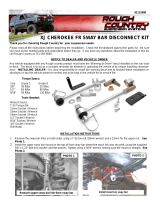
FRONT INSTALLATION INSTRUCTIONS
1. Place vehicle in park and chock the rear wheels. Raise the front of the vehicle with a jack and secure a jack stand
beneath each frame rail behind the front control arms. Ease the frame down onto the stands. Place the jack under
the front axle for support when removing the coil springs.
2. Remove the front tires/wheels, using a 22mm deep well socket.
3. Mark the front driveshaft and pinion, remove from the pinion using a 15mm socket. Hang the front driveshaft, do
not let it rest on the CV boot, damage to the boot can occur.
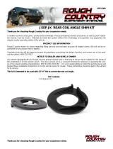
4. Using a 21mm socket and wrench, remove the front track bar from the frame and axle. See Photo 1. Retain hard-
ware for reuse.
5. Using an 18mm socket and wrench remove the bottom sway bar link bolts. Retain hardware for reuse. See Photo 2.
6. Remove the upper and lower shock bolts using a 18mm socket and wrench. You may have to raise the axle with the
jack and pull down on the shock to remove the lower bolt.
See Photo 3. Retain stock hardware.
7. Using a 15mm wrench, remove the brake line bracket from the lower control arm. See Photos 4 & 5. Retain hard-
ware for reuse.
8. Using pliers, remove the wiring harness from the upper control arm. See Photo 6.
9. Loosen the upper control arms using a 18mm wrench.
10. Loosen the lower control arms but do not remove using a 21mm & 24mm wrench.
PHOTO 3 PHOTO 4
PHOTO 5
PHOTO 2 PHOTO 1
PHOTO 6
Remove the track bar bolt. Remove the lower sway link bolt.
Remove the lower shock bolt. Remove the brake line bracket.
Remove the brake line bracket Pull the wiring harness from the control arm.

11. Using pliers, remove the axle vent tube from the differential housing. See Photo 7.
12. Unplug the 4x4 actuator for slack. See Photo 8.
13. Lower the jack, careful not to let the axle reach full droop, and remove the coil spring and spring isolator. See Photo
9.
14. Using a 10mm wrench, remove the brake line bracket from the coil mount. Retain hardware for reuse. See Photo
10.
15. Install the supplied coil spring, making sure the coil spring isolator is in the factory location. See Photo 11.
PHOTO 8 PHOTO 7
PHOTO 9 PHOTO 10
PHOTO 11
Remove the axle vent tube.
Remove the brake line bracket. Remove the coil spring.
Install the coil spring under the coil isolator.
Unplug the 4x4 actuator.

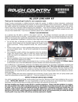
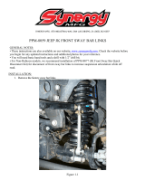
16. Install the bump stop spacer into the lower coil mount. See Photo 12.
17. Place the supplied 3/8” x 3” bolt, washers, and nut (1609BAG7) through the spacer and coil mount. See Photo 13.
18. Tighten using 9/16” wrenches. See Photo 14.
19. Remove the upper shock mounting bolt using a 19mm wrench. Retain hardware for reuse. See Photo 15.
20. If installing V2 or Vertex shocks refer to install instructions included with those shocks. 392 Jeeps skip to
step 22. Install the supplied shock, 660808, in the upper and lower mounts using the factory hardware. Tighten us-
ing a 19mm wrench. Make sure the upper eyelet is offset to the outside of the vehicle. See Photo 16.
21. Tighten the lower shock mounting bolt using an 18mm wrench and socket. Skip to step 25. See Photo 17.
PHOTO 12 PHOTO 13
Tighten using 9/16” wrenches.
PHOTO 14
Install bump stop spacer. Use supplied 3/8” hardware.
PHOTO 16
Install the supplied front shock.
PHOTO 15
Remove the upper shock bolt.
PHOTO 17
Install the shock in the lower mount.

22. Install the supplied shock extension bracket using the supplied 3/8” x 1” bolt, 3/8 washer, and 3/8” flange locknut
(1676BAG), through the bottom hole of the bracket. Do Not Tighten. See Photo 18.
23. Place the supplied crush sleeve (1676BAG) into the factory shock bracket. Install the factory shock hardware into
the brackets and through the sleeve. See Photo 19.
24. Using a jack to compress the suspension, install the shock in the extension bracket using the supplied 12mm x
65mm bolt, 1/2” washers, and 12mm nut (1676BAG). See Photo 20. Tighten the factory bolt using an 18mm socket
and wrench. Torque to 55ft/lbs. Tighten the lower shock bolt using an 18mm socket and wrench. Torque to 55ft/lbs.
PHOTO 18
Install the shock ext. bracket.
PHOTO 20
Install the shock in the lower mount.
Install the supplied front shock.
PHOTO 19

25. Install the brake line bracket on the coil mount using the factory hardware and a 10mm wrench.
26. Remove the brake line bracket from the frame using a 10mm wrench. Retain hardware for reuse. See Photo 21.
27. Install the supplied brake line bracket using the factory bolt for the frame and the supplied 1/4” x 1” bolt, washer, and
nylock nut (66830BAG2). Tighten using a 10mm wrench for the frame bolt. See Photo 22.
28. Remove the sway link from the sway bar using a 6mm Allen and an 18mm wrench. See Photo 23.
29. Install the new supplied offset sway link on sway bar using the supplied 12mm x 65mm bolts, washers, and lock nuts
(65431BAG6). Torque to 55ft/lbs. See Photo 24.
PHOTO 21
Remove the brake line bracket.
PHOTO 22
Install brake line drop bracket.
PHOTO 23
Remove factory sway link.
PHOTO 24
Install supplied bent sway link.

30. Steps 31– 39 should be performed on one side at a time.
31. Loosen the lower control arm axle bolts using 21mm and 24mm wrenches. See Photo 25.
32. Loosen the upper control arm axle bolts using 18mm wrenches. See Photo 26.
33. Remove the upper control arm heat shield bolts using a 10mm wrench. See Photo 27.
34. Remove the upper control arm bolt and flag nut using an 18mm wrench. Retain hardware for reuse. See Photo 28.
35. Remove the lower control arm bolt using 21mm and 24mm wrenches. Retain hardware for reuse. See Photo 29.
36. Install the outer control arm drop bracket (94004230 Dr or 94004231 Pass) into the factory control arm pocket. See
Photo 30.
Loosen lower control arms at axle.
PHOTO 25
Loosen upper control arms at axle.
PHOTO 26
PHOTO 28
PHOTO 27
Remove upper control arm bolt. Remove heat shield.
PHOTO 30
PHOTO 29
Install outer control arm drop bracket. Remove lower control arm bolt.

37. Install the upper 3/4” od sleeve into the upper control arm pocket. See Photo 31.
38. Install the lower 7/8” od sleeve into the lower control arm pocket. See Photo 32.
39. Install the inner control arm drop bracket (94004232 Dr or 94004233 Pass) on the outside of the control arm pockets
using the factory hardware. Do not tighten at this time. See Photo 33.
40. Install the upper control arm in the drop bracket using the supplied 12mm x 80mm bolts, washers, and flange lock
nut (65431BAG4). Do not tighten at this time. See Photo 34.
41. Install the lower control arm in the drop bracket using the supplied 16mm cam bolts, cam washers, and nylock nuts
(65431BAG4). Do not tighten at this time. See Photo 35.
42. Install the brake line bracket on the lower control arm using the factory hardware and a 15mm wrench. See Photo
36.
43. Line up the marks on the driveshaft and the front pinion and attach the driveshaft using the factory hardware and
tighten using a 15mm socket..
Install upper crush sleeve.
PHOTO 31
Install lower crush sleeve.
PHOTO 32
PHOTO 34
PHOTO 33
Install upper control arm. Install inner control arm drop bracket.
PHOTO 36
PHOTO 35
Install brake line bracket. Install lower control arm.

44. Clip the wiring harness into the upper control arm.
45. Attach the axle vent tube to the differential using a pair of pliers.
46. Plug-in the 4x4 actuator. See Photo 37.
47. Attach the sway bar links, to the axle, using the factory hardware and an 18mm socket and wrench. Torque to 55ft/
lbs.
48. Install the front tires/wheels, using a 22mm deep well socket.
49. Lower the vehicle to the floor.
50. Tighten the front upper drop bracket bolt using an 18mm wrench. Torque to factory specs. See Photo 38.
51. Tighten the rear upper drop bracket bolt using a 21mm wrench and 24mm socket. Torque to factory specs. See
Photo 39.
52. Tighten the upper control arm on the axle using 18mm wrenches. Torque to factory specs.
53. Tighten the upper control arm in the drop bracket using an 18mm wrench and socket. Torque to 55ft/lbs. See Pho-
to 40.
54. Tighten the lower control arm at the axle using a 21mm wrench and 24mm socket. Torque to factory specs.
55. Center the cam bolts and tighten using a 24mm wrench and 24mm socket. Torque to 165ft/lbs. See Photo 41.
56. Adjust the front track bar to center the front axle. Make sure the clamps are positioned to maintain clearance
from all obstructions.
57. Torque the track bar mounting bolts to factory specs using a 21mm socket.
58. Tighten the collar pinch bolts using a 17mm wrench and socket. See Photo 42.
Adjust forged track bar.
PHOTO 37
Tighten the upper drop hardware.
PHOTO 38
PHOTO 40
PHOTO 39
Tighten upper control arm. Tighten the lower drop hardware.
PHOTO 41
Plug in the 4x4 actuator.
Tighten lower control arm.
PHOTO 42

REAR INSTALLATION INSTRUCTIONS
1. Jack up the rear of the vehicle and support the vehicle with jack stands, so that the rear wheels are off the ground.
Chock front wheels. Position a jack so it supports, but does not raise the rear axle.
2. Remove the rear tires/wheels, using a 22mm deep well socket.
3. Using a 21mm socket remove the track bar bolt at the axle. Retain the stock hardware for reuse. See Photo 1.
4. Using an 18mm socket and wrench, remove the lower shock mounting hardware. Save for reuse. See Photo 2.
5. Using an 8mm socket, remove the 3 bolts holding the lower fender liner, remove the liner. Retain hardware for re-
use. See Photo 3.
6. 392 Jeeps skip to next step. Using an 18mm socket, remove the upper shock bolt and remove the shock. See
Photo 4.
7. Using an 18mm socket and wrench, remove the lower sway bar link hardware. See Photo 5.
8. Lower the axle and remove the coil spring and coil spring isolator. See Photo 6.
PHOTO 2
PHOTO 3 PHOTO 4
PHOTO 1
Remove the rear track bar bolt.
Remove the upper shock bolt.
Remove the lower fender liner.
Remove the lower shock bolt.
PHOTO 6
PHOTO 5
Remove the lower sway link bolt. Remove the coil spring and isolator.

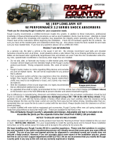
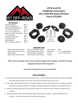
9. Place the supplied track bar relocation bracket over the factory track bar bracket, using the supplied 14mm x 80mm
bolt washers, nut and supplied sleeve (65431BAG6). Tighten using a 21mm socket. Make sure the track bar relo-
cation bracket tab is against the edge of the factory bracket. See Photo 7.
10. Use the supplied bracket as a drill guide. See Photos 8 & 9.
NOTE: For a non 392 model drill the top hole from Photo 9 but for a 392 model, drill the bottom hole.
11. Drill the 3 holes from Photos 8 & 9 using a 15/32” drill. See Photo 10.
12. Secure the supplied bracket to the factory bracket using the supplied 7/16” x 1.25” bolts, washers, and nylock nuts
(65431BAG6). See Photo 11.
13. Torque to 60ft/lbs using a 5/8” socket and wrench. See Photo 12.
PHOTO 10
PHOTO 7 PHOTO 8
PHOTO 9
Drill using a 15/32” drill. Drill using a 15/32” drill.
Mark for drilling.
Install the track bar relocation bracket.
PHOTO 12
PHOTO 11
Install 7/16” hardware. Tighten 7/16” hardware.
Non 392 Model
392 Model

14. Torque to 60ft/lbs using a 5/8” socket and wrench. See Photo 13.
15. Install the supplied bump stop spacer on the axle using the supplied (1609BAG6) 3/8” x .75” bolts, washers, and
flange lock nuts. (You will use 2 bolts, 2 washers, and 2 nuts per side). Using a 9/16” wrench and socket, torque
the hardware to 30ft/lbs. See Photos 14& 15.
16. Using a 6mm Allen and an 18mm wrench remove the sway link from the sway bar. See Photo 16.
17. Using a 15mm socket, remove the factory sway bar from the frame. See Photo 17.
18. Flip the sway bar from passenger side to driver side.
19. Install the sway bar drop brackets between the sway bar and the frame, using the supplied 10mm x 55mm bolts, lock
washers, and flat washers (65431BAG6). Torque to 32ft/lbs using a 16mm socket. See Photo 18.
PHOTO 17
Remove sway bar.
Tighten bump stop spacer hardware.
PHOTO 15
PHOTO 14
Install the bump stop spacer.
PHOTO 13
Tighten 7/16” hardware.
PHOTO 18
Install the sway bar drop spacer.
PHOTO 16
Remove the sway link.
/