Arduino ATmega328 User manual

Type
User manual

Arduino ATmega328: a microcontroller board based on the ATmega328, designed for building electronic projects. With 14 digital I/O pins, 6 analog inputs, a USB connection, and more, it's perfect for interfacing with various sensors, actuators, and displays. Create interactive projects, automate tasks, and explore the world of electronics with ease.

Arduino ATmega328: a microcontroller board based on the ATmega328, designed for building electronic projects. With 14 digital I/O pins, 6 analog inputs, a USB connection, and more, it's perfect for interfacing with various sensors, actuators, and displays. Create interactive projects, automate tasks, and explore the world of electronics with ease.

Arduino Uno
Overview
The Arduino Uno is a microcontroller board based on the ATmega328 (datasheet). It has 14 digital
input/output pins (of which 6 can be used as PWM outputs), 6 analog inputs, a 16 MHz crystal oscillator, a
USB connection, a power jack, an ICSP header, and a reset button. It contains everything needed to
support the microcontroller; simply connect it to a computer with a USB cable or power it with a AC-to-DC
adapter or battery to get started.
The Uno differs from all preceding boards in that it does not use the FTDI USB-to-serial driver chip.
Instead, it features the Atmega8U2 programmed as a USB-to-serial converter.
"Uno" means one in Italian and is named to mark the upcoming release of Arduino 1.0. The Uno and
version 1.0 will be the reference versions of Arduno, moving forward. The Uno is the latest in a series of
USB Arduino boards, and the reference model for the Arduino platform; for a comparison with previous
versions, see the index of Arduino boards.
Summary
Microcontroller ATmega328
Operating Voltage 5V
Input Voltage (recommended) 7-12V
Input Voltage (limits) 6-20V
Digital I/O Pins 14 (of which 6 provide PWM output)
Analog Input Pins 6
DC Current per I/O Pin 40 mA
DC Current for 3.3V Pin 50 mA
Flash Memory 32 KB (ATmega328) of which 0.5 KB used by bootloader
SRAM 2 KB (ATmega328)
EEPROM 1 KB (ATmega328)
Clock Speed 16 MHz
Schematic & Reference Design
EAGLE files: arduino-uno-reference-design.zip
Schematic: arduino-uno-schematic.pdf
Power
The Arduino Uno can be powered via the USB connection or with an external power supply. The power
source is selected automatically.
External (non-USB) power can come either from an AC-to-DC adapter (wall-wart) or battery. The adapter
can be connected by plugging a 2.1mm center-positive plug into the board's power jack. Leads from a
battery can be inserted in the Gnd and Vin pin headers of the POWER connector.
The board can operate on an external supply of 6 to 20 volts. If supplied with less than 7V, however, the
5V pin may supply less than five volts and the board may be unstable. If using more than 12V, the voltage
regulator may overheat and damage the board. The recommended range is 7 to 12 volts.
The power pins are as follows:
VIN. The input voltage to the Arduino board when it's using an external power source (as opposed to
5 volts from the USB connection or other regulated power source). You can supply voltage through
this pin, or, if supplying voltage via the power jack, access it through this pin.
5V. The regulated power supply used to power the microcontroller and other components on the
board. This can come either from VIN via an on-board regulator, or be supplied by USB or another
regulated 5V supply.
3V3. A 3.3 volt supply generated by the on-board regulator. Maximum current draw is 50 mA.
GND. Ground pins.
Memory
The ATmega328 has 32 KB (with 0.5 KB used for the bootloader). It also has 2 KB of SRAM and 1 KB of
EEPROM (which can be read and written with the EEPROM library).
Input and Output
Each of the 14 digital pins on the Uno can be used as an input or output, using pinMode(), digitalWrite(),
and digitalRead() functions. They operate at 5 volts. Each pin can provide or receive a maximum of 40 mA
and has an internal pull-up resistor (disconnected by default) of 20-50 kOhms. In addition, some pins have
specialized functions:
Serial: 0 (RX) and 1 (TX). Used to receive (RX) and transmit (TX) TTL serial data. These pins are
connected to the corresponding pins of the ATmega8U2 USB-to-TTL Serial chip.
External Interrupts: 2 and 3. These pins can be configured to trigger an interrupt on a low value,
a rising or falling edge, or a change in value. See the attachInterrupt() function for details.
PWM: 3, 5, 6, 9, 10, and 11. Provide 8-bit PWM output with the analogWrite() function.
SPI: 10 (SS), 11 (MOSI), 12 (MISO), 13 (SCK). These pins support SPI communication using
the SPI library.
LED: 13. There is a built-in LED connected to digital pin 13. When the pin is HIGH value, the LED is
on, when the pin is LOW, it's off.
The Uno has 6 analog inputs, labeled A0 through A5, each of which provide 10 bits of resolution (i.e. 1024
different values). By default they measure from ground to 5 volts, though is it possible to change the upper
end of their range using the AREF pin and the analogReference() function. Additionally, some pins have
specialized functionality:
I2C: 4 (SDA) and 5 (SCL). Support I2C (TWI) communication using the Wire library.
There are a couple of other pins on the board:
AREF. Reference voltage for the analog inputs. Used with analogReference().
Reset. Bring this line LOW to reset the microcontroller. Typically used to add a reset button to
shields which block the one on the board.
See also the mapping between Arduino pins and ATmega328 ports?.
Communication
The Arduino UNo has a number of facilities for communicating with a computer, another Arduino, or other
microcontrollers. The ATmega328 provides UART TTL (5V) serial communication, which is available on
digital pins 0 (RX) and 1 (TX). An ATmega8U2 on the board channels this serial communication over USB
and appears as a virtual com port to software on the computer. The '8U2 firmware uses the standard USB
COM drivers, and no external driver is needed. However, on Windows, a .inf file is required. The Arduino
software includes a serial monitor which allows simple textual data to be sent to and from the Arduino
board. The RX and TX LEDs on the board will flash when data is being transmitted via the USB-to-serial
chip and USB connection to the computer (but not for serial communication on pins 0 and 1).
A SoftwareSerial library allows for serial communication on any of the Uno's digital pins.
The ATmega328 also supports I2C (TWI) and SPI communication. The Arduino software includes a Wire
library to simplify use of the I2C bus; see the documentation for details. For SPI communication, use the
SPI library.
Programming
The Arduino Uno can be programmed with the Arduino software (download). Select "Arduino Uno from the
Tools > Board menu (according to the microcontroller on your board). For details, see the reference and
tutorials.
The ATmega328 on the Arduino Uno comes preburned with a bootloader that allows you to upload new
code to it without the use of an external hardware programmer. It communicates using the original STK500
protocol (reference, C header files).
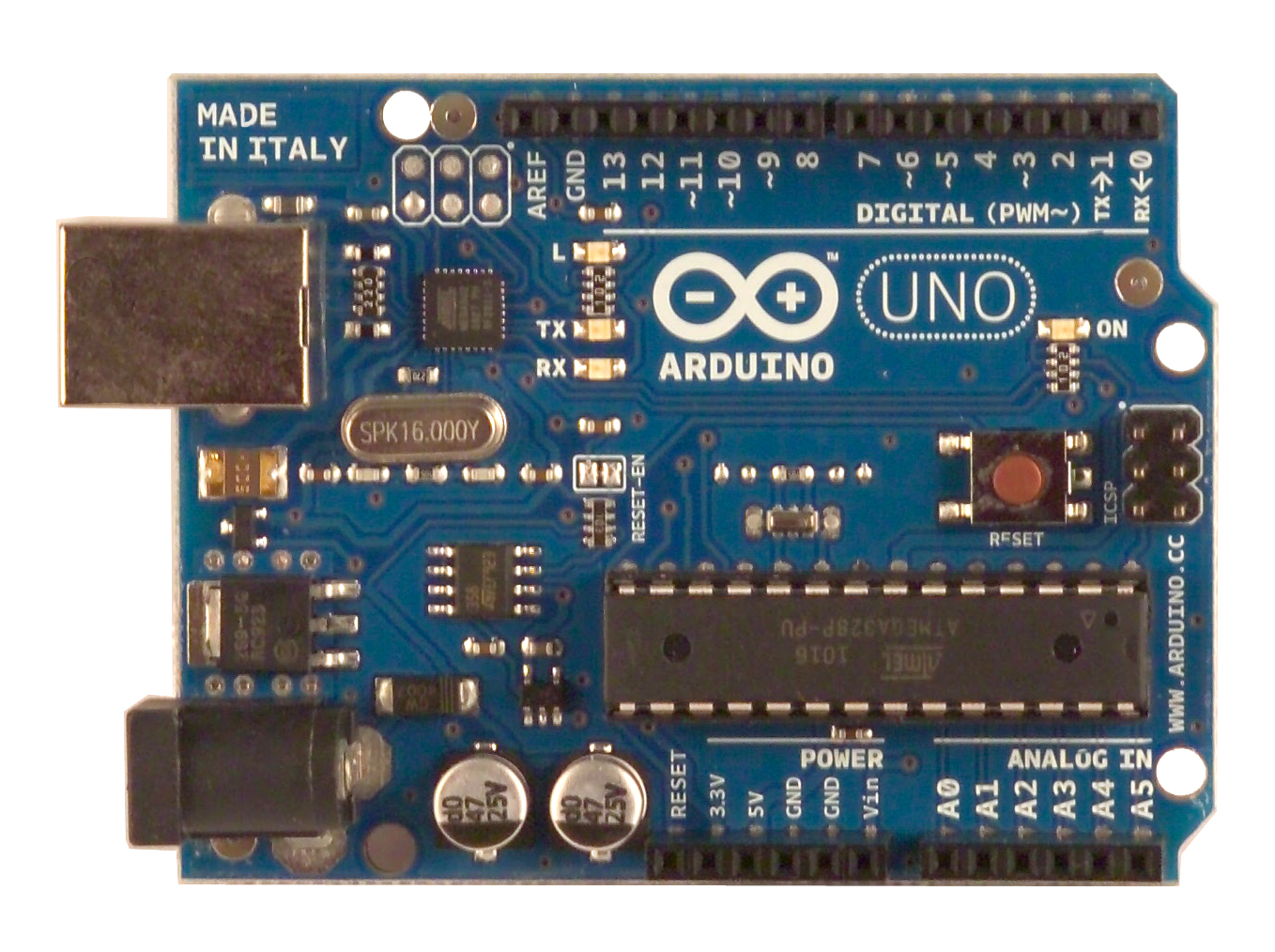
You can also bypass the bootloader and program the microcontroller through the ICSP (In-Circuit Serial
Programming) header; see these instructions for details.
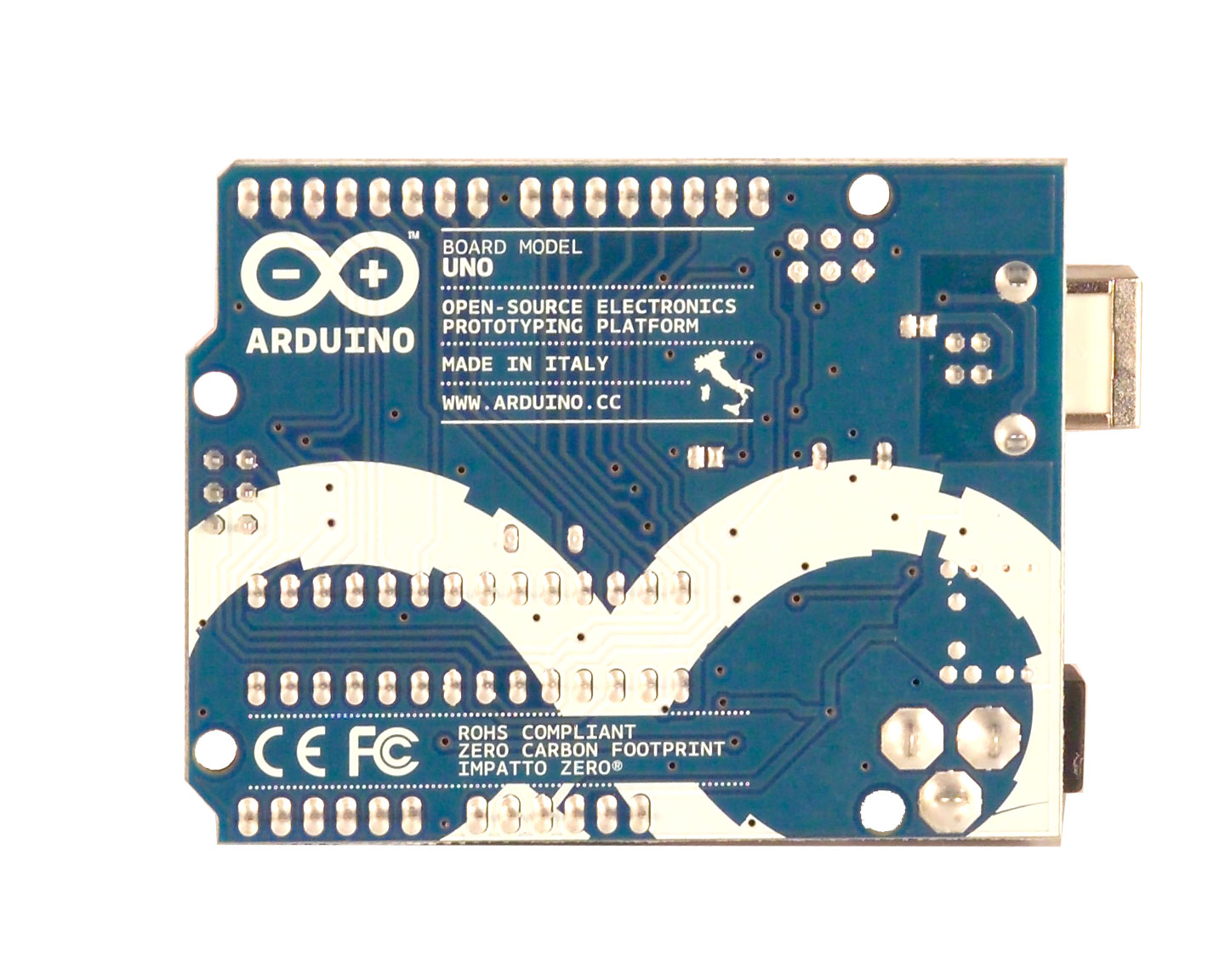
The ATmega8U2 firmware source code is available . The ATmega8U2 is loaded with a DFU bootloader,
which can be activated by connecting the solder jumper on the back of the board (near the map of Italy)
and then resetting the 8U2. You can then use Atmel's FLIP software (Windows) or the DFU programmer
(Mac OS X and Linux) to load a new firmware. Or you can use the ISP header with an external programmer
(overwriting the DFU bootloader). See this user-contributed tutorial for more information.
Automatic (Software) Reset
Rather than requiring a physical press of the reset button before an upload, the Arduino Uno is designed in
a way that allows it to be reset by software running on a connected computer. One of the hardware flow
control lines (DTR) of the ATmega8U2 is connected to the reset line of the ATmega328 via a 100 nanofarad
capacitor. When this line is asserted (taken low), the reset line drops long enough to reset the chip. The
Arduino software uses this capability to allow you to upload code by simply pressing the upload button in
the Arduino environment. This means that the bootloader can have a shorter timeout, as the lowering of
DTR can be well-coordinated with the start of the upload.
This setup has other implications. When the Uno is connected to either a computer running Mac OS X or
Linux, it resets each time a connection is made to it from software (via USB). For the following half-second
or so, the bootloader is running on the Uno. While it is programmed to ignore malformed data (i.e. anything
besides an upload of new code), it will intercept the first few bytes of data sent to the board after a
connection is opened. If a sketch running on the board receives one-time configuration or other data when
it first starts, make sure that the software with which it communicates waits a second after opening the
connection and before sending this data.
The Uno contains a trace that can be cut to disable the auto-reset. The pads on either side of the trace can
be soldered together to re-enable it. It's labeled "RESET-EN". You may also be able to disable the auto-
reset by connecting a 110 ohm resistor from 5V to the reset line; see this forum thread for details.
USB Overcurrent Protection
The Arduino Uno has a resettable polyfuse that protects your computer's USB ports from shorts and
overcurrent. Although most computers provide their own internal protection, the fuse provides an extra
layer of protection. If more than 500 mA is applied to the USB port, the fuse will automatically break the
connection until the short or overload is removed.
Physical Characteristics
The maximum length and width of the Uno PCB are 2.7 and 2.1 inches respectively, with the USB connector
and power jack extending beyond the former dimension. Four screw holes allow the board to be attached
to a surface or case. Note that the distance between digital pins 7 and 8 is 160 mil (0.16"), not an even
multiple of the 100 mil spacing of the other pins.
ATMEGA8
ICSP
+5V
GND
+5V
+5V
GND
GND
GND
+5V
GND
100n
GND
47u 47u
GND GND
GND
GND
GREEN
GND
+5V
YELLOW
YELLOW
M7
GND
MC33269D-5.0
MC33269ST-5.0T3
100n
GND
500mA
+5V
+5V
100n
GND
YELLOW
GND
FDN304V
+5V
LM358D LM358D
GNDGND
+5V
100n
+5V
ATMEGA8U2-MU
GND
100n
ICSP
+5V
GND
GND
16MHz
16MHz
GND
PGB1010604
PGB1010604
BLM21
1M
1K
1K
1K
1K
GND
10K
10K
10K
10K
100n
1u
1K
1K
1K
1K
22R
22R
22R
22R
1u
1M
16MHz
16MHz
TS42
22p22p
22p22p
GND
GND
GND
27R
(ADC5)PC5 28
(ADC4)PC4 27
(ADC3)PC3 26
(ADC2)PC2 25
(ADC1)PC1 24
(ADC0)PC0) 23
(SCK)PB5 19
(MISO)PB4 18
(MOSI)PB3 17
(SS)PB2 16
(OC1)PB1 15
(ICP)PB0 14
(AIN1)PD7 13
(AIN0)PD6 12
(T1)PD5 11
(T0)PD4 6
(INT1)PD3 5
(INT0)PD2 4
(TXD)PD1 3
(RXD)PD0 2
GND
8VCC
7
AVCC
20 AREF
21
XTAL1
9
XTAL2
10
RESET
1
AGND
22
ZIC1
1 2
3 4
5 6
ICSP
1
2
3
4
5
6
7
8
IOL
1
2
3
4
5
6
7
8
IOH
1
2
3
4
5
6
AD
C2PC1 PC2
ON
RX
TX
D1
1
1
2
2
33
1
2
3
4
P$1
P$1 P$2
P$2
X2
VI
3
1
VO 2
IC2
ADJ
1
IN
3OUT 4
2
IC1
1
2
3
4
5
6
POWER
C4
F1
C7
L
T1
2
3
1
U1A
6
5
7
U1B
84
C1
(PCINT9/OC1B)PC5 25
(PCINT10)PC4 26
(INT4/ICP1/CLK0)PC7 22
(OC1A/PCINT8)PC6 23
(AIN2/PCINT11)PC2 5
(PCINT5)PB5 19
(T1/PCINT4)PB4 18
(PD0/MISO/PCINT3)PB3 17
(PDI/MOSI/PCINT2)PB2 16
(SCLK/PCINT1)PB1 15
(SS/PCINT0)PB0 14
(CTS/HWB/AIN6/TO/INT7)PD7 13
(RTS/AIN5/INT6)PD6 12
(XCK/AIN4/PCINT12)PD5 11
(INT5/AIN3)PD4 10
(TXD1/INT3)PD3 9
(RXD1/AIN1/INT2)PD2 8
(AIN0/INT1)PD1 7
(OC0B/INT0)PD0 6
GND
3VCC
4
AVCC
32
UVCC
31
XTAL1
1
XTAL2(PC0)
2
RESET(PC1/DW)
24
UGND
28
U3
PAD
EXP
UCAP
27
D-
30
D+
29
(PCINT6)PB6 20
(PCINT7/OC0A/OC1C)PB7 21
C5
1 2
3 4
5 6
ICSP1
Y2
Y1
21 UBOOT
Z1
Z2
2 1
GROUND
L1
21 RESET-EN
R2
18 RN2A
27 RN2B
36 RN2C
45 RN2D
18 RN1A 2 7
RN1B
36 RN1C
4 5
RN1D
C6
C8
18 RN4A
27 RN4B
3 6
RN4C
4 5
RN4D
18 RN3A
2 7
RN3B
3 6
RN3C
45 RN3D
C3
R1
21
Q1
21
Q2
1 3
42
RESET
5
C10C12
C9C11
IN
1
EN
3
NC/FB 4
OUT 5
GND
2
R3
+5V
+5V
GND
AREF
AREF
RESET
RESET
VIN
VIN
VIN
M8RXD
M8RXD
M8TXD
M8TXD
SCK
PWRIN
D-
D+
+3V3
+3V3
+3V3
MISO
MOSI
SS
SS
DTR
GATE_CMD
CMP
USBVCC
USBVCC
USBVCC
XTAL2
XTAL2
XTAL1
XTAL1
VUCAP
RD-
RD-
RD+
RD+
RESET2
MISO2
MOSI2
SCK2
USHIELD
UGND
UGND
XUSB
XT2
XT2
XT1
XT1
RXLED
TXLED
AD0
AD1
AD2
AD3
AD4
AD5
IO2
IO1
IO0
IO3
IO4
IO5
IO6
IO7
IO8
IO9XT1R
+
+
USB
0
1
2
3
4
5
6
7
8
9
10
11
12
13
Arduino UNO Reference Design
USB boot En
TM
Reference Designs ARE PROVIDED "AS IS" AND "WITH ALL FAULTS". Arduino DISCLAIMS ALL OTHER WARRANTIES, EXPRESS OR IMPLIED,
Arduino may make changes to specifications and product descriptions at any time, without notice. The Customer must not
REGARDING PRODUCTS, INCLUDING BUT NOT LIMITED TO, ANY IMPLIED WARRANTIES OF MERCHANTABILITY OR FITNESS FOR A PARTICULAR PURPOSE
rely on the absence or characteristics of any features or instructions marked "reserved" or "undefined." Arduino reserves
these for future definition and shall have no responsibility whatsoever for conflicts or incompatibilities arising from future changes to them.
The product information on the Web Site or Materials is subject to change without notice. Do not finalize a design with this information.
  • Page 1 1
  • Page 2 2
  • Page 3 3
  • Page 4 4
  • Page 5 5
  • Page 6 6

Arduino ATmega328 User manual

Type
User manual

Arduino ATmega328: a microcontroller board based on the ATmega328, designed for building electronic projects. With 14 digital I/O pins, 6 analog inputs, a USB connection, and more, it's perfect for interfacing with various sensors, actuators, and displays. Create interactive projects, automate tasks, and explore the world of electronics with ease.

Ask a question and I''ll find the answer in the document

Finding information in a document is now easier with AI