Page is loading ...


CONTENTS
Product Features and Specifications .................................................3
Installation Requirement ................................................................5
Steps of Installation ......................................................................6
Exploded View ............................................................................32
Test Run ................................................................................... 35
Operation Instruction ..................................................................37
Maintenance ..............................................................................37
Trouble Shooting ........................................................................38
Parts List ..................................................................................39

- 3 -
I. PRODUCT FEATURES AND SPECIFICATIONS
CLEAR-FLOOR DIRECT-DRIVED MODEL FEATURES
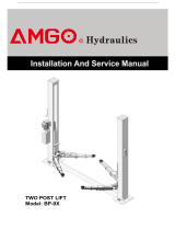
Model PV-15P (See Fig. 1)
· Direct-drive design, minimizes the lift wear parts and breakdown ratio
· Dual hydraulic cylinders, designed and made on ANSI standards, utilizing NOK oil seal
in the cylinders
· Self- lubricating UHMW Polyethylene sliders and bronze bushings
· Single-point safety release with dual safety design
. Clear-floor design, provides unobstructed floor use
. Overhead safety shut-off device prevents vehicle damage
. Standard adjustable heights accommodates different ceiling heights
MODEL PV-15 SPECIFICATIONS
Model Style Lifting
Capacity Lifting
Time Lifting Height
Overall Height Overall
Width
Width
Between
columns
Minimum
Pad Height
for
stackable
adapter
Motor
PV-15P Clear-floor
Direct-drive
6.8 T
15,000lbs 72S 1872-2142mm
73 3/4”–84 3 /8”
3812/4192/4497mm
150”/165”/177”
3829mm
150 3/4”
3137mm
123 1/2”
145
5 3/4” 4.0HP
Fig. 1

- 4 -
Arm Swings View For Model PV-15P
Fig. 2
63 ¼
”
41 1/8”
63 ¼”
41 1/8”
150 ¾
”
109 ¾”

- 5 -
II. INSTALLATION REQUIREMENT
A. TOOLS REQUIRED
Rotary Hammer Drill (19mm / ¾”) Carpenter’s Chalk
Hammer Screw Sets
Level Tape Measure (25ft)
Crescent Wrench (12") Pliers
Wrench set:(10#、13#、14#、15#、17# Lock Wrench
19#、24#、27#、30#)
Ratchet Spanner With Socket (28mm)
Fig.3
Socket Head Wrench (3#, 5#, 8#)

- 6 -
B. CONCRETE SPECIFICATIONS (See Fig. 4)
Concrete specifications must be adhered to the following specification.
Failure to do so may result in lift and/or vehicle falling.
1. Concrete must be thickness 6 inches minimum and without reinforcing steel bars, and
must be totally dry before lift installation.
2. Concrete must be in good condition and must have a test strength 3,500psi
(250kg/cm²) minimum.
3. Floors must be level with no cracks or holes.
C. POWER SUPPLY
The electrical source must be 3HP minimum. The source cable size must be 2.5mm² and
in good condition of contacting with floor.
III. INSTALLATION STEPS
A. Location of installation
Check the installation location (concrete, layout, space size etc.) is suitable for lift
installation.
B. Use a carpenter’s chalk line to establish installation layout of the base plate (See Fig. 5)
Model PV-15P
Fig.4
Fig. 5
150 ¾”
Chalk Line

- 7 -
C. Check the parts before assembly.
1. Packaged lift, hydraulic power unit and parts box (See Fig. 6).
2. Move the lift aside with a fork lift or hoist, and open the outer packing carefully
(See Fig. 7).
3. Remove aside the top connecting assembly. (See Fig. 8).
Shipment Parts list
Fig. 6
Fig. 7
Fig. 8
Top Connecting
Assembly
Serial No.

- 8 -
4. Lift the upper column with a fork lift or hoist, loosen the bolts on the upper package
stand, take off the upper outer column, then take out the parts in the inner column (See
Fig. 9).
5. Lift the lower column with a fork lift or hoist, take down the package stand, then take off
the lower outer column, take out the parts in the inner column (See Fig. 10).
6. Move aside the parts and check the parts according to the shipment parts list
(See Fig. 11).
Fig. 9
Fig. 10
Fig. 11

- 9 -
7. Open the carton of parts and check the parts according to parts box list (See Fig. 12).
8. Check the parts in the part bag #1 according to parts bag list (See Fig. 13).
9. Check the parts in the parts bag #2 according to parts bag list (See Fig. 14).
Fig. 14
Fig. 12
Fig. 13

- 10 -
D. Install parts on the extension columns (See Fig. 15).
Fig. 15

- 11 -
E. Install hydraulic cylinders
Connect the extended straight fitting and 90° fitting, and then install the cylinder
inside the carriages (See Fig. 16).
Fig. 16
Power side column
Of
f
side column
The direction of fitting

- 12 -
F. Install columns
Lay down the two columns on the installation site parallel, position the power side column
according to the actual installation site. Usually, it is suggested to install power side column
on the front-right side from which vehicles are driven to the lift. This lift is designed with
2-Section columns. Adjust the height according to the ceiling height and connect the inner
and outer columns.
1. When the ceiling height is over 4500mm (177 1/8”), connect the outer columns with the
lower hole (See Fig. 17).
Fig. 17 High setting

- 13 -
2. When the ceiling height is between 4200mm (165 3/8”) to 4500mm (177 1/8”), connect
the outer columns with the middle hole (See Fig.18).
Fig. 18 Low setting

- 14 -
3. When the ceiling height is less than 4200mm (165 3/8”), connect the outer columns with
the upper hole. For this height setting you will need to purchase the shorter cables
(part#217063) (See Fig.19).
Fig. 19 Special low setting

- 15 -
G. Position columns (Do not drill anchor holes at this time)
Position the power side column in its designated place. Place the off side column
approximately 12 1/2” from the power side column. Install the overhead top beam. Once
the overhead top beam is in place and secured, the anchor holes can be drilled. (See
Fig.20 & 21).
Fig. 20
Width between columns: 123 1/2”
Overall width:150 3/4"
Adjusting with
the shims
37
Drilling Cleaning Bolting

- 16 -
H. Install overhead top beam
1. With help of the hook on the top beam, put one side of the top beam on top of the extension
column and connect the top beam to the extension column with bolts, tighten the bolts.
Then assemble the connecting bracket (See Fig. 21).
Fig.
21
Hook on to the
extension columns
Tighten the bolts

- 17 -
2. Assemble overhead top beam, tighten the columns anchor bolts (See Fig. 22).
Tighten
Fig. 22

- 18 -
I. Installing the limit switch control bar and limit switch (See Fig. 23).
Fig.
23
NC: Normal contact
65
Loosen Screw on the
Drive Rod for
adjustment, Tighten the
screw after adjustment
Adjust Drive Rod on
Limit Switch
Limit Switch connected
with cable
Fig. 23

- 19 -
J. Install safety device (See Fig. 24 & Fig. 25).
Fig. 24 Power side safety device
Fig. 25 Off side safety device

- 20 -
K. Lift the carriages up by hand and lock them at the same level (See Fig. 26).
Fig. 26
/