Page is loading ...

SG100 (NZ701) Texmate, Inc. Tel. (760) 598-9899 1
www.texmate.com
Digital Display: 14-segment alphanumeric, 0.56” (14.2 mm) LEDs.
Display Color: Red (standard). Call Texmate for other options.
Display Range: -199999 to 999999.
Display Update Rate: 3, 10, or 100 times per second.
Display Dimming: 8 brightness levels. Front panel selectable.
Scrolling Display Text Messaging: Full alphanumeric text charac-
ters supported.
Polarity: Assumed positive. Displays – negative.
Annunciators: 6 red LEDs on front panel; one per setpoint.
Overrange Indication:
Underrange Indication:
Front Panel Controls: PROGRAM, UP and DOWN buttons.
Excitation: 5 V DC, 130 mA maximum, eight x 350 Ω bridges.
Input Range: Software selectable for sensors from 1 mV/V to 20
mV/V.
Zero Drift: ± 40 nV/ °C typical.
Span Drift: ± 5 ppm/ ° C of full scale maximum.
Non-linearity: ± 0.003% of full scale maximum.
Input Noise: 160 nVpp typical at 1 Hz output rate.
Signal processing Rate: 50 Hz maximum, 1 Hz minimum.
Warm Up Time: Up to 10 minutes for load cell to settle.
Conversion Rate: 1, 10, 50 Hz selectable.
Control Output Rate: Can be selected for 100 msec or 10 msec.
Frequency Select: 50 Hz/60 Hz noise rejection, software selectable.
Load Cell Input: 4 or 6-wire Bridge, header selectable.
Output:
Two Form C Relay Specifications: 9 A 240 VAC~1/2 HP, 8
A 24 VDC. Isolation 3000 V. UL listed.
Optional Four Form A Relay Specifications: 4 A 240 VAC,
4 A 24 VDC. Isolation 3000 V. UL listed.
Environmental
Operating Temperature: 0 to 50 ˚C (32 ˚F to 122 ˚F).
Storage Temperature: -20 ˚C to 70 ˚C (-4 ˚F to 158 ˚F).
Relative Humidity: 95% (non-condensing) at 40 ˚C (104 ˚F).
Mechanical
Case Dimensions: 1/8 DIN, 96x48 mm (3.78” x 1.89”)
Case Material: 94V-0 UL rated self-extinguishing polycarbonate.
Weight: 11.5 oz (0.79 lbs), 14 oz (0.96 lbs) when packed.
Approvals
CE: As per EN-61000-3/4/6 and EN-61010-1.
UL Listed
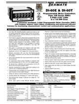
SG100
Weighing Controller
USER MANUAL
Introduction Specifications
• 1/8DINCase
• 6-digit,0.56”(14.2mm)
Alphanumeric Display
• 3-buttonFrontPanelOperation
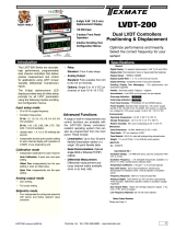
The SG100 weighing controller is a high performance, programmable digital
weighing system delivering precise measurement and control from a load cell
input. It is pre-configured with the calibration options required for silo and tank
weighing applications.
The 6-digit alphanumeric LED display provides easy to follow setup prompts
for all load cell parameters using intuitive scrolling text menus, including:
• IntuitiveScrollingTextMenu
Configuration
• StatusInputs.Manual zero, tare
and reset tare from external status
inputs.
• Relays.Two 9A Form C standard,
Optional Four 4A Form A.
• Setpoints.Four programmable set-
points with advanced multiple timer
modes, hysteresis, deviation, PID,
and setpoint tracking.
• AnalogOutput.Fully scalable from
4 to 20 mA (or reverse) as stan-
dard, or optional 0 to 10 V DC and
Dual 4-20mA/0-1V DC.
• Totalizers.Dual totalizers with inde-
pendent reset and scaling.
• Linearization.Up to four 32-point
flexible linearization tables or a sin-
gle 125-point flexible table.
The resident Tiger 320 operating system also provides a range of built-in
measurement and control functions providing a reliable and precise industrial
quality weighing solution. These include:
• Manual Trim for Zero Offset and Span.
• Manual mV/V Setup.
• Zero Span Calibration.
• Decimal Point Position.
• Last Digit rounding.
• Windowed Signal Averaging.
• Selectable Sampling Rate.
• Auto Zero Maintenance.
• Manual Zero.
• Tare and Reset Tare.
• SerialCommunications.
RS-485 Standard.
• DataLogging.Optional data
logging of up to 4000 samples
with real-time clock.
• Excitation.The controller pro-
vides excitation for up to eight
4 or 6-wire 350 Ω load cells.
• PowerSupplies.
Standard high voltage
AC / DC power supply 85-265
V AC / 95-300 V DC.
Optional low voltage
AC / DC power supply 15-48 V
AC / 15-72 V DC.
Prog.
S
P1SP2 S
P4
SP3 SP5SP
6
Packaging &
Check Weighing
Batching &
Filling
Vehicle
Weighing
Silo & Tank
Weighing
E469078

Texmate, Inc. Tel. (760) 598-9899
2SG100 (NZ701)
www.texmate.com
P
4 Secs
Input Setup
Start
Prog.
SP1 SP2SP4SP3SP5 SP6
Prog.
SP1 SP2 SP4SP3SP5 SP6
P
Prog.
SP1 SP2 SP4SP3 SP5 SP6
P
Input Calibration
Prog.
SP1SP2 SP4SP3SP5 SP6
P
P
Zero Maintenance
P
Averaging Parameters
P
Analog Output Scaling
Prog.
SP1SP2 SP4SP3SP5 SP6
Prog.
SP1SP2 SP4SP3 SP5 SP6
P
Prog.
SP1 SP2 SP4SP3 SP5 SP6
Prog.
SP1 SP2SP4SP3 SP5 SP6
P
Prog.
SP1SP2 SP4SP3 SP5 SP6
Prog.
SP1 SP2 SP4SP3 SP5 SP6
P
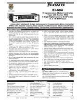
Takes you into the Input Setup mode and provides selection for:
• Supply Frequency: 50 or 60 Hz.
• Sampling Rate: 1, 10, or 50 Hz (averaged over 800 samples).
• Select for: 1, 2, 3, or 20 mV/V sensors.
• Decimal Point Position.
• Last Digit Rounding.
Takes you into the Input Calibration mode and provides selection for:
• More than 100,000 counts of resolution.
• 2-point auto calibration for zero and span.
• Manual sensor span calibration.
• Manual sensor mV/V calibration.
• Manual zeroing.
• Manual trim for zero offset.
• Manual trim for span.
Takes you into the Zero Maintenance mode and provides selection for:
• Auto zero maintenance: capture band, rate of change, and aperture window.
• Manual zero with aperture window limit.
Takes you into the Averaging Parameters mode and provides:
A menu that allows you to select the number of input samples to be averaged
within an adjustable window for smooth and fast response.
Takes you into the Analog Output Scaling mode and provides:
A menu that allows you to set zero and full scale analog output calibration
settings.
See Page 3
See Page 4
See Page 5
See Page 7
See Page 8
Table of Contents
Specifications ...........................................1
Introduction.............................................1
Intuitive Scrolling Text Menus...............................2
Further Programming .....................................2
Advanced Functions......................................2
Configuration Menus Logic Tree ............................2
Input Setup .............................................3
Input Calibration .........................................4
Zero Maintenance .......................................5
Averaging Parameters ....................................7
Analog Output Scaling . . . . . . . . . . . . . . . . . . . . . . . . . . . . . . . . . . . . 8
Load Cell Controller – Programming Logic Tree ................9
Code Blanking & Macro Checking Procedure .................10
Input Signal Setup Procedures ............................11
Analog Output Procedures................................12
Connector Pinouts ......................................15
Installation ............................................17
Installation Guideline ....................................18
Advanced Functions and Options ..........................19
Application Examples ....................................19
Ordering Information ....................................20
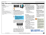
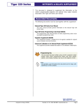
Configuration Menus Logic Tree
Advanced Functions
After the controller has been powered up, the display settles
and indicates the input signal calibrated value. This is known
as the operational mode and is generally referred to as the
operational display throughout this document.
Intuitive scrolling text menus provide quick access to a range
of configuration modes for easy load cell application setup. The
Load Cell Controller – Setup Menu Logic Tree below describes
all the modes with intuitive scrolling text menus.
Prog.
SP1 SP2SP4SP3SP5 SP6
OPERATIONAL DISPLAY
Press the but-
ton for 4 sec-
onds to enter the
Configuration
Menus.
Press the and buttons at the same time
to enter the Brightness Mode and set
the brightness setting.
Press the button again to enter the
Calibration Mode and configure the
following settings:
• Calibrate analog output’s milliamp or voltage
output.
• Configure serial port settings if serial board
installed.
Scrolling Menus
OtherCalibrationSettings
Press the and buttons at the same time
to enter the Setpoint Programming
Mode
Setpoint Programming Mode
Further programming of controller functions include calibrating
the analog output’s milliamp/voltage output, serial port settings,
and setpoint programming modes.
Further Programming
Intuitive Scrolling Text Menus
Additional built-in measurement and control functions are also
available with the SG100 controller’s resident Tiger 320 oper-
ating system. These can be programmed from the front panel
buttons or via Texmate’s configuration utility program, which is
available for free download at: www.texmate.com.

SG100 (NZ701) Texmate, Inc. Tel. (760) 598-9899 3
www.texmate.com
Prog.
SP1 SP2SP4SP3SP5 SP6
P
4 Secs
[_ _INPUT
SETUP]
Prog.
SP1SP2 SP4SP3SP5 SP6
P
[_ _SELECT SUPPLY
REJECTION]
Prog.
SP1SP2 SP4SP3SP5 SP6
Prog.
SP1SP2 SP4SP3SP5 SP6
P
[_ _SELECT SAMPLING
RATE]
Prog.
SP1SP2 SP4SP3SP5 SP6
YES YES
Prog.
SP1 SP2SP4SP3SP5 SP6
Prog.
SP1 SP2SP4SP3SP5 SP6
OR
YES
YES
YES
P
[_ _SELECT NOMINAL
SENSOR GAIN IN MV/V]
Prog.
SP1SP2 SP4SP3SP5 SP6
OR
YES
Prog.
SP1 SP2SP4SP3SP5 SP6
OR
YES
YES
YES
Prog.
SP1 SP2SP4SP3SP5 SP6
Prog.
SP1 SP2SP4SP3SP5 SP6
OR
YES
Prog.
SP1SP2 SP4SP3SP5 SP6
P
[_ _ENTER DECIMAL POINT
POSITION] OR
YES
Prog.
SP1SP2 SP4SP3SP5 SP6
OR
YES
YES
YES
Prog.
SP1SP2 SP4SP3SP5 SP6
Prog.
SP1SP2 SP4SP3SP5 SP6
OR
YES
Prog.
SP1SP2 SP4SP3SP5 SP6
OR
Prog.
SP1SP2 SP4SP3SP5 SP6
OR
Prog.
SP1SP2 SP4SP3SP5 SP6
Prog.
SP1SP2 SP4SP3SP5 SP6
YES
P
[_ _SELECT ROUNDING IN
NUMBER OF COUNTS]
Prog.
SP1 SP2SP4SP3SP5 SP6
OR
YES
Prog.
SP1 SP2SP4SP3SP5 SP6
OR
YES
YES
YES
Prog.
SP1 SP2SP4SP3SP5 SP6
Prog.
SP1 SP2SP4SP3SP5 SP6
OR
YES
Prog.
SP1SP2 SP4SP3SP5 SP6
START
Prog.
SP1SP2 SP4SP3SP5 SP6
PProg.
SP1SP2 SP4SP3SP5 SP6
P
See Page 4
YES
YES
P
x4 to bypass remaining modes
and return to START
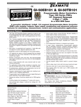
Input Setup
Input Calibration Mode
Select the required noise rejection
to suit the power supply frequency.
If the mains supply is 50 Hz, then
select 50 Hz to reject 50 Hz noise.
Correspondingly, if the mains supply
is 60 Hz, then select 60 Hz to reject
60 Hz noise.
Select between 1 Hz, 10 Hz,
or 50 Hz input sampling rate.
Select the nearest nominal sensor
gain to suit your load cell sensor’s
specifications between 1 mV/V,
2 mV/V, 3 mV/V, or 20 mV/V.
Select the decimal point
position for the required resolution:
• 00000.0 – Tens.
• 0000.00 – Hundreds.
• 000.000 – Thousands.
• 00.0000 – Ten thousands.
Select the required amount of
rounding to be applied to the last
digit. Selecting no rounding counts
every unit, by two’s counts every
second unit, by five’s counts every
fifth unit, and by ten’s counts every
tenth unit.
Input Setup
Theinputsetupmodeallowsyoutoconfigurefiveinputsetupsettingsinlinkedmenus.

Texmate, Inc. Tel. (760) 598-9899
4SG100 (NZ701)
www.texmate.com
Load OFF Load ON
20,000
SPAN Example
ZERO Example
Prog.
SP1SP2 SP4SP3SP5 SP6
Prog.
SP1SP2 SP4SP3SP5 SP6
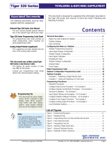
Input Calibration
The inputcalibrationmode provides four individual calibration techniques.
Prog.
SP1 SP2 SP4SP3 SP5 SP6
P
[_ _SELECT
CALIBRATION
TECHNIQUE]
Prog.
SP1 SP2 SP4SP3 SP5 SP6
P
[_ _REMOVE WEIGHT----
PRESS PROGRAM BUTTON
TO ACCEPT]
Prog.
SP1 SP2 SP4SP3 SP5 SP6
[_ _ADD WEIGHT----ENTER
DESIRED SPAN---- PRESS
PROGRAM BUTTON TO
ACCEPT]
Max counts 999999
Min counts 0
P
Prog.
SP1 SP2 SP4SP3 SP5 SP6
Max counts 999999
Min counts –199999
P
[_ _ENTER TOTAL FULL SCALE
WEIGHT OF LOAD CELLS IN
COUNTS]
Prog.
SP1 SP2 SP4SP3 SP5 SP6
Prog.
SP1 SP2 SP4SP3 SP5 SP6
Max counts 999999
Min counts –199999
[_ _ENTER MV/V FROM LOAD
CELL TEST CERTIFICATE]
(NOTE 2MV/V NOMINAL
SENSOR ONLY)
P
Prog.
SP1 SP2 SP4SP3 SP5 SP6
Max counts 2.500
Min counts 1.500
[SET ZERO NOW ?]
P
Prog.
SP1 SP2 SP4SP3 SP5 SP6
P
4 Secs
START
Prog.
SP1 SP2 SP4SP3 SP5 SP6
Prog.
SP1 SP2 SP4SP3 SP5 SP6
P
Zero Maintenance
Input Calibration
See Page 3
YES
YES
OR
OR
Prog.
SP1 SP2 SP4SP3 SP5 SP6
P
P
P
P
Prog.
SP1 SP2 SP4SP3 SP5 SP6
Prog.
SP1 SP2 SP4SP3 SP5 SP6
P
See Pages 5-6
Prog.
SP1 SP2 SP4SP3 SP5 SP6
P
[ENTER KNOWN
WEIGHT---- PRESS PROG
TO ACCEPT OFFSET]
Prog.
SP1 SP2 SP4SP3 SP5 SP6
P
[ADD CAL WEIGHT----
ENTER DESIRED SPAN----
PRESS PROGRAM
BUTTON TO ACCEPT]
Prog.
SP1 SP2 SP4SP3 SP5 SP6
Max counts 999999
Prog.
SP1 SP2 SP4SP3 SP5 SP6
Min counts –199999
P
YES
P
x3 to bypass remaining modes
and return to START
P
P
Max counts 999999
Min counts –199999
P
Input Setup
Remove the calibration weight and set the zero
calibration offset value.
This is a two-step
setting. Both
settings must be
carried out
correctly, zero
then span, for
the controller to
accept the
calibration.
Add together the capacities quoted on the test
certificate of all connected load cells and enter
this figure in counts into the controller.
Note: This must include
all counts before and
after the decimal point
to suit the resolution
required.
Note: This is for use with sensors between
1.5 to 2.5 mV/V only.
Enter the average of the mV/V readings quoted
on the test certificate of all connected load cells.
Note: The mV/V menu
enters a calculated
span only.
Select [YES] to enter the zero offset
calibration value (with load cells
connected) or [NO] to return to the
operational display.
This calibration technique allows you to independently
trim the displayed zero, or enter a zero offset value to
compensate for residual load.
This calibration technique allows you to independently
trim the loaded displayed weight to the required value.
Note, when trimming the span value, the zero/offset
value is automatically re-calculated and entered for
the new scale factor (trimmed span value).
Add the calibration weight to the weighing platform and set the
calibration value. If calibration fails, you will see a “calibration failed”
message displayed twice. Meter goes back to normal operation.

SG100 (NZ701) Texmate, Inc. Tel. (760) 598-9899 5
www.texmate.com
Zero Maintenance
P
P
Prog.
SP1 SP2 SP4SP3 SP5 SP6
Prog.
SP1 SP2SP4SP3SP5 SP6
Prog.
SP1 SP2SP4SP3 SP5 SP6
Prog.
SP1 SP2 SP4SP3SP5 SP6
P
[SET ZERO
MAINTENANCE]
[SET ZERO
MAINTENANCE
PARAMETERS]
Prog.
SP1SP2 SP4SP3SP5 SP6
Prog.
SP1SP2 SP4SP3SP5 SP6
P
Prog.
SP1 SP2SP4SP3SP5 SP6
Prog.
SP1SP2 SP4SP3SP5 SP6
Min
1
Max
254
P
Prog.
SP1 SP2 SP4SP3SP5 SP6
Prog.
SP1SP2 SP4SP3SP5 SP6
Min
0
Max
255
P
Prog.
SP1SP2 SP4SP3SP5 SP6
Prog.
SP1SP2 SP4SP3SP5 SP6
Min
0
Max
65535
Prog.
SP1SP2 SP4SP3SP5 SP6
P
Prog.
SP1SP2 SP4SP3 SP5SP6
Prog.
SP1SP2 SP4SP3SP5 SP6
Min
0
Max
65535
See Page 7
YES
P
P
4 Secs
START
Prog.
SP1 SP2 SP4SP3SP5 SP6
Prog.
SP1 SP2SP4SP3 SP5 SP6
P
Input Calibration
See Page 3
YES
YES
P
Zero Maintenance
See Page 4
x2 to bypass remaining modes
and return to START
Input Setup
Averaging Parameters
x2
See Figure 1
See Figure 2
See Figure 3
Auto Zero Maintenance
Auto zero maintenance is used to automatically compensate
for slow drift in load cell output due to factors such as tem-
perature change, dust accumulation over time, and small
mechanical changes. The controller display maintains zero
provided all of the following three conditions remain within their
programmed parameters:
• Auto zero capture band. Displayed as [AZ_CAP].
• Auto zero motion. Displayed as [AZ_MOT].
• Auto zero aperture window. Displayed as [AZ_APT].
Provided the changes to the load cell remain within the
captureband,motionband,andaperturewindowparame-
ters,thecontrollerautomaticallyzeroes.
Auto Zero Capture Band [AZ_CAP]
See Figure 1. The auto zero capture band is the maximum
number of display counts that the controller will automatically
zero within. The capture band reference point is the accumu-
lated zero counts. If the drift/load on the load cell exceeds the
capture band setting, then the controller stops zeroing and
displays the change.
The capture band setting can be set from 1 to 254 counts, but
should always be set to less than the smallest weight to be
measured.
Zeromaintenanceprovidesanautomaticandmanualmodeforzeroingthecalibratedzerosetting.
Capture
Band
Display
Counts
Prog.
SP1 SP2SP4SP3SP5 SP6
10 Counts
8
Counts
8
12
Counts
12
8 counts is inside
the capture band.
Controller auto zeroes
16 counts is outside
the capture band.
No auto zero,
controller displays
counts
Prog.
SP1 SP2SP4SP3SP5 SP6
Calibrated
Span Range
Calibrated Zero
Accumulated
Zero
Figure 1 – Auto Zero Capture Band

Texmate, Inc. Tel. (760) 598-9899
6SG100 (NZ701)
www.texmate.com
Auto Zero Motion [AZ_MOT]
SeeFigure2.Autozeromotioncontroloperateswithinthe
capture band and provides a rate of change limit setting. The
rate of change setting determines the number of counts per
second allowed within the capture band. This means that even
if the count change is within the capture band, but the speed of
the count change is more than the selected counts per second,
then the controller stops zeroing and displays the change.
The auto zero motion setting can be set from 0 to 255 counts,
but is normally set below the capture band.
Capture
Band
Display
Counts
2s
Prog.
SP1 SP2SP4SP3SP5 SP6
14 Counts
3 Counts
ROC
3 counts rate of change
is inside the capture band
and inside the auto zero
motion setting.
Controller auto zeroes
Prog.
SP1 SP2SP4SP3SP5 SP6
6 Counts
ROC
6 counts rate of change is
inside the capture band,
but outside the auto
zero motion setting.
NO auto zero
Calibrated
Span Range
Calibrated Zero
4
Time
(Seconds) 1s
Auto
Zero
Motion
3 counts
rate of
change
4
6 counts
rate of
change
Auto Zero Aperture Window [AZ_APT]
The auto zero aperture window provides a limit for the number
of counts of zero offset allowed to accumulate relative to the
calibrated zero setting. If the accumulated zero offset becomes
greater than the aperture window, the auto zero function stops
operating and the controller displays the reading.
The suggested limit for the aperture window is 2% of the cali-
brated span. If the controller fails to zero, check for mechanical
or electrical faults.
Display
Counts
Prog.
SP1 SP2SP4SP3SP5 SP6
Prog.
SP1 SP2SP4SP3SP5 SP6
Aperture Window
Setting (Suggested limit
2% of calibrated span range)
Calibrated
Span Range
Calibrated Zero
While accumulated zero
remains within aperture
window. Controller
auto zeroes Accumulated
Zero
Time
Accumulated zero now outside
aperture window.
Auto zero stops, controller
displays counts
Manual Zero
Manually resetting the calibrated zero is initiated from a remote
switch (not supplied) connected through the Pin 4 and 5 at the
rear of the controller (Terminal 2: Pin 4 Common, Pin 5 Manual
Zero).
Manual Zero Aperture Window [AZ_APT]
The manual zero aperture window provides a limit for the num-
ber of counts of zero offset allowed to accumulate relative to the
calibrated zero setting. If the accumulated zero offset becomes
greater than the aperture window, the manual zero function
stops operating and the controller displays the actual reading.
Manual zero shifts the zero position on channel 1 (CH1), but
does not alter the calibrated span range.
The manual zero window limit should be set to no more than 2%
of the load cell span. This reduces the danger of overloading
the load cell and causing possible mechanical damage. If the
controller fails to zero, check for mechanical or electrical faults.
The manual zero offset is held in non-volatile memory and is
retained during a power outage.
Set Display Tare & Reset Display Tare Function
The controller has been programmed with a set display tare and
reset display tare function that operate on the display reading
only.
The set display tare function is used to zero the display. Set dis-
play tare is initiated from a remote switch (not supplied) connect-
ed through Pins 4 and 2 at the rear of the controller (Terminal 2:
Pin 4 Common, Pin 2 Set Display Tare).
The reset display tare function is used to restore the true cali-
brated weight on the display. Reset display tare is initiated from a
remote switch connected through Pins 4 and 1 at the rear of the
controller (Terminal 2: Pin 4 Common, Pin 1 Reset Display Tare).
The set display tare and reset display tare values are not
retained during a power outage.
The set display tare and reset display tare functions are often
used for batching applications.
Figure2–AutoZeroMotion
Figure3–AutoZeroApertureWindow

SG100 (NZ701) Texmate, Inc. Tel. (760) 598-9899 7
www.texmate.com
Averaging Parameters
P
P
Prog.
SP1 SP2 SP4SP3 SP5 SP6
Prog.
SP1 SP2SP4SP3SP5 SP6
P
Prog.
SP1 SP2 SP4SP3SP5 SP6
Prog.
SP1 SP2SP4SP3 SP5 SP6
P
YES
Prog.
SP1SP2 SP4SP3SP5 SP6
Prog.
SP1SP2 SP4SP3 SP5 SP6
Min 0
Max 255
Prog.
SP1SP2 SP4SP3SP5 SP6
Prog.
SP1SP2 SP4SP3 SP5 SP6
Min 0
Max 65535
[SET AVERAGING
PARAMETERS]
P
P
4 Secs
START
Prog.
SP1 SP2 SP4SP3SP5 SP6
Prog.
SP1 SP2 SP4SP3 SP5 SP6
PSee Page 3
YES
See Page 4
See Pages 5-6
Averaging Parameters
Analog Output Scaling
P
YES
x1 to return to START
See Page 8
Zero Maintenance
Input Calibration
Input Setup
x3
Windowed averaging allows you to average a selected number of input signal samples
within a selectable averaging window. This allows you the benefit of a stable signal,
with fast response to change when required.
The number of input signal samples to average over is selected in the [AVE_S] menu.
The size of the averaging window in input signal displayed counts is selected in the
[AVE_W] menu.
See Figure 4. While the signal is being
monitored by the controller, the averag-
ing window tracks the input signal, looks
at the samples, and when it locates a
group of samples within the size of the
window, averaging takes place.
As each new sample comes into the
controller, the last sample in the group is
dropped off. Provided the sample group
remains within the averaging window,
the controller constantly averages the
sample group.
If a sample moves out of the averaging
window, the controller responds quickly
to the change by displaying the non-av-
eraged signal value. When the signal
stabilises, a new averaging window is
established around a sample group and
averaging resumes.
Fast response.
No averaging.
Sampling
Input Signal in Counts
Samples = Averaging Window
e.g. 20
Select the number of
samples in a group.
4 samples have been
selected in this example.
Select the size of the
averaging window in
displayed counts.
Fast response.
No averaging.
Fast response.
No averaging.
Fast response.
No averaging.
Fast response.
No averaging.
Continuous
Averaging.
Figure4–AveragingParameters

Texmate, Inc. Tel. (760) 598-9899
8SG100 (NZ701)
www.texmate.com
Analog Output Scaling
P
Prog.
SP1 SP2SP4SP3 SP5 SP6
Prog.
SP1 SP2 SP4SP3SP5 SP6
P
Prog.
SP1SP2 SP4SP3 SP5SP6
Prog.
SP1SP2 SP4SP3SP5 SP6
Min –199999
Max 999999
Prog.
SP1SP2 SP4SP3SP5 SP6
Prog.
SP1 SP2 SP4SP3SP5 SP6
Min –199999
Max 999999
P
P
[SET ANALOG
OUTPUT SCALING]
P
4 Secs
START
Prog.
SP1 SP2 SP4SP3SP5 SP6
Prog.
SP1 SP2 SP4SP3SP5 SP6
P
See Page 3
YES
See Page 4
See Pages 5-6
YES P
See Page 7
Averaging Parameters
Analog Output Scaling
Zero Maintenance
Input Calibration
Input Setup
x4
Set the counts required
to be displayed for the
calibrated low [ZERO]
analog output setting.
Set the counts required
to be displayed for the
calibrated high [F_SCL]
(full scale) analog output
setting.
Note: There are no limits to the difference between the zero
and full scale settings. The difference can be anywhere
between 1 count and the entire display range of the meter.
The analog output module is a single channel, programmable,
isolated, 16-bit analog output that can be scaled to any desired
span between –199999 to 999999 display counts using the
analog output scaling mode.
See Analog Output Procedures for an analog output scaling pro-
cedure.
Analog Output Module
The analog output module is mounted on the controller’s out-
put carrier board and leaves the factory configured for 4-20
mA output. It can also be user configured for either 0/4-20 mA
or 0-10 V DC, or reverse of either, using acurrent/voltage
selectionheader.
See Analog Output Procedures for a current / voltage selection
header positioning procedure.
Analog Output Calibration
The analog output’s milliamp or voltage output requires to be
calibrated to suit your application. To carry out this procedure,
enter the calibration mode by pressing the and buttons
at the same time. You have entered the brightness mode. You
can remain in this mode and reset the display brightness, or
press the button again to enter the calibration mode.
Calibrating the analog output requires setting the milliamp or
voltage output low [CAL_L] and high [CAL_H] parameters. The
calibrated low and high outputs can be set anywhere between
–0.3 to +21 mA for current or –0.3 V to +10.5 V for voltage.
Once the milliamp or voltage output is calibrated, the analog
output can be easily rescaled (setting zero and full scale) using
the analog output scaling mode without having to recalibrate
the milliamp or voltage output. The low and high milliamp out-
put signal values follow the new span range.
See Analog Output Procedures for an analog milliamp or volt-
age output calibration procedure.

SG100 (NZ701) Texmate, Inc. Tel. (760) 598-9899 9
www.texmate.com
Use buttons
to set the calibration
low setting
Calibration
1st digit enters Calibration
Procedures mode
3rddigit selects analog output
channel (Select CH1 only)
2nddigit enters Calibrate Analog
Output mA/V (requires multimeter
connected to pins 1 and 2)
Load Cell Controller – Programming Logic Tree
Setpoint Programming Mode
OtherCalibrationSettings
CalibrateAnalogOutput(mAOutput)
Together
Use buttons to
set the calibration
high setting
1st digit enters Related
Calibration Functions mode
3rddigit selects required channel for
serial comms.
Note, select CH1 only
2nddigit enters Serial
Communications Properties mode
OptionalSerialPortSettings(Factorypre-selectedforCH1)
HI_1: enter and set parameters for setpoint SP1
HI_2: enter and set parameters for setpoint SP2
LO_1: enter and set parameters for setpoint SP3
LO_2: enter and set parameters for setpoint SP4
Together
Use buttons
to set baud rate
Use buttons
to set parity
Use buttons
to set address
SP
Above
ACTIVATION
Both setpoints HI_1 and HI_2 activate
above the setpoint activation value.
SP
Below
ACTIVATION
Both setpoints LO_1 and LO_2 activate
below the setpoint activation value.
Brightness BRIGHT maximum 7
DULL minimum 0
Full serial port configuration details are available in the document:
Serial Communications Module Supplement (NZ202).
Visit www.texmate.com and browse the literature page for the documentation you require.
Advanced Function Programming
The SG100 belongs to the Tiger 320 Series range of controllers and uses the Tiger 320
Operating System. All functions available in the Tiger 320 Operating System are available to
the SG100, but the codes are hidden from the operator. If any of these advanced functions
are required for the SG100, the codes can be restored by removing code blanking. To remove
code blanking, carry out the procedures on Page 10, Code Blanking & Macro Checking
Procedure.
Contact Texmate for further information on advanced functions available with the SG100.

Texmate, Inc. Tel. (760) 598-9899
10 SG100 (NZ701)
www.texmate.com
Code Blanking & Macro Checking Procedure
Prog.
SP1 SP2SP4SP3SP5 SP6
Prog.
SP1 SP2SP4SP3 SP5SP6
Prog.
SP1 SP2SP4SP3SP5 SP6
Press
and
hold
Step 1
Step 2
While holding both
buttons, press the Prog.
button.
Step 2
Step 3
Operational Display
Example
Release
after
pressing
Prog.
Press
Code
Blanking
CODE BLANKING & MACRO CHECK PROCEDURE
Press and hold
the and
buttons
While holding both
buttons, press the Prog.
button.
Prog.
SP1 SP2SP4SP3 SP5SP6
Release the
the and
buttons and hold
the Prog. button
for approx. 1 sec
then release
Release
after 1
sec
Prog.
SP1 SP2SP4SP3SP5 SP6
Step 4
Press the button to switch
code blanking OFF
Press
1
NOTE: Unless
otherwise requested,
the factory default
setting is oFF.
Prog.
SP1 SP2SP4SP3SP5 SP6
Operational Display
Prog.
SP1 SP2SP4SP3 SP5SP6
Press
1
Step 7
Press the Prog. button.
Prog.
SP1 SP2SP4SP3 SP5SP6
Press
1
Prog.
SP1 SP2SP4SP3SP5 SP6
Example
Macro
Prog.
SP1 SP2SP4SP3SP5 SP6
Step 6
Press the button to switch
the macro OFF
Press
1
Step 5
Press the Prog. button.
NOTE: Unless
otherwise requested,
the factory default
setting is oFF.
Code Blanking & Macro
Checking Procedure
START HERE
The SG100’s Tiger 320 Series operating system is blanked out
to the operator to prevent accidental configuration changes. To
configure the SG100 for any advanced functions, the operating
system’s programming codes can be accessed by removing
code blanking.
To remove code blanking, carry out the procedures in the Code
Blanking & Macro Checking Procedure opposite.
Contact Texmate for further information on advanced functions
available with the SG100.

SG100 (NZ701) Texmate, Inc. Tel. (760) 598-9899 11
www.texmate.com
6
W
4W
PIN 1
PIN 2
PIN 3
PIN 4
PIN 5
PIN 6
PIN 7
PIN 8
– SENSE
+ EXC
+ SENSE
INPUT SIGNAL HIGH
INPUT SIGNAL LOW
- EXC
GUARD
NOT USED
263F
6
W
4W
PIN 1
PIN 2
PIN 3
PIN 4
PIN 5
PIN 6
PIN 7
PIN 8
– SENSE
+ EXC
+ SENSE
INPUT SIGNAL HIGH
INPUT SIGNAL LOW
- EXC
GUARD
NOT USED
263F
4or6-wireBridgeHeaderPositioning
STEPA DisconnectthePowerSupplyandInput/Output
Connectors
WARNING
AC and DC power supply voltages are
hazardous.Makesurethepowersupply
is isolated before disconnecting from
thecontroller.
1) Pull the AC power supply connector block
from the AC power input pins.
2) Pull all other input and output connectors
from their sockets.
STEPB RemovetheRearCoverfromtheSG100
1) Using a small flat-blade screwdriver, press
down lightly to release the catch on the top of
the case and gently lever outwards.
2) Repeat for the other top catch.
3) With both top catches free, pull the rear cover
away from the SG100.
!
Header set
for4-wire
STEP C Remove the Input Module
1) Pull the input module (bottom left board when
viewed from rear) until it is free from the
SG100 case.
STEP D Select the Correct Header Setting
1) If not in the correct position, pull the header
from its pins and reposition it to suit the load
cell input signal type: 4-WIRE
STEP E Replace the Input Module Board
1) Gently push the input module board back into
the SG100 case, taking care to correctly align
the board with the slots on the case.
STEP F Replace the Rear Cover
1) Place the top catches into their respective
slots and swing the bottom of the rear cover
towards the SG100 until the bottom catches
slide home.
2) Press the rear cover firmly into place.
STEPG ReconnectthePowerSupplyandInput/Output
Connectors
1) Ensure the power supply is still isolated.
2) Reconnect the AC power supply connector
block to the AC power input pins.
3) Reconnect the input and output connectors.
4) Remove the isolation from the power supply.
The power and input signal should be restored and the
SG100shouldbeintheoperationaldisplay.
Input Signal Setup Procedures
To reposition the 4-wire/6-wire bridge selection header, pro-
ceed as follows:
Note:
The load cell input can be either a 4-wire or 6-wire
bridge configuration. The selection header has been
preset for 4-wire before leaving the factory.
The following procedure describes how to change
the header position if necessary.
6-wireBridgeConfiguration
4-wireBridgeConfiguration
Header set
for6-wire
Figure5–RearCoverRemoval
Figure6–LoadCellConfiguration
TOP VIEW
To open the rear cover,
use a small flat-blade
screwdriver. Press
down lightly to release
catch on top or bottom
of case and lever
outwards.
Rear
Cover
PART SIDE VIEW
To replace the rear cover, place the top
catches into their respective slots and
swing the bottom of the rear cover
towards the controller until the bottom
catches slide home. Press the rear
cover firmly into place.
Top Catch
Bottom
Catch
Top Catch

Texmate, Inc. Tel. (760) 598-9899
12 SG100 (NZ701)
www.texmate.com
Selection Header Positioning
STEPA DisconnectthePowerSupplyandInput/Output
Connectors
WARNING
AC and DC power supply voltages are
hazardous.Makesurethepowersupply
is isolated before disconnecting from
theSG100.
1) Pull the AC power supply connector block
from the AC power input pins.
2) Pull all other input and output connectors
from their sockets.
STEPB RemovetheRearCoverfromtheSG100
1) Using a small flat-blade screwdriver, press
down lightly to release the catch on the top of
the case and gently lever outwards.
2) Repeat for the other top catch.
3) With both top catches free, pull the rear cover
away from the SG100.
!
STEP C Remove the Carrier Board
1) Pull the carrier board (top board) until it is
free from the SG100 case.
STEP D Select the Correct Analog Output
Selection Header Setting
1) If not in the correct position, pull the header
from its pins and reposition it to suit the ana-
log output signal: VOLTAGE or
STEP E Replace the Carrier Board
1) Gently push the carrier board back into the
controller case, taking care to correctly align
the board with the slots on the SG100 case.
STEP F Replace the Rear Cover
1) Place the top catches into their respective
slots and swing the bottom of the rear cover
towards the controller until the bottom catches
slide home.
2) Press the rear cover firmly into place.
STEPG ReconnectthePowerSupplyandInput/Output
Connectors
1) Ensure the power supply is still isolated.
2) Reconnect the AC power supply connector
block to the AC power input pins.
3) Reconnect the input and output connectors.
4) Remove the isolation from the power supply.
The power and input signal should be restored and the
SG100shouldbeintheoperationaldisplay.
Analog Output Procedures
The analog output selection header can be positioned for cur-
rent (0/4 to 20 mA) or voltage (0 to 10 V DC) output. To change
the header selection, the output carrier board must be removed
from the SG100.
To reposition the analog output selection header, proceed as
follows:
Note:
The analog output current / voltage selection header
has been preset for CURRENT before leaving the
factory.
The following procedure describes how to change
the header position if necessary.
TOP VIEW
To open the rear cover,
use a small flat-blade
screwdriver. Press
down lightly to release
catch on top or bottom
of case and lever
outwards.
Rear
Cover
PART SIDE VIEW
To replace the rear cover, place the top
catches into their respective slots and
swing the bottom of the rear cover
towards the controller until the bottom
catches slide home. Press the rear
cover firmly into place.
Top Catch
Bottom
Catch
Top Catch
Figure 7 – Rear Cover Removal
ANALOG OUTPUT
SELECTION
CURRENT
VOLTAGE
Analog Output
Selection Header
Output
Carrier
Board
Analog Output
Module(located
belowOutput
CarrierBoard)
Figure8–AnalogOutputSelectionHeaderPlacement

SG100 (NZ701) Texmate, Inc. Tel. (760) 598-9899 13
www.texmate.com
AnalogOutputCalibrationProcedures
1) See Figure 8. Make sure the analog output selection header
on the analog output module is set in the appropriate position:
VOLTAGE or CURRENT (Factory preset to CURRENT).
2) See Figure 9. Connect a multimeter to the analog output con-
nector at the rear of the meter (Terminal 4: Pin 1 positive, Pin 2
negative).
Prog.
SP1 SP2SP4SP3SP5 SP6
Prog.
SP1 SP2SP4SP3SP5 SP6
Prog.
SP1 SP2SP4SP3SP5 SP6
Prog.
SP1 SP2SP4SP3SP5 SP6
Prog.
SP1 SP2SP4SP3SP5 SP6
Prog.
SP1 SP2SP4SP3SP5 SP6
Prog.
SP1 SP2SP4SP3SP5 SP6
Prog.
SP1 SP2SP4SP3SP5 SP6
Prog.
SP1 SP2SP4SP3SP5 SP6
To
Step
6
From Step 5
OR
Press
1
Press
1
Press
for 4
secs
Step 1
Step 2
Step 3
Step 4
Step 5
Step 6
Step 7
Step 8
Enter the
Scrolling Text
Menus
Pass Input Setup
Mode, Calibration
Mode, Zero
Maintenance Mode,
Averaging Parameters
Mode
Operational Display
Enter [ZERO]
setting mode
Adjust the display to 50
counts for the low analog
output signal
Example
OR
ANALOG OUTPUT SCALING
Enter the Analog Output
Scaling Mode
Adjust the display to 3000
high analog output
signal counts
To calibrate the analog output mA/V
output, see procedure: Calibrate the
Analog Output Signal on next page.
Enter the [F_SCL]
Setting mode
Note:
The scale settings can be
changed at any time without
having to recalibrate the
analog mA/V output signal.
Save scale settings
(zero and full scale)
and return to the
Operational Display
Prog.
SP1 SP2SP4SP3SP5 SP6
Press
x4
Prog.
SP1 SP2SP4SP3SP5 SP6
Press
1
Prog.
SP1 SP2SP4SP3SP5 SP6
Press
1
Prog.
SP1 SP2SP4SP3SP5 SP6
Operational Display
Scale Analog Output
START HERE
3) Make sure the multimeter is set to read the appropriate signal
type: volts or milliamps.
4) Carry out the analog output scaling procedure to set zero and
full scale settings.
5) If required, carry out the analog output calibration procedure to
calibrate the millamp output low and high settings.
Analog Output Scaling Mode
Example
In the following example analog output scaling procedure, we
decribe how to scale the analog output signal for 4 to 20 mA
over a range of 50 to 3000 counts. With a display of 50 counts,
the analog output must be 4.000 mA. With a display of 3000
counts, the analog output must be 20 mA.
Pin 3+
Pin 2–
MULTIMETER
V
V
mV
mA
A
OFF
µA
COM V Ω
mA µA
A
PEAK MIN MAX
MIN MAX RANGE HOLD
Hz
REL
Ω
Ω
–
+
SP1 SP2SP4SP3SP5 SP6
Prog.
SP1 SP2SP4SP3SP5 SP6
TERMINAL 4
Figure9–MultimetertoSG100Connections

Texmate, Inc. Tel. (760) 598-9899
14 SG100 (NZ701)
www.texmate.com
Analog Output Calibration Mode Procedure
Example
In the following example analog output calibration procedure,
with the analog output already scaled over a range of 50 to
3000 counts for 4 to 20 mA, calibrate the low mA output to
4.000 mA and the high mA output to 20 mA.
Prog.
SP1SP2 SP4SP3SP5 SP6
Prog.
SP1 SP2 SP4SP3SP5 SP6
Prog.
SP1 SP2SP4SP3SP5 SP6
Prog.
SP1 SP2SP4SP3SP5 SP6
Prog.
SP1 SP2 SP4SP3 SP5 SP6
Prog.
SP1 SP2 SP4SP3 SP5 SP6
Prog.
SP1 SP2 SP4SP3 SP5 SP6
X
Ensure the low
analog output signal
reading [CAL_LO] on
the multimeter display
is 4.00 mA.
If not correct,
press the OR
button on the
SG100 controller
until the reading
on the multimeter
display is correct.
If not 20 mA,
press the
OR button
on the SG100
controller until
the reading on
the multimeter
display is
correct.
To
Step
7
From Step 6
Press
1
Step 3
Step 4
Step 5
Set CAL to [151]:
1st Digit = 1 Selects calibration procedures
2nd Digit = 5 Selects calibrate analog output
3rd Digit = 1 Select analog output 1 for calibration
X
Step 10
Step 11
Save calibration mode
[000] setting and enter
Code 1
Operational Display
Exit Code 1 and return
to the operational display
Enter analog output
low signal calibration
mode
X
X
Step 6
Step 8
Example
X
Save the low analog
output signal setting.
Enter analog output
high signal calibration
mode
Step 9
Step 7
X
Press
1
Ensure the high
analog output
signal reading
[CAL_HI] on the
multimeter display
is 20 mA.
Reset calibration
mode setting
to [000]
Save the high analog
output signal setting.
Return to the calibration
mode [CAL] menu
Press
1
MULTIMETER
V
V
mV
mA
A
OFF
µA
COM V Ω
mA µA
A
PEAK MIN MAX
MIN MAX RANGE HOLD
Hz
REL
Ω
Ω
–
+
MULTIMETER
V
V
mV
mA
A
OFF
µA
COM V Ω
mA µA
A
PEAK MIN MAX
MIN MAX RANGE HOLD
Hz
REL
Ω
Ω
–
+
Press
1
MULTIMETER
V
V
mV
mA
A
OFF
µA
COM V Ω
mA µA
A
PEAK MIN MAX
MIN MAX RANGE HOLD
Hz
REL
Ω
Ω
–
+
MULTIMETER
V
V
mV
mA
A
OFF
µA
COM V Ω
mA µA
A
PEAK MIN MAX
MIN MAXRANGEHOLD
Hz
REL
Ω
Ω
–
+
Pin 3+
Pin 2–
TERMINAL 4
Pin 3+
Pin 2–
TERMINAL 4
Pin 3+
Pin 2–
TERMINAL 4
TERMINAL 4
Prog.
SP1 SP2SP4SP3 SP5SP6
OR
Prog.
SP1 SP2 SP4SP3 SP5 SP6
Prog.
SP1 SP2 SP4SP3 SP5SP6
OR
Prog.
SP1SP2 SP4SP3 SP5SP6
Prog.
SP1SP2 SP4SP3 SP5 SP6
Prog.
SP1 SP2 SP4SP3SP5 SP6
OR
Prog.
SP1 SP2 SP4SP3SP5 SP6
Prog.
SP1 SP2 SP4SP3SP5 SP6
Prog.
SP1 SP2SP4SP3SP5 SP6
Prog.
SP1 SP2SP4SP3SP5 SP6
Step 1
Enter the
Brightness Mode
Operational Display
Prog.
SP1 SP2 SP4SP3SP5 SP6
Prog.
SP1 SP2 SP4SP3SP5 SP6
Press
1
Step 2
Enter the
Calibration Mode
Pin 3+
Pin 2–
OR
Press
at same
time
Press
at same
time
Example
Press
at same
time
Press
at same
time
CalibrateAnalogMilliamp/
Voltage Output Signal
START HERE
Note:
The analog output has been pre-configured as a
milliamp output before leaving the factory.
The following procedure describes how to recali-
brate the milliamp output (or voltage if reset) over 4
to 20 mA if required.

SG100 (NZ701) Texmate, Inc. Tel. (760) 598-9899 15
www.texmate.com
Figure10–RearPanelPinoutDiagram
2 3
1 2
1 2 3 4
Input Module
up to
345
2
1
5
Dual Analog
Output ONLY
61
Serial Output
Function Pins
TEST COM Manual
Zero
Analog Output
TERMINAL 1
TERMINAL 6
1
1
TERMINAL 2
TERMINAL 4
TERMINAL 5
26
Output Module
(All output modules use up to 8 pins except
the multi-I/O module which uses 26 pins)
POWER
2 3 4 5 6 7 8 Reset
Display
Tare
Set
Display
Tare
Connector Pinouts
The SG100 uses plug-in type screw terminal connectors for
most input and output connections, an RJ-11 phone connector
for the optional RS-232 or RS-485 serial outputs, and an RJ-45
phone connector for the optional Ethernet output.
All external connections to the SG100 is via the following six
connector terminal blocks located at the rear of the SG100:
• Terminal 1: Input Signals.
• Terminal 2: Function Pins.
• Power: AC / DC Power Supply.
• Terminal 4: Analog Output.
• Terminal 5: Serial Output.
• Terminal 6: Relay Output or Multi-I/O Module.
Pin Name Description
Connector
1
Input Signals
Reset Display Tare
TERMINAL 1
TERMINAL2
Function Pins
1AC Neutral / DC –
POWER
Auto Sensing
AC/DCPower
Supply
The power connector supplies AC / DC power to the controller via a standard high voltage or
optional low voltage auto-sensing power supply mounted on the main board.
PS1: Standard High Voltage option. 85-265 V AC / 95-300 V DC.
PS2: Optional Low Voltage option. 15-48 V AC / 10-72 V DC.
2AC Line / DC +
Pins 1 up to 8
Pins 1 to 5
Pins 1 and 2
For further details on the function pins, contact Texmate.
1– Sense
2+Excitation
3
Input Signal Low
4
+ Sense
5
Input Signal High
6
Not Used
7
–Excitation
8
Guard
6
W
4W
PIN 1
PIN 2
PIN 3
PIN 4
PIN 5
PIN 6
PIN 7
PIN 8
– SENSE
+ EXC
+ SENSE
INPUT SIGNAL HIGH
INPUT SIGNAL LOW
- EXC
GUARD
NOT USED
263F
6-wire Bridge Configuration
(for 4-wire bridge disconnect
sense leads)
Input Module ISS1 / ISS2
Connecting Pin 1 (reset display tare) to Pin 4 (common) with a remote
switch (not supplied), the load cell reading on the display is returned to the
true calibrated weight on the display.
2Set Display Tare
Connecting Pin 5 (manual zero pin) to Pin 4 (common) with a remote switch
(not supplied), manually resets the calibrated zero.
3
Manual Zero
Pin 3 (display test and reset pin) provides a test of the controller’s display
and resets the microprocessor when Pin 3 is connected to Pin 4.
4
Display Test and
Reset
To activate the hold, test and reset, or lock pins from the rear of the control-
ler, the respective pins have to be connected to the common pin.
5
Common
Connecting Pin 2 (set display tare) to Pin 4 (common) with a remote switch
(not supplied) the load cell reading on the display can be zeroed (tare).
Figure 11 – Terminal Connectors
WARNING: AC and DC input signals and power
supply voltages can be hazardous. Do not connect live
wirestoscrewterminalplugs,anddonotinsert,remove,
orhandlescrewterminalplugswithlivewiresconnected.
!
HOLD
TEST
LOCK
COM
4
23
1
CAPTURE
5
TERMINAL 2
SET TARE
RESET TARE
MANUAL ZERO

Texmate, Inc. Tel. (760) 598-9899
16 SG100 (NZ701)
www.texmate.com
Pin No.
1
2
3
4
5
6
RS-485 (ASCII or Modbus) RJ-11 Socket
B (Low)
A (High)
+5 VDC to power external converters
Isolated Ground
Reserved for future use
Reserved for future use
Single Output Dual Output
7
8
Not applicable
Not applicable
Not applicable
Not applicable
B1
A
B
0 V1
0 V
A1
345
261
STANDARD CARRIER BOARD
RJ-11
1
3
Positive (+)
Positive (+)
TERMINAL4
Analog Outputs
Positive for optional Dual Analog Output.
Positive for Analog Output
2Negative (–) Negative for Analog Output.
TERMINAL5
Serial Outputs
TERMINAL6
Relay
Outputs
TERMINAL 6 connects electromechanical and
solid state relays (SSRs) to external applications.
Pins 1 ,2 and 3
Pins 1 up to 8
TERMINAL 5 connects the serial output module to external devices.
The standard carrier board supports an RS-485 ASCII or Modbus serial card connect-
ed thru an RJ-11 socket.
Pins 1 up to 8
TERMINAL 4 connects the analog output module to external devices. A single 0/4 to 20 mA (standard) or 0 to 10 V DC (optional) is
supported on the standard or Ethernet carrier board.
Pin Name Description
Connector
Order Code
OR34 5A5A5A5A
SP4 SP3 SP2 SP1
1 2 3 54 6 7 8
SP1SP2SP3SP4
1
2
3
4
5
6
7
8
Normally Open SP4
Common SP4
Normally Open SP3
Common SP3
Normally Open SP2
Common SP2
Normally Open SP1
Common SP1
Relay Module with Four 4 A
Form A Relays
Order Code
OR12
- -
SP2 SP4 SP1 SP3
10A10A
1 2 3 54 6 7 8
SP3SP1SP4SP2
1
2
3
4
5
6
7
8
Normally Open SP2
Normally Closed SP2
Common SP2
N/C
Normally Open SP1
Normally Closed SP1
Common SP1
N/C
Relay Module with Two 9 A
Form C Relays
Relay Module
OR34
Relay Modules
OR12
Depending on the number of relays, standard
plug-in relay boards use up to 8 pins.

SG100 (NZ701) Texmate, Inc. Tel. (760) 598-9899 17
www.texmate.com
Short Depth 96X48 Separated Display
OP-DI/RDISP ... Remote Display Connection for DI - w/Cable & Standard Display...... $45
OP-DI/RDND ... Remote Display Connection for DI - w/Cable & No Display (order code ND
must be added to the order, see Display Options) ................................. $25
96X48 DIN Rail Mounting with and without Separated Display
OP-DI/RD-DR .... Remote Display Conn. for DI - w/Cable, Din Rail Mount & Standard Disp ... $55
OP-DI/RDND-D .. Remote Display Connection for DI - w/Cable, Din Rail Mount & No Display (order
code ND must be added to the order, see Display Options) ............................. $35
Installation
96 mm
(3.78")
48 mm
(1.89")
3.9 mm
(0.15") typical
FRONT VIEW
1/8 DIN 96x48mm
Texmate's 96x48 mm case
is particularly suitable for
mounting in mosaic panels
or insulative panels up to 2"
thick. They can also stack
mount, 2 up in existing
cutouts for 1/4 DIN (96x96
mm) or 4 up in 1/2 DIN
(96X192 mm).
Removable
Key-lock
Cam
Opening
Safety
Catch
Clear Lockable NEMA 4X
Splash Proof Cover
P/N:(OP-N4/96x48)
40.8 mm
(1.61")
117 mm
(4.61")
SIDE VIEW
5.3 mm
(0.21")
3.7 mm
(0.15")
43.4 mm
(1.71")
DIN Cutout spacers
Straight-thru Connector for
meters with output board
20 mm (0.79")
Right-angled Connector
11.8 mm (0.47")
PANEL CUTOUT
Case will mount in standard 1/8 DIN coutouts
45 mm
(1.77")
Snug Fitting
Mosaic Fitting
92 mm
(3.62")
Loose Fitting
91.6 mm
(3.6")
40.8 mm
(1.61")
8 places
3 12")
8 places
4 mm
(0.16") 43.4 mm
(1.71")
1/8 DIN
Cutout spacers
87.4 mm
(3.45")
Panel adaptor plates are
available to retrofit most
existing panel cutouts.
For additional strength, extra Mounting
Slide Clips can be ordered and doubled up
one behind the other. P/N: (75-DMTCLIPF)
TOP VIEW
87.4 mm
(3.45")
mosaic
fitting
95.4 mm
(3.77")
Max. panel thickness
50mm
(1.97")
96 mm
(3.78")
91.6 mm
(3.6")
DIN
Cutout
Spacer
To open rear cover,
use a small flat
blade screw driver.
Press down lightly to
release catch on top
or bottom of case
and lever outwards.
4.7 mm
(0.19")
DIN Cutout Spacer
2 mm
(0.08")
Connector
Socket
Prog.
SP1
SP1SP2 SP4SP3SP5 SP6
Prog.
SP1
SP1SP2 SP4SP3SP5 SP6
Prog.
SP1SP2 SP4SP3SP5 SP6
96x48 SG100.eps
Prog.
SP3 SP5 SP6
SP1 SP4
SP2
Metal Surround Case: These dimensions are increased
by 1.6 mm (0.06") when the metal surround case is installed.
Various bezel
colors are available.
Black is standard.
When extra panel
mounting tightness is
required, order the
optional screw mount clip.
P/N:(OP-MTLCLIP)
Metal Surround Case
(P/N: OP-MTL96X48)
NOTE: The Metal Surround Case
is pre-installed at the factory and cannot
be removed without damage to the case.
Metal Surround Case uses
Metal Screw Mount Clips and
has a max. panel thickness
mounting of 15.5 mm
(0.61").
STEP A Prepare the Panel
1) Cut a hole in the panel to suit the panel cut-
out. See panel cutout sizes above.
STEP B Install the Meter
1) Remove both mounting clips from the meter.
2) Push the meter into the panel cutout from the
front of the panel.
3) Attach both mounting clips to the meter from
the rear of the panel and push them towards
the front of the panel until the meter is firmly
held.
STEPC ConnecttheCables
1) Connect all input and output signal cables to the
connector pins (See Connector Pinouts for details).
2) Connect the power cables to the connector pins
(See Connector Pinouts for details).
WARNING
AC and DC power supply voltag-
es are hazardous. Make sure the
power supply is isolated before
connectingtothemeter.
!
123
Installation Procedure
1
2
3
Figure12–SG100InstallationSequence
Optional Remote Shallow-depth Display and DIN-rail Mounting
An optional remote shallow-depth display is available for applications
with minimal panel depth. The controller case can then be mounted in
a convenient position inside the panel, or externally DIN-rail mounted.
6-wire Display
Connector
96x48 mm
Short Depth Case
Remote
Display PCB
96x48 mm Case
DIN Rail Mounting
Remote Displays

Texmate, Inc. Tel. (760) 598-9899
18 SG100 (NZ701)
www.texmate.com
Installation Guidelines
Installation
1. Install and wire meter per local applicable codes/
regulations, the particular application, and good instal-
lation practices.
2. Install meter in a location that does not exceed the
maximum operating temperature and that provides
good air circulation.
3. Separate input/output leads from power lines to pro-
tect the meter from external noise. Input/output leads
should be routed as far away as possible from con-
tactors, control relays, transformers and other noisy
components. Shielding cables for input/output leads is
recommended with shield connection to earth ground
near the meter preferred.
4. A circuit breaker or disconnect switch is required to
disconnect power to the meter. The breaker/switch
should be in close proximity to the meter and marked
as the disconnecting device for the meter or meter cir-
cuit. The circuit breaker or wall switch must be rated
for the applied voltage (e.g., 120VAC or 240VAC) and
current appropriate for the electrical application (e.g.,
15A or 20A).
5. See Case Dimensions section for panel cutout infor-
mation.
6. See Connector Pinouts section for wiring.
7. Use 28-12 AWG wiring, minimum 90˚C (HH) tem-
perature rating. Strip wire approximately 0.3 in. (7-8
mm).
8. Recommended torque on all terminal plug screws is
4.5 lb-in (0.51 N-m).
!

SG100 (NZ701) Texmate, Inc. Tel. (760) 598-9899 19
www.texmate.com
This user’s manual is designed to provide you with the informa-
tion required to connect an SG100 controller to a load cell input
and configure it to operate in a silo or tank weighing application.
The SG100 has a range of built-in functions available to perform
advanced functions that include totalizing, linearization, data
logging, and many more. The four setpoints also have built-in
advanced functions that include setpoint latching, reset, track-
ing, hysteresis and deviation, PID, and seven timer modes.
Advanced Functions and Options
As well as the RS-485 serial output, there are a number of
advanced isolated communications options available such as
Modbus protocol RS-232 and Ethernet.
Should you wish to use any of the remaining built-in functions
available with all SG range controllers, contact Texmate for
further information.
Application Examples
Prog.
SP1 SP2 SP4SP3 SP5 SP6
Alarm
Silo Weighing Application
with 3 averaged support load cells,
On/Off relay control dispensing,
communicate data via 3rd party wireless
bridges for data analytics applications.
On/O Relay
Control
from Meter
Parallel
connection
Add a second
SG-100 here
for Precision
Dispensing
Coumputer
running your
data analytics
program
Wireless
Bridge
Wireless
Bridge
Junction
Box
Ethernet
RS-485
4-20mA
Flow Control
from Meter
Single Channel Milk Tank
Weighing Application
with 4 Averaged
Support Load Cells
Parallel
connection
Prog.
SP1 SP2 SP4SP3 SP5 SP6
Junction
Box

Texmate, Inc. Tel. (760) 598-9899
20 SG100 (NZ701)
www.texmate.com
Ordering Information
BASIC MODEL # DISPLAY POWER SUPPLY INPUT ANALOG OUTPUT COMMUNICATION RELAY DATA LOGGING
SG100 DR(red) PS1(90-265VAC/VDC) ISS4 (60Hz 24bit) AIC(4-20mA) S4 (RS-485 ASCII) OR12 (two 9A FormC) 32Kbit (88 samples)
DISPLAY POWER SUPPLY INPUT ANALOG OUTPUT COMMUNICATION RELAY DATA LOGGING
DG(green) PS2(15-48VAC/VDC) ISS3 (50Hz 24bit) AIV(0-10VDC) S6 (RS-485 Modbus)
S2 (RS-232 ASCII)
S5 (RS-232 Modbus)
S8 (Ethernet ASCII)
S9 (Ethernet Modbus)
OR34 (four 4A FormA)
OP-P1MB/R-T
(1024Kbit (3984 Samples)
with Real Time Clock)
Pre-loaded Configuration (ordering code with this configuration : SG100-DR-PS1-ISS4-AIC-S4-OR12)
Custom Options: call Texmate for availability
WARRANTY
Texmate warrants that its proDXcts are free from defects in material and workmanship under
normal use and service for a period of one year from date of shipment. Texmate’s obligations
under this warranty are limited to replacement or repair, at its option, at its factory, of any of
the proDXcts which shall, within the applicable period after shipment, be returned to Texmate’s
facility, transportation charges pre-paid, and which are, after examination, disclosed to the sat-
isfaction of Texmate to be thus defective. The warranty shall not apply to any equipment which
shall have been repaired or altered, except by Texmate, or which shall have been subjected
to misuse, negligence, or accident. In no case shall Texmate’s liability exceed the original pur-
chase price. The aforementioned provisions do not extend the original warranty period of any
proDXct which has been either repaired or replaced by Texmate.
USER’S RESPONSIBILITY
We are pleased to offer suggestions on the use of our various proDXcts either by way of printed
matter or through direct contact with our sales/application engineering staff. However, since
we have no control over the use of our proDXcts once they are shipped, NO WARRANTY
WHETHER OF MERCHANTABILITY, FITNESS FOR PURPOSE, OR OTHERWISE is made
beyond the repair, replacement, or refund of purchase price at the sole discretion of Texmate.
Users shall determine the suitability of the proDXct for the intended application before using,
and the users assume all risk and liability whatsoever in connection therewith, regardless
of any of our suggestions or statements as to application or construction. In no event shall
Texmate’s liability, in law or otherwise, be in excess of the purchase price of the proDXct.
Texmate cannot assume responsibility for any circuitry described. No circuit patent or software
licenses are implied. Texmate reserves the right to change circuitry, operating software, speci-
fications, and prices without notice at any time.
Forproductdetailsvisitwww.texmate.com
Local Distributor Address
450 State Place • Escondido, CA 92029
Tel: 1-760-598-9899 • USA 1-800-839-6283 • That’s 1-800-TEXMATE
Fax: 1-760-598-9828 • Email: [email protected] • Web: www.texmate.com
Copyright © 2018 Texmate Inc. All Right Reserved.
When you order SG100, your get the following conguration with a pre-loaded Weighing Controller application. Pease call Texmate
for procing and availability of the listed options. Additional accessories may be needed depending on your communication options,
please caontct Texmate to determin which accessories you may need for your application.
/