Page is loading ...

www.adb-air.com
Airfield Lighting
Product Solutions Catalog
Users ManualUsers Manual
L-804 Elevated Runway
Guard Light
Incandescent, Medium-Intensity ERGL
96A0218, Rev. X,

L-804 Elevated Runway Guard Light
96A0218 Rev. X
DISCLAIMER / WARRANTY
© ADB bvba All Rights Reservedii
A.0 Disclaimer /
Standard Warranty
A.1 CE certification The equipment listed as CE certified means that the product complies with the essential requirements
concerning safety and hygiene. The directives that have been taken into consideration in the design are
available on written request to ADB.
A.2 ETL certification The equipment listed as ETL certified means that the product complies with the essential requirements
concerning safety and FAA Airfield regulations. The directives that have been taken into consideration in
the design are available on written request to ADB.
A.3 LED Product
Guarantee
Where applicable, per FAA EB67(applicable edition), ADB L858(L) Airfield Guidance Signs are warranted
against electrical defects in design or manufacture of the LED or LED specific circuitry for a period of 4
years. ADB LED light fixtures (with the exception of obstruction lighting) are warranted against
mechanical and physical defects in design or manufacture for a period of 12 months from date of
installation; and are warranted against electrical defects in design or manufacture of the LED or LED
specific circuitry for a period of 4 years per FAA EB67 (applicable edition).
NOTE: See your sales order contract for a complete warranty description. In some specific cases,
deviations are (to be) accepted in the contract, which will supersede the standard warranty.
A.4 Standard Product
Guarantee
Products of ADB manufacture are guaranteed against mechanical, electrical, and physical defects
(excluding lamps) which may occur during proper and normal use for a period of one year from the date
of installation or 2 years from date of shipment and are guaranteed to be merchantable and fit for the
ordinary purposes for which such products are made. ADB L858 Airfield Guidance Signs are warranted
against mechanical and physical defects in design or manufacture for a period of 2 years from date of
installation per FAA AC 150/5345-44 (applicable edition).
NOTE: See your sales order contract for a complete warranty description.
A.5 All Products LED Products of ADB, manufactured and sold by ADB or its licensed representatives, meets the
corresponding requirements of FAA, ICAO and IEC.
ADB will correct by repair or replacement per the applicable guarantee above, at its option, equipment or
parts which fail because of mechanical, electrical or physical defects, provided that the goods have been
properly handled and stored prior to installation, properly installed and properly operated after installation,
and provided further that Buyer gives ADB Airfield Solutions written notice of such defects after delivery of
the goods to Buyer. Refer to the Safety section for more information on Material Handling Precautions
and Storage precautions that must be followed.
ADB reserves the right to examine goods upon which a claim is made. Said goods must be presented in
the same condition as when the defect therein was discovered. ADB Airfield Solutions furthers reserves
the right to require the return of such goods to establish any claim.
ADB’s obligation under this guarantee is limited to making repair or replacement within a reasonable time
after receipt of such written notice and does not include any other costs such as the cost of removal of
defective part, installation of repaired product, labor or consequential damages of any kind, the exclusive
remedy being to require such new parts to be furnished.
ADB’s liability under no circumstances will exceed the contract price of goods claimed to be defective.
Any returns under this guarantee are to be on a transportation charges prepaid basis. For products not
manufactured by, but sold by ADB Airfield Solutions, warranty is limited to that extended by the original
manufacturer.
This is ADB’s sole guarantee and warranty with respect to the goods; there are no express warranties or
warranties of fitness for any particular purpose or any implied warranties of fitness for any particular
purpose or any implied warranties other than those made expressly herein. All such warranties being
expressly disclaimed.

© ADB bvba All Rights Reserved iii
L-804 Elevated Runway Guard Light
96A0218 Rev. X
DISCLAIMER / WARRANTY
A.6
Liability
ADB cannot be held responsible for injuries or damages resulting from non-standard, unintended uses of
its equipment. The equipment is designed and intended only for the purpose described in the manual.
Uses not described in the manual are considered unintended uses and may result in serious personal
injury, death or property damage.
Unintended uses includes the following actions:
— Making changes to equipment that have not been recommended or described in this manual or
using parts that are not genuine ADB replacement parts or accessories.
— Failing to make sure that auxiliary equipment complies with approval agency requirements, local
codes, and all applicable safety standards if not in contradiction with the general rules.
— Using materials or auxiliary equipment that are inappropriate or incompatible with your ADB
equipment.
— Allowing unskilled personnel to perform any task on or with the equipment.
WARNING
Use of the equipment in ways other than described in the catalogue leaflet and the manual may result in personal
injury, death, or property and equipment damage. Use this equipment only as described in the manual.

L-804 Elevated Runway Guard Light
96A0218 Rev. X
DISCLAIMER / WARRANTY
© ADB bvba All Rights Reservediv
A.7 © ADB BVBA This manual or parts thereof may not be reproduced, stored in a retrieval system, or transmitted, in any
form or by any means, electronic, mechanical, photocopying, recording, nor otherwise, without ADB
BVBA’s prior written consent.
This manual could contain technical inaccuracies or typographical errors. ADB BVBA reserves the right to
revise this manual from time to time in the contents thereof without obligation of ADB BVBA to notify any
person of such revision or change. Details and values given in this manual are average values and have
been compiled with care. They are not binding, however, and ADB BVBA disclaims any liability for
damages or detriments suffered as a result of reliance on the information given herein or the use of
products, processes or equipment to which this manual refers. No warranty is made that the use of the
information or of the products, processes or equipment to which this manual refers will not infringe any
third party’s patents or rights. The information given does not release the buyer from making their own
experiments and tests.

© ADB bvba All Rights Reserved v
TABLE OF CONTENTS
A.0 Disclaimer / Standard Warranty.............................................................................................................................II
A.1 CE certification ..................................................................................................................... ii
A.2 ETL certification ................................................................................................................... ii
A.3 LED Product Guarantee ........................................................................................................... ii
A.4 Standard Product Guarantee ..................................................................................................... ii
A.5 All Products ......................................................................................................................... ii
A.6 Liability ..............................................................................................................................iii
A.7 © ADB BVBA ......................................................................................................................... iv
1.0 Safety .......................................................................................................................................................................1
1.1 HAZARD Icons used in the manual ............................................................................................... 1
1.1.1 Qualified Personnel ......................................................................................................... 1
1.2 To use this equipment safely: .................................................................................................... 2
1.2.1 Additional Reference Materials: .......................................................................................... 2
1.2.2 Intended Use ................................................................................................................. 2
1.2.3 Fasteners ..................................................................................................................... 2
1.2.4 Operation ..................................................................................................................... 3
1.2.5 Storage ........................................................................................................................ 3
1.2.6 Material Handling Precautions .............................................................................................3
1.2.7 Action in the Event of a System or Component Malfunction .......................................................... 4
1.2.8 Maintenance .................................................................................................................. 4
1.2.9 Maintenance and Repair ....................................................................................................4
2.0 L-804 / ERGL............................................................................................................................................................5
2.1 About this manual .................................................................................................................. 5
2.1.1 Introduction .................................................................................................................. 5
2.1.2 How to work with the manual ............................................................................................. 5
2.1.3 Record of changes ........................................................................................................... 5
2.2 Product Introduction .............................................................................................................. 6
2.2.1 Compliance with Standards ................................................................................................ 6
2.2.2 Uses ............................................................................................................................ 6
2.2.3 Electrical Supply ............................................................................................................. 6
2.2.4 Operating Conditions ....................................................................................................... 6
2.2.5 Equipment Specification Data ............................................................................................. 6
2.2.6 Dimensions ................................................................................................................... 6
2.2.7 Required Equipment ........................................................................................................7
2.3 Installation .......................................................................................................................... 8
2.3.1 Introduction .................................................................................................................. 8
2.3.2 Inspection on Arrival ........................................................................................................ 8
2.3.3 Installation Procedures ..................................................................................................... 8
2.3.4 Installing the L-867B Base .................................................................................................. 9
2.3.5 Installing on a L-867B Base ................................................................................................. 9
2.3.5.1 Horizontal Aiming ................................................................................................... 10
2.3.5.2 Adjusting Horizontal Setting ....................................................................................... 10
2.3.5.3 Vertical Aiming ...................................................................................................... 11
2.3.6 Installing Coupling (Unmonitored) ....................................................................................... 14
2.3.6.1 Current Driven Unmonitored RGL ................................................................................. 14
2.3.6.2 Voltage Driven Unmonitored RGL ................................................................................. 14
2.3.7 Installing Coupling (Monitored) ...........................................................................................14
2.3.7.1 Current Driven Monitored RGL..................................................................................... 14
2.3.7.2 Voltage Driven Monitored RGL..................................................................................... 14
2.3.8 Installing Coupling (Direct Lamp Access) ............................................................................... 15
2.3.9 Adjusting Photocell ........................................................................................................ 15
2.4 Maintenance ....................................................................................................................... 16

L-804 Elevated Runway Guard Light
96A0218 Rev. X
TOC
© ADB bvba All Rights Reservedvi
2.4.1 Maintenance Schedule ..................................................................................................... 16
2.4.2 Replacing Lamp ............................................................................................................. 16
2.4.3 Replacing Lens .............................................................................................................. 17
2.4.4 Adjusting Vertical and Horizontal Settings ............................................................................. 17
2.5 Troubleshooting ................................................................................................................... 18
2.6 Operation .......................................................................................................................... 19
2.6.1 Operation .................................................................................................................... 19
2.7 Wiring Diagrams ................................................................................................................... 20
3.0 Parts .......................................................................................................................................................................25
3.1 Order Codes ........................................................................................................................ 25
3.1.1 Spare Parts List ............................................................................................................. 25
3.2 RGL Major Components .......................................................................................................... 26

© ADB bvba All Rights Reserved 1
1.0 Safety This section contains general safety instructions for installing and using ADB Airfield
Solutions equipment. Some safety instructions may not apply to the equipment in this
manual. Task- and equipment-specific warnings are included in other sections of this manual
where appropriate.
1.1 HAZARD Icons
used in the manual
For all HAZARD symbols in use, see the Safety section. All symbols must comply with ISO
and ANSI standards.
Carefully read and observe all safety instructions in this manual, which alert you to safety
hazards and conditions that may result in personal injury, death or property and equipment
damage and are accompanied by the symbol shown below.
1.1.1 Qualified Personnel
WARNING
• Failure to observe a warning may result in personal injury, death or equipment damage.
DANGER - RISK OF ELECTRICAL SHOCK OR ARC FLASH
• Disconnect equipment from line voltage. Failure to observe this warning may result in
personal injury, death, or equipment damage. ARC Flash may cause blindness, severe
burns or death.
WARNING - WEAR PERSONAL PROTECTIVE EQUIPMENT
• Failure to observe may result in serious injury.
WARNING - DO NOT TOUCH
• Failure to observe this warning may result in personal injury, death, or equipment
damage.
CAUTION
• Failure to observe a caution may result in equipment damage.
IMPORTANT INFORMATION
The term qualified personnel is defined here as individuals who thoroughly understand the equipment and its safe
operation, maintenance and repair. Qualified personnel are physically capable of performing the required tasks,
familiar with all relevant safety rules and regulations and have been trained to safely install, operate, maintain and
repair the equipment. It is the responsibility of the company operating this equipment to ensure that its personnel meet
these requirements.
Always use required personal protective equipment (PPE) and follow safe electrical work practices.

L-804 Elevated Runway Guard Light
96A0218 Rev. X
To use this equipment safely:
© ADB bvba All Rights Reserved2
1.2 To use this
equipment safely:
1.2.1 Additional Reference
Materials:
1.2.2 Intended Use
1.2.3 Fasteners
WARNING
Read installation instructions in their entirety before starting installation.
• Become familiar with the general safety instructions in this section of the manual before installing, operating,
maintaining or repairing this equipment.
• Read and carefully follow the instructions throughout this manual for performing specific tasks and working with
specific equipment.
• Make this manual available to personnel installing, operating, maintaining or repairing this equipment.
• Follow all applicable safety procedures required by your company, industry standards and government or other
regulatory agencies.
• Install all electrical connections to local code.
• Use only electrical wire of sufficient gauge and insulation to handle the rated current demand. All wiring must meet
local codes.
• Route electrical wiring along a protected path. Make sure they will not be damaged by moving equipment.
• Protect components from damage, wear, and harsh environment conditions.
• Allow ample room for maintenance, panel accessibility, and cover removal.
• Protect equipment with safety devices as specified by applicable safety regulations.
• If safety devices must be removed for installation, install them immediately after the work is completed and check
them for proper functioning prior to returning power to the circuit.
Failure to follow these warnings may result in serious injury or equipment damage.
IMPORTANT INFORMATION
• IEC - International Standards and Conformity Assessment for all electrical, electronic and related technologies
• IEC 60364 - Electrical Installations in Buildings
• FAA Advisory: AC 150_5340_26 (current edition) Maintenance of Airport Visual Aid Facilities
• ANSI/NFPA 79, Electrical Standards for Metalworking Machine Tools.
• National and local electrical codes and standards.
WARNING
IMPROPER USE
Using this equipment in ways other than described in this manual may result in personal injury, death or property and
equipment damage. Use this equipment only as described in this manual.
THESE WARNINGS MAY RESULT IN SERIOUS INJURY OR EQUIPMENT DAMAGE.
WARNING
FOREIGN OBJECT DAMAGE - FOD
• Only use fasteners of the same type as the one originally supplied with the equipment.
• Always tighten the fasteners to the recommended torque. Use a calibrated torque wrench and apply the
recommended adhesive type.
• Obey the instructions of the adhesives necessary for the fasteners.
Failure to follow these warnings may cause the fasteners to loosen, damage the
equipment, potentially to loosen the equipment. This can lead to a highly dangerous
situation of FOD, with potential lethal consequences.

© ADB bvba All Rights Reserved 3
1.2.4 Operation
1.2.5 Storage
1.2.6 Material Handling
Precautions
CAUTION
IMPROPER OPERATION
• Only qualified personnel, physically capable of operating the equipment and with no impairments in their judgment
or reaction times, should operate this equipment.
• Read all system component manuals before operating this equipment. A thorough understanding of system
components and their operation will help you operate the system safely and efficiently.
• Before starting this equipment, check all safety interlocks, fire-detection systems, and protective devices such as
panels and covers. Make sure all devices are fully functional. Do not operate the system if these devices are not
working properly. Do not deactivate or bypass automatic safety interlocks or locked-out electrical disconnects or
pneumatic valves.
• Protect equipment with safety devices as specified by applicable safety regulations.
• If safety devices must be removed for installation, install them immediately after the work is completed and check
them for proper functioning.
• Route electrical wiring along a protected path. Make sure they will not be damaged by moving equipment.
• Never operate equipment with a known malfunction.
• Do not attempt to operate or service electrical equipment if standing water is present.
• Use this equipment only in the environments for which it is rated. Do not operate this equipment in humid,
flammable, or explosive environments unless it has been rated for safe operation in these environments.
• Never touch exposed electrical connections on equipment while the power is ON.
Failure to follow this instruction can result in equipment damage.
CAUTION
IMPROPER STORAGE
If equipment is to be stored prior to installation, it must be protected from the weather and kept free of condensation
and dust.
Failure to follow this instruction can result in equipment damage.
CAUTION
ELECTROSTATIC SENSITIVE DEVICES
This equipment may contain electrostatic sensitive devices.
• Protect from electrostatic discharge.
• Electronic modules and components should be touched only when this is unavoidable e.g. soldering, replacement.
• Before touching any component of the cabinet you should bring your body to the same potential as the cabinet by
touching a conductive earthed part of the cabinet.
• Electronic modules or components must not be brought in contact with highly insulating materials such as plastic
sheets, synthetic fiber clothing. They must be laid down on conductive surfaces.
• The tip of the soldering iron must be grounded.
• Electronic modules and components must be stored and transported in conductive packing.
Failure to follow this instruction can result in equipment damage.
WARNING
UNSTABLE LOAD
• Use extreme care when moving heavy equipment.
• Verify that the moving equipment is rated to handle the weight.
• When removing equipment from a shipping pallet, carefully balance and secure it using a safety strap.
Failure to follow these instructions can result in death, serious injury, or equipment
damage.

L-804 Elevated Runway Guard Light
96A0218 Rev. X
To use this equipment safely:
© ADB bvba All Rights Reserved4
1.2.7 Action in the Event
of a System or Component
Malfunction
1.2.8 Maintenance
1.2.9 Maintenance and
Repair
DANGER
ARC FLASH AND ELECTRIC SHOCK HAZARD
• Do not operate a system that contains malfunctioning components. If a component malfunctions, turn the system
OFF immediately.
• An open airfield current circuit is capable of generating >5000 Vac and may appear OFF to a meter.
• Never unplug a device from a constant current circuit while it is operating. Arc flash may result.
• Disconnect and lock out electrical power.
• Allow only qualified personnel to make repairs. Repair or replace the malfunctioning component according to
instructions provided in its manual.
Failure to follow these warnings will result in death or equipment damage.
WARNING
ELECTRIC SHOCK HAZARD
• Do not operate a system that contains malfunctioning components. If a component malfunctions, turn the system
OFF immediately.
• Disconnect and lock out electrical power.
• Allow only qualified personnel to make repairs. Repair or replace the malfunctioning component according to
instructions provided in its manual.
Failure to follow these warnings will result in death or equipment damage.
DANGER
ARC FLASH AND ELECTRIC SHOCK HAZARD
Allow only qualified personnel to perform maintenance, troubleshooting, and repair tasks.
• Only persons who are properly trained and familiar with ADB Airfield Solutions equipment are permitted to service
this equipment.
• An open airfield current circuit is capable of generating >5000 Vac and may appear OFF to a meter.
• Never unplug a device from a constant current circuit while it is operating. Arc flash may result.
• Disconnect and lock out electrical power.
• Always use safety devices when working on this equipment.
• Follow the recommended maintenance procedures in the product manuals.
• Do not service or adjust any equipment unless another person trained in first aid and CPR is present.
• Connect all disconnected equipment ground cables and wires after servicing equipment. Ground all conductive
equipment.
• Use only approved ADB Airfield Solutions replacement parts. Using unapproved parts or making unapproved
modifications to equipment may void agency approvals and create safety hazards.
• Check the interlock systems periodically to ensure their effectiveness.
• Do not attempt to service electrical equipment if standing water is present. Use caution when servicing electrical
equipment in a high-humidity environment.
• Use tools with insulated handles when working with airfield electrical equipment.
Failure to follow these warnings will result in death or equipment damage.

© ADB bvba All Rights Reserved 5
2.0 L-804 / ERGL The ERGL incandescent Runway Guard Light is an elevated unidirectional flashing yellow
light fixture that provides a distinctive warning to pilots that they are approaching a runway
holding position and are about to enter an active runway. The ERGL is typically installed in
pairs, one on either side of the taxiway holding position. It can also be used in combination
with IRGL (In-pavement Runway Guard Light), ISTB (In-pavement Stop Bar Light), and ESTB
(Elevated Stop Bar Light) to provide additional safety under low-visibility conditions on the
airfield.
2.1 About this manual
2.1.1 Introduction This technical manual presents installation and maintenance information required for the
incandescent ERGL elevated runway guard light.
The manual shows the information necessary to:
• Install and maintain the ERGL.
2.1.2 How to work with
the manual
1. Become familiar with the structure and content.
2. Carry out the actions completely and in the given sequence.
2.1.3 Record of changes
Pg Rev Description Review App Date
8 T Added lamp & PCB VA loads WT WT 3/15/05
31, Figure
10
U Added lens gasket part number ER ER 12/21/07
Pg 8-9,
31, 33
V Added ICAO features, specs and parts GM ER 9/05/09
all W Updated entire manual RW JC 4/27/15
12-13 X updated torque info / drawings RW JC 7/14/16

L-804 Elevated Runway Guard Light
96A0218 Rev. X
Product Introduction
© ADB bvba All Rights Reserved6
2.2 Product
Introduction
The L-804 Runway Guard Light is an elevated unidirectional flashing yellow light fixture that
provides a distinctive warning to pilots that they are approaching a runway holding position
and are about to enter an active runway. The RGL is also used in combination with L-852G
(In-pavement Runway Guard Light), L-852S (In-pavement Stop Bar Light), and L-862S
(Elevated Stop Bar Light) to provide additional safety under low-visibility conditions on the
airfield.
2.2.1 Compliance with
Standards
FAA: L-804 AC 150/5345-46 (Current Edition). ETL Certified.
Meets the requirements of Low-Visibility Taxiway Lighting Systems as specified by FAA AC
150/5340-30.
ICAO: Annex 14, Vol. I, Para 5.3.22 & Appendix 2 Fig. A2-25
CE: Complies with the requirements of the EMC Directive 2004/108/EC
2.2.2 Uses FAA L-804 & ICAO
• Runway guard light
• Runway incursion prevention
2.2.3 Electrical Supply FAA Mode 1 - 115 VA load (requires 100 W isolation transformer)
ICAO Mode 1 - 165 VA load (requires a 150 W or 200 W isolation transformer)
2.2.4 Operating Conditions Temperature: -40 ºF to +131 ºF (-40 °C to +55 ºC)
Humidity: 0 to 100%
Wind: Withstands wind velocities up to 300 mph (480 kph)
2.2.5 Equipment
Specification Data
In cardboard box: 30 x 22 x 17 in (37.5 x 27.5 x 21.25 cm)
Net weight: 37 lb (16.8 kg)
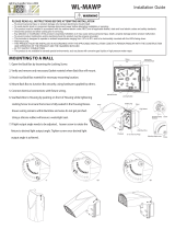
2.2.6 Dimensions Figure 1: L-804 Dimensions

© ADB bvba All Rights Reserved 7
2.2.7 Required Equipment Refer to Table 1 for required equipment that is supplied. Refer to Table 2 for required
equipment that is not supplied. Refer to the Parts section for part numbers.
Table 1: Required Equipment Supplied
Table 2: Required Equipment Not Supplied
Description Quantity
L-804 runway guard light. Includes lamps, frangible column, and 2-pin L-
823 cordset, or a 4-pin cordset, or a 5-pin cordset with matching harness.
1
Instruction manual 1 per order
Description Quantity
Level 1
L-867B light base plate (Part Number 1832RGL). This base plate must be
ordered as a separate item. Refer to the Warning below for using the L-
867B light base.
1
Wire, AWG 16 (minimum), 600 V−AWG 12 (maximum) 600 V As required
Ground wire, AWG 6, solid copper As required
Ground rods As required
Torque wrench As required
WARNING
Use only the L-867B heavy duty
light base supplied by ADB Airfield
Solutions.
Failure to observe this warning will
result in damage to the installed L-
804 RGL caused by high wind
loads.
See FAA specification AC
150/5345-46 wind loading
requirements.

L-804 Elevated Runway Guard Light
96A0218 Rev. X
Installation
© ADB bvba All Rights Reserved8
2.3 Installation Figure 2: L-804 Runway Guard Light
2.3.1 Introduction The L-804 runway guard light is an elevated light fixture consisting of two lamps mounted side
by side in the same housing that alternately flash 45-50 times per minute in yellow or red light
to identify taxiway holding position lines.
The light fixture is unidirectional and can be aimed in elevation vertically from 0 to +20
degrees, and horizontally ±20 degrees. The L-804 is manufactured in accordance with FAA
specification AC 150/5345-46 and the International Civil Aviation Organization (ICAO)
specification Annex 14.
This section provides instructions for installing the L-804 Runway Guard Light (RGL).
Refer to the airport project plans and specifications for the specific installation instructions.
2.3.2 Inspection on Arrival The equipment is shipped ready for installation. Handle equipment very carefully to prevent
component damage. Unpack the carton upon receipt and check the contents and their
condition. Note any exterior damage to the carton that might lead to detection of equipment
damage.
If you note any damage to any equipment, file a claim with the carrier immediately. The
carrier may need to inspect the equipment.
2.3.3 Installation
Procedures
L-804 RGLs are installed at a runway holding position to provide a distinctive warning to
anyone that they are about to enter an active runway. Normally the L-804 RGLs are installed
in pairs, one on either side of the taxiway. Refer to FAA Advisory Circular, AC 150/5340-30,
Design and Installation Details for Airport Visual Aids for dimensional location of the elevated
L-804 RGL.
The L-804 RGL is designed to be installed on an L-867B light base housing using an L-867B
heavy duty base plate that has been specifically designed per FAA specifications found in
FAA AC 150/5345-46B to withstand the high bending moments induced on the elevated
fixture.
NOTE: L-804 RGL shall not be stake mounted per FAA AC 150/5345-46.
The ADB Airfield Solutions mounting system includes a frangible column, L-823 cordset ,
L-867B special base plate, and tether assembly. See Figure 4.

© ADB bvba All Rights Reserved 9
2.3.4 Installing the L-867B
Base
To install the base, perform the following procedure:
1. Install the L-867B per the site plans and specifications. See FAA AC 150/5340-30 for
additional installation instructions.
2. Orient the cable entrance hubs of the base in the proper directions.
3. Level the light base so that the mounting flange surface is flush with the finished grade.
4. With the light base at proper orientation and held at proper elevation, pour concrete
around the outside of the base. If the base is installed outside the concrete pad, backfill
with compacted earth.
5. Slope top of concrete away from the flange portion of the base.
6. In closed duct systems installed in soil conditions of good drainage, use light bases
having a drain hole to prevent water accumulation.
7. Pull field cable and connect the L-830, if specified, in the light base.
8. Install the base plate w/gasket on top of the light base. The baseplate is designed to
receive the RGL frangible coupling using a female thread.
2.3.5 Installing on a L-867B
Base
To install the L-804, perform the following procedure:
1. If using the current driven L-804, install the L-804 RGL assembly and frangible column,
and connect the L-823 cordset supplied with the RGL to an L-830, 100 W/6.6 A isolation
transformer. See Figure 9 in the Wiring Schematics section for wiring connections for
current driven monitored and unmonitored versions.
If using the voltage driven L-804, install the L-804 RGL assembly and frangible column,
and connect the L-823 cordset supplied with the RGL to 120 or 220-240 Vac input. See
Figure 10 and Figure 11 in the Wiring Schematics section for wiring connections for
voltage driven monitored and unmonitored versions.
If using the Direct Lamp Access L-804, install the L-804 assembly and frangible column,
and connect the L-823 cordsets supplied with the RGL to the two BRITE outputs. The
connection order is not important. See Figure 12 in the Wiring Schematics section for
wiring connections for the Direct Lamp Access versions.
2. Bolt the base plate to the light base.
NOTE: Only use two of the mounting bolts at this time and only hand tighten these bolts.
After horizontal aiming has been completed and verified, install the remaining baseplate
bolts and then torque bolts to 180 – 190 In-Lbs.
3. Aim the L-804 RGL both vertically and horizontally per site plans and specifications.
Aiming procedure is as follows:

L-804 Elevated Runway Guard Light
96A0218 Rev. X
Installation
© ADB bvba All Rights Reserved10
2.3.5.1 Horizontal Aiming NOTE: See Figure 5 and “Installing Coupling (Unmonitored)” on page 14 or “Installing
Coupling (Monitored)” on page 14 before proceeding. Back out or remove the two hex head
set screws that are in the side of the baseplate hub so that the coupling can be screwed into
the hub.
Before screwing the coupling into the baseplate, use a black marker to put “tick mark” in line
with the slot and above the frangible groove as shown in the photo below. The tick-mark will
aid in locating the slot after the coupling is screwed into the baseplate hub
1. Apply anti-seize paste on threads and then screw the frangible coupling into the hub on
the baseplate until the frangible groove is just above the top edge of the hub.
Locate the set screw hole in the side of the hub that is nearest to the slot in the coupling by
locating the “Tic-mark.” Rotate the coupling, either clock or counter-clockwise, until the
“tick-mark” on the coupling is in line with the set screw hole in the hub.
NOTE: It is important to make sure that the slot and the set screw hole are aligned
because of the close fit between the slot and the ¼-20 screw. The close fit between the
screw and the slot prevents the coupling from turning and loosening when the face of the
RGL is subjected to jet engine exhaust or wind.
2. Thread the set screw into the hub and through the slot in the coupling. The screw must
pass through the slot so it does not tightened against the screw threads on the coupling.
Hand-tighten this screw only until final horizontal aiming has been completed.
2.3.5.2 Adjusting Horizontal
Setting
To adjust the horizontal setting, perform the following procedure:
1. 1. Thread the set screw into the hub and through the slot in the coupling. The screw must
pass through the slot so it does not tightened against the screw threads on the coupling.
Hand-tighten this screw only until final horizontal aiming has been completed.
2. See Figure 3 and photo below. Locate the four Phillips head screws – ref Item 8 in Fig 3
and loosed them so that the frangible coupling can be inserted into the hub. Also, if
necessary, loosen the two 3/8-16 allen hex head set screws in the RGL adjustable joint –
Ref Item 7 in Fig 3.
NOTE: The Zero (“0”) on the horizontal label that is affixed to the frangible coupling, has
been aligned at the factory with the index pin pressed into the lower hub of the adjustable
arm. This alignment will then allow the 10-32 screw to be screwed into the top center
Zero (“0”) hole and pass through the Zero (“0”) hole that is located at the top of the
coupling. See figures above.
Place “Tick-
Mark” Here
Zero (“0”) Screw Hole
Zero (“0”) Hole

© ADB bvba All Rights Reserved 11
3. Rotate RGL assembly until the indicator pin that is found at the bottom edge of the
adjustable arm hub is aligned with the desired angle. The horizontal angle label that is
affixed to the coupling is marked in 5 degree increments. See the following figure.
NOTE: The appropriate screw to tighten all the way into the mating hole in the frangible
coupling is determined by the degrees adjusted. For example, if the horizontal is adjusted to
20 degrees, the top screw marked 20, 0, 20 should go in all the way. Hand tighten all four
screws. See photos above.
Verify that the selected angle meets the requirements of the site plans and specifications.
If the horizontal aiming angle is not correct make one or both of the following
adjustments:
1. Remove the two screws in the side of the baseplate hub and rotate the coupling slot to
line up with the other tapped hole in the hub. Repeat horizontal aiming procedure above.
2. If additional adjustment is needed then remove the two mounting bolts used to fasten the
baseplate to the L868B light base. Rotate the baseplate either clock or counter-clock
wise at least 30 degrees. Repeat the horizontal aiming procedure above.
3. Once horizontal aiming is completed install and torque all mounting hardware that
secures the baseplate to the L867B light base.
2.3.5.3 Vertical Aiming To adjust the vertical setting, perform the following procedure:
1. See Figure 3. Loosen two Allen hex set screws on side shown in photo and on opposite
side.
2. Loosen hex bolt (6) on the face (side) of RGL.
3. Adjust the vertical setting to the desired number of degrees in one-degree increments by
lining up the indicator pin (9) from 0 to +20 degrees.
4. Tighten the hex bolt (6). Refer to Table 8.
5. Tighten the hex bolts (1). Refer to Table 8.
NOTE: See Figure 3 for additional installation instructions and bolt torque values. Refer
to Table 8.
6. After the RGL has been aimed and operation has been verified, install the tether by
attaching one end of the tether to one of the bolts on the center housing of the RGL and
attach the other end to nearest bolts securing the baseplate to the light base housing. 5..
NOTE: There are two set screws in the side of the hub. These set screws are used when
the RGL is being aimed horizontally.
Horizontal Angle
Label
Indicator Pin
Set Screw - 2 Places
180 Degrees Apart

L-804 Elevated Runway Guard Light
96A0218 Rev. X
Installation
© ADB bvba All Rights Reserved12
Figure 3: Bolt Torque Values
Table 3: Table 8. Bolt/Screw Torque Values
0
2
0
20
1020 10
0
20
26-in MAX
(660.4 mm)
20.00°
7 - Set Screw
9 - Indicator Pin for Vertical Setting
8 - Phillips
Head Screws
6 - Hex Bolts
2 - Set Screws
5 - Hex Bolts
4 - Hex Bolts
10 - Indicator Pin for Horizontal Setting
Item Number Number/Type Torque Values
2 2 set screws 140 in-lb
4 6 hex bolt 15 ft-lb
5 2 hex bolts 70 ft-lb
6 1 hex bolt 77 ft-lb
7 2 set screws 40 ft-lb
8 4 Phillips head screws Hand-tighten

© ADB bvba All Rights Reserved 13
Figure 4: L-804 Base Installation
1. L-804 Light Fixture 3. L-867B Light Base 5. Hex Set Screw
2. Special Heavy Duty Base Plate 4. Concrete
1-L-804 Light Fixture
2-Special Heavy
Duty Base Plate
3-L-867B Light Base
4-Concrete
5-Hex Set
Screw

L-804 Elevated Runway Guard Light
96A0218 Rev. X
Installation
© ADB bvba All Rights Reserved14
2.3.6 Installing Coupling
(Unmonitored)
This subsection describes how to install the coupling for the current and voltage driven
unmonitored versions of the RGL.
2.3.6.1 Current Driven
Unmonitored RGL
See Figure 9 in the Wiring Schematics section for the current driven unmonitored wiring
schematic. See Figure 5. To install the coupling for the current driven unmonitored version,
plug the L-830 transformer secondary cordset (2) into the 2-pin L-823 connector (1).
Figure 5: L-804 Coupling (Monitored and Unmonitored Versions)
2.3.6.2 Voltage Driven
Unmonitored RGL
See Figure 10 in the Wiring Schematics section for the 120 V and the 220-240 V voltage
driven unmonitored wiring schematics.
To install the coupling for the voltage driven unmonitored version, perform the following
procedure:
1. See Figure 5. Plug the 2-pin L-823 cable (1) into the L-823 receptacle (2).
2. Wire the free ends to the proper voltage source.
2.3.7 Installing Coupling
(Monitored)
This subsection describes how to install the coupling for the current and voltage driven
monitored versions of the RGL.
2.3.7.1 Current Driven
Monitored RGL
See Figure 9 in the Wiring Schematics section for the current driven monitored wiring
schematic.
To install the coupling for the current driven monitored version RGL, perform the following
procedure:
1. See Figure 5. Plug the 5-pin cordset cable (3) into the 5-pin harness (4).
2. Wire the monitor leads (orange, red, and green) to the monitor circuit.
2.3.7.2 Voltage Driven
Monitored RGL
See Figure 11 in the Wiring Schematics section for the 120 V and the 220-240 V voltage
driven monitored wiring schematics.
To install the coupling for the voltage driven monitored version RGL, perform the following
procedure:
1. See Figure 5. Plug the 5-pin cordset cable (3) into the 5-pin harness (4).
2. Connect the black and white wires to the proper voltage source.
3. Wire the monitor leads (orange, red, and green) to the monitor circuit.
Unmonitored Version
Monitored Version
1 L-823 Cordset (2-Pin)
3 L-823 Cordset (2-, 4-,or 5-Pin)
2 L-830 Secondary Cordset
(Shown) or L-823 Direct Lamp
Access Harness (Provided)
4Wiring Harness
(2-, 4-, or 5-Pin) (Provided)
/