Page is loading ...

WTI Part No. 14506
Rev. G
Internal Cellular Modem
Set Up Guide

1-1
1. Introduction
This Quick Start Guide provides a basic overview of the procedure for installing and
setting up WTI’s Cellular Modem option on WTI Devices.
Notes:
• Although both the Command Line Interface (CLI) and Web Browser Interface
can be used to adjust cellular parameters once cellular communication has
been set up, the CLI includes vital configuration functions that are not present
in the Web Browser Interface. For this reason, the CLI is used when setting
up the Cellular Modem Option.
• Prior to setting up the Cellular Modem Option, it is recommended to install
and configure your WTI Device as described in the Hardware Guide.
• When accessing the WTI Device’s Command Mode, please refer to the
WTI User’s guide for further instructions.
https://www.wti.com/blogs/knowledge-base/basic-info-for-setting-up-
the-cell-interface

2-1
2. Installation
In order to communicate with your WTI Device via the Cellular Modem Option, you will
first need to purchase a cellular plan.
When choosing a cellular plan, WTI recommends that the plan should provide the
following:
• A Static IP Address is recommended, but not required. If you need to use a
Dynamic IP Address, then a DDNS provider will be required.
• A VPN (Virtual Private Network)
• An IOT/M2M Data Plan
• An APN (Access Point Name) to establish an active PPP session.
• A 2FF SIM Card
• Mobile terminated data
• When configuring your network, SSH port 22 and HTTPS port 443 should
both be Open.
2.1. Attach the Cellular Antennae
Attach the two Cellular Antennae, (included with the unit,) to the two threaded
connectors on the WTI Device's face plate.

2-2
Installation
2.2. Installing the SIM Card
Once you have purchased a cellular plan, the next step is to install the SIM card,
(provided with your cellular plan,) in your WTI Device. To install the mini SIM card,
proceed as follows:
Notes:
• The SIM Card slot is designed to accept a form factor 2FF SIM Card .
• Prior to installing the SIM Card, make certain that the WTI Device is
powered Off.
* If rack brackets have been installed on the WTI device, it will be necessary to
remove the rack brackets in order to expose the SIM Card cover panel.
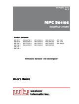
1. Remove the SIM Card cover panel on the left hand side of the WTI unit, located
adjacent to the cellular antenna as shown in Figure 2.1 below. Note that the panel
is held in place by a small Phillips Head screw.
2. Carefully slide the SIM card into the SIM Card Slot with the keyed/notched corner
of the card facing towards the unit’s faceplate (see diagram on cover plate.) Make
certain the SIM Card is firmly seated, but do not apply excess pressure that might
damage the card.
3. Replace the panel that covers the SIM Card Slot, reinstall the retaining screw and
restore power to the WTI Device.
Figure 2.1: The SIM Card Cover Panel

3-1
3. Setup and Configuration
After the cellular antennae and SIM Card have been installed, the next steps are to
configure the SIM Card and define the Static Route.
Notes:
• Although both the Command Line Interface (CLI) and Web Browser Interface
can be used to adjust cellular parameters once cellular communication has
been set up, the CLI includes vital configuration functions that are not present
in the Web Browser Interface. For this reason, the CLI is used when setting
up the Cellular Modem Option.
• Prior to setting up the Cellular Modem Option, it is recommended to install
and configure your WTI Device as described in the Hardware Guide.
• When accessing the WTI Device’s Command Mode, please refer to the
WTI User’s guide for further instructions.
https://www.wti.com/blogs/knowledge-base/basic-info-for-setting-up-
the-cell-interface

3-2
Setup and Configuration
3.1. Configuring the SIM Card
After installing the SIM Card, use the /cell command to configure the SIM Card as
described below:
1. Access the Text Interface Command Mode for the WTI Device via Console Port or
Network Port.
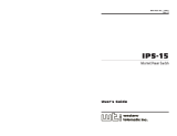
2. When the command prompt appears, type /cell and press [Enter] to display the
Cell Modem Statistics menu as shown in Figure 3.1 above.
3. At the Cell Modem Statistics menu, select “APN, Carrier.”
4. At the Access Point Name configuration menu, use the Access Point Name (APN)
option to key in the APN, (supplied with your cellular plan,) and press [Enter]. Use
the Carrier option to select the service provider (carrier) that the REM will use. The
Cellular Modem Option will be automatically configured, based on the information
on the SIM Card.
5. The configuration procedure may take several minutes. When configuration
is complete, Cell Modem Statistics menu will be redisplayed, indicating that
configuration was successful.
Figure 3.1: The Cell Modem Statistics Menu (Example Values Shown)
CELL MODEM STATISTICS: Vendor: Multitech Model: MTSMC-LVW2
Desc: 4G/LTE Rev: 17.01.571
CELL MODEM INFORMATION
Cell Phone Number: (undened)
Device ID (IMEI): 202102110000000
SIM Number (ICCID): (undened)
Cell Network Carrier: (undened), (undened)
Signal Quality (0-31): 26 (Excellent)
Cell Session Established: No
CELL MODEM CONFIGURATION
1. Cell Modem Parameters
2. APN, Carrier: apn.carriername
3. Public IP Address: 111.222.333.444
4. Wakeup on Failure: Disabled
5. IP Passthrough: Disabled
6. Refresh Parameters
Enter: #<CR> to change, <ESC> to exit ...

3-3
Setup and Configuration
3.2. Defining the Static Route
After the SIM Card has been installed and configured, the next step is to define the
Static Route.
Note: The Static Route is only required if the Cell Modem Port is not defined
as the default gateway.
3.2.1. Defining Static Route when the Default Gateway
Address is Known
If you already know the default gateway address for your cellular network, then
proceed as follows. If you don't know the default gateway address, please proceed to
Section 3.2.2.
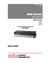
1. Type /p modem and press [Enter] to display the Cell Modem Parameters menu as
shown in Figure 3.2 below..
2. When the Cell Modem Parameters menu is displayed, select Static Route to display
the Static Route submenu. When the Static Route submenu is displayed, key in a
number for the first vacant Static Route definition line and press [Enter].
3. Define the Static Route using the following format:
route add GGG.GGG.GGG.GGG gw CCC.CCC.CCC.CCC
Where:
GGG.GGG.GGG.GGG is the default Gateway Address
CCC.CCC.CCC.CCC is the IP Address for the Cell Modem.
4. Press [Esc] once to exit the Static Route menu, then press [Esc] again to exit the
Cell Modem Parameters menu and save the newly defined Static Route. Note that it
may require several minutes for the Cell Modem to save newly defined parameters.
5. Perform the verification procedure described in Section 5 to make certain that
cellular access has been properly enabled.
Figure 3.2: The Cell Modem Parameters Menu
CELL MODEM PARAMETERS: [cell] IPv4
COMMUNICATION SETTING SERVERS AND CLIENTS
1. Default Gateway: O 21. Web Access: On
2. User Peer DNS: O 22. SNMP Access: O
3. Static Route: O 23. PING Access: Allow
4. DDNS Services: (undened)
5. Modem Stay Alive: O
6. LCP Echo: On
7. Protocol: IPV4
8. MTU/MRU: 552
9. Modem PPP Params:
Enter: #<CR> to change,
<ESC> to exit and save conguration ...

3-4
Setup and Configuration
3.2.2. Defining Static Route when the Default Gateway Address
is Unknown
If you don't know the default gateway address used by the cellular network, then you will
need to use the WTI Device's /bash command to display the default gateway address
as described below:
1. If you are communicating via local network and do not require the default gateway
address, log into the WTI Device via serial port, USB or network (if your network is
on the same network and doesn’t require the default gateway.)
2. Temporarily Disable Default Gateway for the Network Port: When the command
prompt appears, type /N and press [Enter] to display the Network Parameters
menu as shown in Figure 3.3 below.
a) At the Network Parameters menu, select Gateway Address. The Gateway
Address submenu will be displayed. Record the currently defined Gateway
Address.
Note: Make certain to write down or save the currently defined Gateway
Address; you will need this address later, when you re-enable the Default
Gateway at the Network port after Static Route definition is complete.
b) At the Gateway Address submenu, press the [Space] bar and then press
[Enter]. This will delete the currently defined Gateway Address, disabling the
Default Gateway at the Network Port.
c) Press [Esc] twice to exit the Network Parameters menu and save changed
parameters.
Figure 3.3: The Network Parameters Menu
NETWORK PARAMETERS: [eth0] IPv4
COMMUNICATION SETTING SERVERS AND CLIENTS
1. IP Address: 192.168.100.25 21. Telnet Access: On
2. Subnet Mask: 255.255.255.0 22. SSH Access: On
3. Gateway Addr: 192.168.100.2 23. Web Access: On
4. DHCP: O 24. SYSLOG
5. IP Tables: O 25. SNMP Access: On
6. Static Route: O 26. SNMP Trap: O
7. DNS Services: (undened) 27. LDAP: O
8. Negotiation: Auto 28. TACACS: O
9. Fallback: O 29. RADIUS: O
30. PING Access: Allow
GENERAL PARAMETERS 31. Multiple Logins: On
11. Admin Mode: Permit 32. Email Messaging: O
12. Logo Char: ^X 33. Outbound Access: O
13. Sequence Disc: One Char 34. Raw Socket Access: O
14. Inact Timeout: O
15. Command Echo: On
16. Accept Break: On (ASCII 28)
Enter: #<CR> to change,
<ESC> to exit and save conguration ...

3-5
Setup and Configuration
3. Enable the Default Gateway for the Cell Modem Port: At the Text Interface
command prompt, type /p modem and then press [Enter] to display the Cell
Modem Parameters menu.
a) When the Cell Modem Parameters menu is displayed, select Default Gateway.
Use the resulting menu to enable the Default Gateway for the Cell Modem Port.
b) Press [Esc] twice to exit the Default Gateway menu and save newly defined
parameters.
Note: It may require several minutes for the Cell Modem to save the newly
defined Default Gateway status.
4. Display the IP Address for the Cell Modem Port:
a) At the WTI Device command prompt, type /cell and press [Enter] to display
the Cell Modem Statistics menu.
b) When the Cell Modem Statistics menu is displayed, write down the IP Address
for the Cell Modem Port (listed under the Cell Connection Information heading.)
c) Press [Esc] to exit from the Cell Modem Statistics menu.
5. Establish an SSH connection to the WTI Device via the cellular network.
6. Display the Gateway Address: At the WTI Device command prompt, type
/bash netstat -nat and press [Enter] to display the Active Internet
Connections screen, shown in Figure 3.4 below. Note that it may take several
minutes for the unit to respond.
a) The Cell Modem Port IP Address with be displayed in the “Foreign Address”
column.
b) The “State” column for the Cell Modem Port IP address will read “Established.”
c) Note the Gateway Address (Local Address,) that corresponds with the Cell
Modem Port IP address (Foreign Address.)
d) To exit from the Active Internet Connections menu, press [Enter].
Figure 3.4: Active Internet Connections Screen
Active Internet connections (servers and established)
Proto Recv-Q Send-Q Local Address Foreign Address State
tcp 0 0 192.168.100.25:443 0.0.0.0:* LISTEN
tcp 0 0 192.168.100.25:80 0.0.0.0:* LISTEN
tcp 0 0 0.0.0.0:22 0.0.0.0:* LISTEN
tcp 0 0 192.168.100.25:22 192.168.200.23:64430 ESTABLISHED
tcp 0 0 :::22 :::* LISTEN
tcp 0 0 :::23 :::* LISTEN

3-6
Setup and Configuration
7. Define the Static Route: At the WTI Device command prompt, type /p modem
and press [Enter] to display the Cell Modem Parameters menu as shown in
Figure 3.1.
a) When the Cell Modem Parameters menu is displayed, select Static Route
to access the Static Route submenu. When the Static Route submenu is
displayed, key in a number for the first vacant Static Route definition line and
press [Enter].
b) At the Static Route menu, refer to the Cell Modem Port Address (Foreign
Address) and Gateway Address (Local Address) that were determined above.
Enter a route command using the following format:
route add GGG.GGG.GGG.GGG gw CCC.CCC.CCC.CCC
Where:
GGG.GGG.GGG.GGG is the Gateway Address (Local Address)
CCC.CCC.CCC.CCC is the Cell Modem Address (Foreign Address)
c) Press [Enter] to select the newly defined Static Route, then press [Esc] twice
to save the Static Route definition and exit the Static Route menu. Note that it
will require several minutes for newly defined parameters to be saved.
d) For more information, please refer to the example on the next page.

3-7
Setup and Configuration
Static Route Definition Example:
Assume that the address for the Cell Modem Port address (Foreign Address) is
CCC.CCC.CCC.CCC and the netstat function returns the Active Internet Connections
screen shown in Figure 3.5 above. In this example, the Gateway Address (Local
Address) would be GGG.GGG.GGG.GGG. Therefore, the static route would be defined as
follows:
route add GGG.GGG.GGG.GGG gw CCC.CCC.CCC.CCC
1. Disable the Default Gateway for the Cell Modem Port:
a) At the WTI Device command prompt, type /p modem and press [Enter] to
display the Cell Modem Parameters menu.
b) When the Cell Modem Parameters menu is displayed, access the Default
Gateway submenu and disable the Default Gateway for the Cell Modem Port.
c) Press [Esc] twice to exit from the Cell Modem Parameters and save the newly
defined Default Gateway Status.
Note: It may require several minutes for the Cell Modem to save the newly
defined parameters.
2. Re-Enable the Default Gateway for the Network Port: When the command
prompt appears, type /N and press [Enter] to display the Network Parameters
menu.
a) At the Network Parameters menu, select Gateway Address. The Gateway
Address submenu will be displayed.
b) At the Gateway Address submenu, key in the previous Gateway Address that
you saved in Step 2 at the beginning of this section and then press [Enter].
c) Press [Esc] twice to exit the Network Parameters menu and save changed
parameters.
Note: It may require several minutes for the Cell Modem to save the newly
defined parameters.
Figure 3.5: Static Route Denition Example
Active Internet connections (servers and established)
Proto Recv-Q Send-Q Local Address Foreign Address State
tcp 0 0 0.0.0:22 0.0.0.0:* LISTEN
tcp 0 0 GGG.GGG.GGG.GGG:22 CCC.CCC.CCC.CCC:2892 ESTABLISHED
tcp 0 0 :::22 :::* LISTEN

4-1
4. Enable Web Access
If you need to allow access to the WTI Device's web browser interface via cellular, you
must enable Web Services via the Cell Modem Parameters menu.
1. At the WTI Device command prompt, type /p modem and press [Enter] to display
the Cell Modem Parameters menu (Figure 3.1).
2. When the Cell Modem Parameters menu appears, select Web Access and then use
the resulting submenu to enable Web access via cellular.
3. Press [Esc] twice to exit from the Cell Modem Parameters menu and save the
newly defined Web Services status.
Note: It may require several minutes for the Cell Modem to save the newly
defined Web Access status.

5-1
5. Verify that Cellular Access is Available
After setting up Cellular Access, it is recommended to perform this procedure to verify
that the procedure was completed successfully.
1. If you are still connected to the WTI Device command mode, type /X and press
[Enter] to disconnect from the unit.
2. Verify Cellular Access to Text Interface (CLI):
a) Create an SSH connection to the WTI Device via cell. When the login prompt
is displayed, enter your username and password. When the command prompt
appears, type /cell and press [Enter].
b) If the Cell Modem Statistics screen appears, this indicates that cellular network
access has been successfully enabled.
c) If the Cell Modem Statistics screen fails to appear after several minutes, this
probably means that there is an error in the definition of the Static Route. In
this case, use the procedure described in Section 3 to display the Static Route
definition. Carefully check the Static Route definition to make sure that the IP
addresses were entered correctly and that there are no syntax errors.
3. Verify Cellular Access to Web Browser Interface:
a) Start your Web Browser, key the Cell Modem Port IP Address for the
WTI Device into the browser’s address bar. When the login prompt is
displayed, key in your username and password.
b) If the WTI Device’s home page is displayed, this means that cellular access to
the WTI Device has been successfully enabled.
c) If the WTI Device’s home page is not displayed, this probably means that either
Web Access has not been enabled as described in Section 4 or there is an
error in the Static Route definition.
i. Web Access Not Enabled: Make certain that web access has been
enabled as described in Section 4.
ii. Static Route Error: Use the procedure described in Section 3 to display
the Static Route definition. Carefully check the Static Route definition to
make sure that the IP address were entered correctly and that there are no
syntax errors.

6-1
6. Setting Up the Firewall/IP Tables (Optional)
If you wish to restrict access to the WTI Device via cellular, you must define a firewall.
The IP Tables menu is used to define a firewall which determines which IP addresses will
be allowed to access the WTI Device via cellular and which IP addresses will be denied.
To define the firewall, proceed as follows:
1. At the Text Interface command prompt, type /N and press [Enter] to display the
Shared (eth0) Network Parameters menu.
2. When the Network Parameters menu is displayed, select the IP Tables option.
3. When the IP Tables menu is displayed, use Linux syntax to determine which IP
address(es) will be allowed access and which IP address(es) will be denied. In
most cases, the IP Tables should allow access to administrators and deny access to
everybody else.
This completes the set-up procedure for the WTI Cellular Modem Option. For further
information, please refer to the WTI User Guide and the following article in the WTI
Knowledge Base:
https://www.wti.com/blogs/knowledge-base/basic-info-for-setting-up-the-cell-
interface

western
telematic
inc.
TM
5 Sterling • Irvine • California 92618
(949) 586-9950 • Toll Free: 1-800-854-7226
Fax: (949) 583-9514 • https://www.wti.com
/