Page is loading ...

MAN034 Rev Date 10/7/2004
VOPEX-USBV-2
USB Keyboard, Video, and Mouse
Splitter/Hub
Installation and Operation Manual
V
OPEX
TM
Series
NETWORK
TECHNOLOGIES
INCORPORATED
Tel:330-562-7070
Fax:330-562-1999
1275 Danner Dr
Aurora, OH 44202
www.nti1.com
NTI
R

MAN034 Rev Date 10/7/2004
Warranty Information
The warranty period on this product (parts and labor) is one (1) year from the date of purchase. Please contact Network
Technologies Inc at (800) 742-8324 (800-RGB-TECH) or (330) 562-7070 or visit our website at http://www.nti1.com for
information regarding repairs and/or returns. A return authorization number is required for all repairs/returns.
COPYRIGHT
Copyright © 2004 by Network Technologies Inc. All rights reserved. No part of this publication may be reproduced, stored in a
retrieval system, or transmitted, in any form or by any means, electronic, mechanical, photocopying, recording, or otherwise,
without the prior written consent of Network Technologies Inc, 1275 Danner Drive, Aurora, Ohio 44202.
CHANGES
The material in this guide is for information only and is subject to change without notice. Network Technologies Inc reserves the
right to make changes in the product design without reservation and without notification to its users.
Trademark
---- VOPEX is a trademark of Network Technologies Inc in the U.S. and other countries.

MAN034 Rev Date 10/7/2004
TABLE OF CONTENTS
INTRODUCTION.............................................................................................................................................................1
LIMITATIONS..................................................................................................................................................................1
MATERIALS....................................................................................................................................................................1
FEATURES AND FUNCTIONS.......................................................................................................................................2
INSTALLATION...............................................................................................................................................................3
Monitor Connection......................................................................................................................................................3
Mouse Connection.......................................................................................................................................................3
Keyboard Connection..................................................................................................................................................3
CPU Connection..........................................................................................................................................................4
Hub Ports.....................................................................................................................................................................4
Power-Up.....................................................................................................................................................................4
OPERATION ...................................................................................................................................................................5
Keyboard Command Mode..........................................................................................................................................5
Mice and Trackballs with MACs ..................................................................................................................................6
International SUN Keyboards......................................................................................................................................6
Hub Ports.....................................................................................................................................................................6
SPECIFICATIONS ..........................................................................................................................................................7
TROUBLESHOOTING....................................................................................................................................................7
TABLE OF FIGURES
Figure 1- Connect User 1 Keyboard, Mouse, and Monitor.................................................................................................................3
Figure 2- Connect the VOPEX to the CPU ........................................................................................................................................4
Figure 3- Connect other devices to Ports 2-4 ....................................................................................................................................4

NTI BRANDNAME AND DESCRIPTON
1
INTRODUCTION
The VOPEX-USBV-2-HUB (VOPEX) is a USB KVM Splitter and 3-Port Hub. It enables the control of one USB enabled CPU
through two separate USB keyboards, USB mice, and VGA monitors and it enables the connection of 3 additional USB devices
(other than keyboards or mice). Each user is able to have complete control of a CPU, provided they don't try to access it at the
same time. While the user access is controlled by four (4) separate modes of operation, both user monitors will show the same
image at all times. The 3 hub ports (for printer, scanner, camera, etc.) will be connected to the CPU at all times.
Types of User Input Devices Supported:
• USB keyboard with Windows layout
• USB keyboard with SUN layout
• USB keyboard with MAC layout
• USB Mouse - (up to 3 buttons)
• USB IntelliMouse (scrollwheel)
• Mouse-Trak trackball
• Logitech, Kensington and Microsoft Wheelmouse or Trackball on Mac CPUs with special drivers
• Logitech Cordless Elite Duo keyboard and mouse
• Crystal Vision keyboard with touchpad
• Gyration keyboard/mouse
• NTI USB-PS/2 Adapter
• NTI USB-SUN Adapter
Types of Shared Devices Supported:
• Both low-speed and full speed USB devices are supported.
• USB 1.1 compliant.
• Plug-n-Play specification supported
Types of CPUs Supported:
Any USB CPU supporting USB version 1.0 or above including:
• USB WINxx
• USB MAC
• USB SUN
LIMITATIONS
• The USB ports on the VOPEX are USB 1.1 compatible. Any USB 2.0 device connected to the VOPEX will be regulated to
USB 1.1 speeds.
MATERIALS
Materials included with this kit:
• VOPEX-USBV-2 2-Port USB KVM Splitter
• USB-AB-1M-ST 1 Meter Transparent USB A-B Device Cable
• VEXT-3 3' M-F VGA Video Cable
• 120 or 240VAC @ 50 or 60Hz-5VDC/2.0A AC Adapter

NTI BRANDNAME AND DESCRIPTON
2
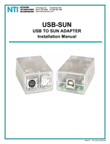
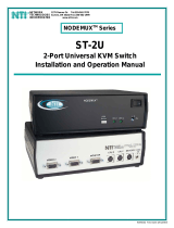
FEATURES AND FUNCTIONS
1. Power Switch- to power up or power down the VOPEX-USBV-2.
2. Power LED- for visual indication of splitter's power status
3. Mode Status LEDs- for visual indication of splitter's operating mode
4. Mode Switch- press to manually switch between operating modes
5. VIDEO- 15HD male connector- for connecting the video cable from the CPU
6. MONITOR x- 15HD female connectors- for connection of the user video monitors
7. 5VDC- connection jack for the AC adapter
8. DEVICES x- USB type A female connectors- for connection of the cables from USB devices
9. USER x DEVICES- USB type A female connectors- for connection of user USB device(s)
10. CPU- USB type B female connector- for connection of the devices cable from the CPU
6
10
7
5
8
VOPEX
U1
3
2
1
4
Front View of VOPEX-USBV-2
Rear View of VOPEX-USBV-2
NTI
R
Network Technologies Inc
5VDC
2A
-
+
CPU
USER 1
DEVICES
MONITOR 1
VIDEO
USER 2
DEVICES
NTI
Tel:330 -562- 7070
Fax:330-562-1999
1275 Danner Dr
Aurora, OH 44202
www.n ti1.com
MONITOR 2
U2 PwrMode
9
DEVICE 3 DEVICE 2 DEVICE 1
HUB PORTS

NTI BRANDNAME AND DESCRIPTON
3
INSTALLATION
FYI: It is not necessary to disconnect power to the CPU and monitor(s) before installation.
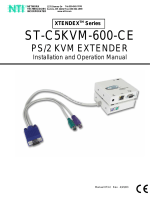
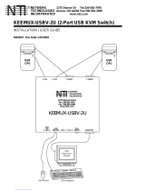
Monitor Connection
1.
Disconnect the monitor cable at the CPU and reconnect it to the "MONITOR 1" port on the VOPEX. (See Fig. 1)
2.
Plug a second monitor (or optional VEXT-xx extension cable) into the "MONITOR 2" port on the VOPEX.
Note: "xx" in VEXT-xx indicates the length of the cable in feet. Many lengths are available. Contact your VPI
salesperson or visit us at our website at http://www.vpi.us for details.
Mouse Connection
1.
Disconnect the mouse at the CPU and reconnect it to one of the female USB type A 'USER 1 DEVICES" ports on the
VOPEX.
2.
Connect a second mouse (or optional USB extension cable NTI USB-A+A-5M) to the female USB type A "USER 2 DEVICES"
ports on the VOPEX.
Keyboard Connection
1. Disconnect the keyboard at the CPU and reconnect the keyboard to the remaining female USB type A "USER 1 DEVICES"
port on the VOPEX.
2. Connect a second keyboard (or optional USB extension cable NTI USB-A+A-5M) to the remaining female USB type A "USER
2 DEVICES" ports on the VOPEX.
Figure 1- Connect User 1 Keyboard, Mouse, and Monitor
Rear View of VOPEX-USBV-2
5VDC
2A
-
+
CPU
USER 1
DEVICES
MONITOR 1
VIDEO
USER 2
DEVICES
NTI
Tel:330-562-7070
Fax:330-562-1999
1275 Danner Dr
Aurora, OH 44202
www.n ti1.com
MONITOR 2
DEVICE 3 DEVICE 2 DEVICE 1
HUB PORTS
15HD Female
Video Connector
USB KEYBOARD
USB MOUSE
USB Type A Female
USB Type A Male
VGA
Multi-Scan
Monitor
15HD Male
Video Connector
MONITOR 1

NTI BRANDNAME AND DESCRIPTON
4
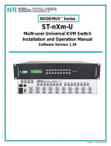
CPU Connection
1.
Connect the male USB type A connector end of the USB-AB-1M-ST cable into the device port on the CPU.
2.
Connect the male USB type B connector of the same cable to the "CPU" port on the VOPEX.
3.
Connect the male 15HD connector end of the VEXT-3 into the CPU’s video port. (See Fig. 2)
4.
Connect the female 15HD connector end of the VEXT-3 into the "VIDEO" port on the VOPEX.
Figure 2- Connect the VOPEX to the CPU
Hub Ports
If desired, connect additional USB devices to
the each of the three "Hub Ports" . These ports
will be powered and operate anytime the VOPEX
and CPU are powered ON. See Fig. 3.
Power-Up
If not already ON, turn ON power to the CPU
monitors, and VOPEX.
Figure 3- Connect other devices to Ports 2-4
Rear View of VOPEX-USBV-2
5VDC
2A
-
+
CPU
USER 1
DEVICES
MONITOR 1
VIDEO
USER 2
DEVICES
NTI
Tel:330-562-7070
Fax:330-562-1999
1275 Danner Dr
Auro ra, O H 4420 2
www.nti1.com
MONITOR 2
DEVICE 3 DEVICE 2 DEVICE 1
HUB PORTS
Scanner
AC
Adapter
ADAPTER
Printer
USB Camera
15HD Male
Video Connector
15HD Female
Video Connector
Rear View of VOPEX-USBV-2
5VDC
2A
-
+
CPU
USER 1
DEVICES
MONITOR 1
VIDEO
USER 2
DEVICES
NTI
Tel:3 30-562-7070
Fax:330-562-1999
1275 Danner Dr
Aurora, OH 44202
www.nti1.com
MONITOR 2
DEVICE 3 DEVICE 2 DEVICE 1
HUB PORTS
USB Type B
Female Connector
USB Type A Female
USB Type A Male
VEXT-3
15HD Male
Video Connector
USB Type B
Male
15HD Female
Video Connector
Rear View of Windows USB CPU
Video Port
Input Device Port
VIDEO
USB-AB-1M

NTI BRANDNAME AND DESCRIPTON
5
OPERATION
Mode Selection
The VOPEX comes equipped with four (4) modes of operation. To manually toggle between modes, depress the MODE button
once each time a mode change is desired. The VOPEX will cycle through the 4 modes of operation, then return to the first mode
(1 to 2, 2 to 3, 3 to 4, 4 to 1). The following table depicts the 4 operations available for operation.
MODE DESCRIPTION INDICATOR LEDS
1- INSTANTANEOUS Same as "DELAY" mode except that the delay is
only 2 seconds rather than 5.
2- DELAY First user with active device gets control of CPU.
Second user is "Locked out" until after 5 seconds
of no activity from first user.
3- USER 1 "USER 1" has sole access. "USER 2" is locked
out.
4- USER 2 "USER 2" has sole access. "USER 1" is locked
out.
Keyboard Command Mode
In order to control the other features of the VOPEX with the keyboard, Command Mode must be enabled. To enter
Command Mode from the keyboard:
Press
When the Command Mode is enabled, all 3 status lights on the keyboard will illuminate and both LEDs on the VOPEX will
illuminate solid to indicate Command Mode is enabled. See the table below for available functions while in Command Mode.
NOTE: The user must exit Command Mode in order to use the CPU in the selected mode. To exit Command Mode,
press ESC on the keyboard. ) The mouse will not operate while in Command Mode.
NOTE: While in Command Mode, when a proper programming key is pressed and recognized by the switch, the LEDs
on the keyboard will flash once to indicate acceptance. The user must exit Command Mode (by pressing ESC) to see a
change take effect in the switch operation.
NOTE: The VOPEX will automatically exit Command Mode after 10 seconds of inactivity by the user if the user does not
manually exit Command Mode.
The following functions exist while in Command Mode:
Key Combination Description of Function
<X>-<key>-<Y> Select a new key sequence to use to enter Command Mode- Replace <key> with the desired key
to follow <Ctrl> with.
<L> - <x> - <x> Select the country code of the keyboard being used with a USB SUN CPU (see Country Codes
chart on page 6)
<V> - <Enter> This will print the version of the code in the VOPEX to a text editor window (i.e. Windows Notepad)
for use when troubleshooting the VOPEX. Note: The text editor should be open prior to entering
Command Mode.
<M> Configure the CPU port to connect to a MAC CPU (see "Mice and Trackballs with MACs" on pg. 6.
<W> Configure the CPU port to connect to a Windows or SUN CPU
<D> - <x> Select the operating mode, x=1 for Instantaneous Mode, x=2 for Delay Mode, x=3 User 1Mode, x=4
for User 2 mode. (Modes are described in the table above.)
<P> - <x> Select the default mode to have the VOPEX enter upon power-up.
<Esc> Exit Command Mode
`
+
Ctrl
~
(ACCENT
KEY)
`
U1
U2
U1 U2
U1
U2
U1
U2

NTI BRANDNAME AND DESCRIPTON
6
Mice and Trackballs with MACs
The VOPEX can be configured to enable full functionality between mice and trackballs having two or more buttons and a USB
MAC CPU. By default, the CPU port on the VOPEX is configured for use a WINDOWS or SUN CPU and has no special
translation for using multi-function mice and trackballs when a MAC CPU is connected. Using the commands in Command Mode
above, either enable or disable this feature as needed.
NOTE: Be sure to re-configure port for connection to a WINDOWS or SUN CPU if a MAC CPU is removed and a
WINDOWS or SUN CPU is then connected.
International SUN Keyboards
The VOPEX can recognize international layouts for Sun keyboards. In order to use an international Sun keyboard, follow this
procedure:
1. Disconnect the CPU from the VOPEX
2. Connect the international keyboard to be used to the VOPEX
3. Power down the VOPEX for at least 3 seconds
4. Power up the VOPEX
5. Reconnect the CPU to the VOPEX
It is also possible to configure the VOPEX to emulate a specific international Sun keyboard regardless of what actual keyboard is
connected. This is recommended when the CPU needs the layout code (i.e. a SUN CPU) and the keyboard doesn't have an
explicit layout code (i.e. some Windows keyboards). To do this, manually set the VOPEX to indicate the international keyboard
identification number to the CPU using the following procedure;
1. Connect the keyboard to be used to the VOPEX
2. Power down the VOPEX for at least 3 seconds
3. Power up the VOPEX
4. Enter Command Mode (<Ctrl> - <`>)
5. Type Lxx, where xx is the number from the list below that corresponds to the desired country code
6. Exit Command Mode
7. Power down the VOPEX for at least 3 seconds
8. Power up the VOPEX
9. Reboot the CPU connected to the VOPEX
Country Codes
00 Not Supported 18 Netherlands/Dutch
01 Arabic 19 Norwegian
02 Belgian 20 Persian (Farsi)
03 Canadian-Bilingual 21 Poland
04 Canadian-French 22 Portuguese
05 Czech Republic 23 Russia
06 Danish 24 Slovakia
07 Finnish 25 Spanish
08 French 26 Swedish
09 German 27 Swiss/French
10 Greek 28 Swiss/German
11 Hebrew 29 Switzerland
12 Hungary 30 Taiwan
13 International (ISO) 31 Turkish
14 Italian 32 UK
15 Japan (Katakana) 33 US
16 Korean 34 Yugoslavia
17 Latin American 35-99 Reserved
Hub Ports
The three connections labeled "Hub Ports" can be used to connect any USB device, such as a printer, scanner,
camera, etc. for continuous operation at USB 1.1 compliant speeds. These ports are not controlled by the VOPEX.

NTI BRANDNAME AND DESCRIPTON
7
SPECIFICATIONS
Size: Each unit is 8.5”W x 6”D x 2.6”H
Power: Powered by 120 or 240VAC @ 50 or 60Hz-5VDC/2.0A AC Adapter
Connections: 15HD VGA & SGA compatible
USB Type A female device connectors
USB Type B female CPU connector
TROUBLESHOOTING
PROBLEM SOLUTION
• Keyboard error • Check cable connections on CPU and VOPEX
• Mouse not working • Check cable connections on CPU and VOPEX
• Monochrome on VIDEO OUT 1 port • No ID bits – call VPI immediately
MODEL NO: VOPEX-USBV-2
SERIAL NO: _____________________
DATE: _____________________
INSPECTED BY: ________________
Man034 Rev 10/7/04
/