Page is loading ...

1
IMPORTANT:
Go to www.extron.com for the complete
user guide, installation instructions, and
specifications bef
ore connecting the
product to the power source.
MPS602 Series • Setup Guide
This guide provides basic instructions for an experienced technician to install, set up, and operate the Extron Media Presentation
Switcher, MPS602. Installation and service must be performed by authorized personnel only. For additional information and
specications, see the MPS602 product page at www.extron.com.
The MPS 602 is available in three models. The MPS 602 is a non‑amplied model with a variable preamp output. The MPS 602
SA delivers stereo power amplication with 50 watts rms per channel into 4 ohms and 25 watts rms per channel into 8 ohms. The
MPS 602 MA provides mono 70 volt line amplication with 100 watts rms output.
Step 1 — Disconnect Power and Mount the MPS602
Disconnect power to the MPS602 and turn off all devices that will be connected to it. The MPS602 is housed in a full rack width,
8.5 inch deep, 1U high metal enclosure that can sit on a table with the provided rubber feet or rack mounted. Select a suitable
mounting location, choose an appropriate mounting option, and follow the instructions provided with the mounting kit.
Step 2 — Cable the Switcher
L
R
SIG LINK
DTP IN
SIG LINK
DTP OUT
50/60 Hz
100-240V 1.0A MAX
1
2
RGB OUT
HDMI
MIC
MIX
RS-232
MPS 602 SA
Tx Rx G
MUTE HDMI AUDIO
PHANTOM POWER
SELECT
3
4
5
6
OUTPUTS
AMP OUT REMOTE
OVER DTP
OVER DTP
RS-232 IR
Rx GTx Tx Rx
RS-232 IR
Rx GTx Tx Rx
CLASS 2 WIRING
8Ω / 4Ω
INPUTS
AUDIO IN
AUDIO OUT
L 1 R L 2 R L 3 R
L VARIABLE R
L FIXED R
L 4 R L 5 R MIC LINE
R
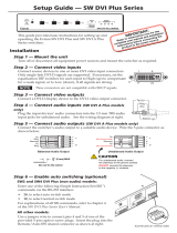
Power and Input Connections Output Connections Control Connections and
the Reset Button
A
AC power connector
B
Two configurable analog 15-pin HD (VGA)
connectors (inputs 1 and 2)
C
Three HDMI input connectors (inputs 3
through 5)
D
One RJ‑45 connector for DTP source
input
E
One 3.5 mm 5‑pole captive screw
connector for RS-232/IR Over DTP input
F
Five 3.5 mm, 5‑pole captive screw
connectors for analog audio input
(associated with inputs 1 through 5)
G
One 3.5 mm, 5‑pole (only 3 poles used)
mic/line audio input
H
Two 2‑position DIP switches for HDMI
mute and phantom power for mic/line
input
G
I
One 15‑pin HD connector for RGB video
output
J
One 3.5 mm 5‑pole captive screw
connector for RS-232/IR Over DTP
output
K
One RJ‑45 connector for DTP output
L
One 2‑position DIP switch for DTP or
HDMI output selection
M
One HDMI connector for HDMI video
output to a display
N
Mic mix level control
O
One 3.5 mm, 5‑pole fixed line level
output connector
P
One 3.5 mm, 5‑pole variable line level
output connector
Q
Amplified program audio output
connectors
R
One 3.5 mm, 3‑pole
captive screw RS‑232
connector for host
computer connection
S
Reset button
Figure 1. MPS602Rear Panel (MPS 602 SA shown)
A
AC power — IEC connector. Standard AC power: 100‑240 VAC, at 50‑60 Hz.
Video Input
B
RGB/VGA video input group — Two female 15‑pin HD connectors for VGA input (numbered 1 and 2 on the rear panel). The
connectors accept VGA signals.
NOTE: The MPS602 does not scale or convert video; however, it does convert an analog RGB/VGA input to digital
for digital output. The output signal resolution is the same as the input resolution.
C
HDMI video input group — Three HDMI connectors for HDMI compliant audio and video input (numbered 3, 4, and 5 on the
rear panel). Connect to any HDMI source device using standard HDMI cable.

2
MPS602 • Setup Guide (Continued)
Video Output
I
RGB video output — One 15‑pin HD connector acting as a pass‑through to output the selected RGB/VGA input (see
figure1 on page1).
M
HDMI video output — Connect an HDMI display device for output from the selected HDMI input (see figure1).
DTP
NOTE: The MPS602 can communicate with both DTP230 and DTP330 transmitters and receivers. The DTP330
connection has a maximum range of 330 feet (100 m). When connected to a DTP230 device, the connection is limited to
a maximum of 230 feet (70 m).
D
DTP In — Connect a DTP source (Tx) to this RJ‑45 connector, input 6 on the rear panel, (see figure1). The DTP signal format
and protocol is used. The DTP input includes the HDMI (or DVI with an appropriate adapter) video with embedded audio,
bidirectional RS‑232 and IR, separate balanced or unbalanced analog audio, and remote power for a connected DTP Tx
(transmitter) device (see Twisted Pair Recommendations for DTP Communication on page5).
E
RS-232 and IR (Over DTP) In — One 3.5mm 5‑pole captive screw connector to connect and pass bidirectional RS‑232 and
remote IR signals between the MPS602 and a DTP230 or DTP330 Tx device (see figure1).
J
RS-232 and IR (Over DTP) Out — One 3.5mm 5‑pole captive screw connector to connect and pass bidirectional RS‑232
and remote IR signals between the MPS602 and DTP230 or DTP330 Rx device (see figure1).
RS-232 and IR Over DTP Wiring
To pass bidirectional serial command and IR signals between connected DTP‑compatible devices, connect a control device
to the three leftmost poles (Tx, Rx, and G) of the 5‑pole captive screw connector.
NOTE: RS‑232 and IR data can be transmitted or received simultaneously.
K
DTP output — Connect a DTP receiver (Rx) to this RJ‑45 connector (see figure1). The DTP signal format and protocol
is used. The DTP output can include HDMI (with embedded audio), bidirectional RS‑232 and IR, separate balanced or
unbalanced analog audio (from the xed audio output), and remote power for a connected DTPRx (receiver) device.
L
DTP out or HDMI out selection switch — One single‑pole double‑throw switch to select either the DTP (
K
) or the
HDMI (
M
) output (see figure1).
Analog Audio Input
F
Audio input group —Five 3.5mm, 5‑pole captive screw connectors provide analog audio input to the switcher (see
figure1). Inputs 1‑5 accept either balanced or unbalanced audio. Adjust the audio level of each analog audio input using the
conguration software or using the front panel Audio Input Level Adjustment on page5.
Unbalanced Stereo Input
Balanced Stereo Input
Tip
Ring
Tip
Ring
Slee
ves
Do not tin the wires!
Tip
Sleeve
Sleeve
Tip
Unbalanced Mono Input
Balanced Mono Input
(high impedance)
Tip
Ring
Sleeve
LR
LR
LR
Tip
Sleeve
LR
Unbalanced Mic/Line Inpu
t
Tip
Sleeve
Ring
Balanced Mic/Line Input
Tip
Sleeve
Figure 2. Audio Input Connector Wiring
G
MicLine input — One 3.5mm, 3‑pole captive screw connector connects a mic or mono
line level audio device to the MPS602 (see gure at right). Use the conguration software to
select the mic or line input level.
H
Phantom Power and Mute HDMI — Two 2‑position DIP switches (see gure at right).
MUTE HDMI AUDIO (on left) mutes the HDMI embedded audio on both the HDMI output (
M
)
and the DTP output (
K
) (see figure1) when the switch position is UP .
PHANTOM POWER (on right) selects +48V phantom power for themic input (see gure at
right,
G
) when the switch position is UP.
NOTE: Although the rear mic/line input is 5‑pole, only 3 poles are used by the mic/line connector.
Be certain to plug the 3‑pole mic/line connector into the correct position (see figure at right).
MUTE HDMI AUDIO
PHANTOM POWER
AUDIO IN
L 3 R
MIC LINE
L
3
R
GH

3
Unbalanced Audio Output
Tip
No Ground Here
No Ground Here
Tip
Sleeves
LR
Balanced Audio Output
Tip
Ring
Tip
Ring
Sleeves
LR
Do not tin the wires!
Receive (Rx)
Transmit (Tx)
Bidirectional
RS-232
Device
Receive (Rx)
Transmit (Tx)
RxTx
Do not tin
the wires!
Ground ( )
Ground (
)
Program Audio Output
P
Variable audio output — 3.5mm, 5‑pole captive screw connector outputs the program audio (see figure1 on page1).
The level is controlled by the front panel volume encoder.
Control
R
RS-232 remote — 3.5mm, 3‑pole captive screw connector for connection of a host
computer, or a controller using Simple Instruction Set (SIS™). Wire the connector as
shown at right.
S
Reset button — With the MPS602 on, press and release this recessed button (see gure at right,
S
) to return
the MPS602 to the factory default settings.
L
R
SIG LINK
DTP IN
SIG LINK
DTP OUT
50/60 Hz
100-240V 1.0A MAX
1
2
RGB OUT
HDMI
MIC
MIX
RS-232
MPS 602 SA
Tx Rx G
MUTE HDMI AUDIO
PHANTOM POWER
SELECT
3
4
5
6
OUTPUTS
AMP OUT REMOTE
OVER DTP
OVER DTP
RS-232 IR
Rx GTx Tx Rx
RS-232 IR
Rx GTx Tx Rx
CLASS 2 WIRING
8Ω / 4Ω
INPUTS
AUDIO IN
AUDIO OUT
L 1 R L 2 R L 3 R
L
VARIABLE R
L FIXED R
L 4 R L 5 R
MIC LINE
R
L
R
SIG LINK
DTP IN
SIG LINK
DTP OUT
50/60 Hz
100-240V 1.0A MAX
1
2
RGB OUT
HDMI
MIC
MIX
RS-232
MPS 602 SA
Tx Rx G
MUTE HDMI AUDIO
PHANTOM POWER
SELECT
3
4
5
6
OUTPUTS
AMP OUT REMOTE
OVER DTP
OVER DTP
RS-232 IR
Rx GTx Tx Rx
RS-232 IR
Rx GTx Tx Rx
CLASS 2 WIRING
8Ω / 4Ω
INPUTS
AUDIO IN
AUDIO OUT
L 1 R L 2 R L 3 R
L VARIABLE R
L FIXED R
L 4 R L 5 R MIC LINE
R
Balanced and unbalanced program audio output is available on the MPS602 using a 3.5mm,
5‑pole captive screw connector. Refer to the illustration for proper wiring.
ATTENTION:
• For unbalanced audio, connect the sleeves to the ground contact. DO NOT connect the
sleeves to the negative (–) contacts.
• Pour l’audio asymétrique, connectez les manchons au contact au sol. Ne PAS connecter
les manchons aux contacts négatifs (–).
NOTE: Do not tin the audio leads. Tinned wires are not as secure in the connector and
could be pulled out. See below for wire stripping instructions.
N
Mic Mix — One potentiometer controls the Mic/Line input level (
G
) mixed into the xed program
audio output(
O
) (see gure at right).
O
Fixed audio output — The bottom 3.5mm, 5‑pole captive screw connector is for balanced or
unbalanced xed level program audio output (see
O
). The front panel knob does not control the
audio level from this audio output port.
Q
Amplified program audio output (SA and MA models only)
MA models — One green 5mm, 2‑pole locking captive screw connector for mono 70V output.
SA models — One green 5mm, 4‑pole locking captive screw connector for amplied dual channel output to a 4 or 8 ohm
speaker system (see gure at right).
AMP OUT
CLASS 2 WIRING
70V
L
R
AMP OUT
CLASS 2 WIRIN
G
8Ω / 4Ω
21
MPS 602 MA
MPS 602 SA
21
1
Strip and insert the speaker wires into the
connector and tighten the captive screws.
Be sure to observe the correct polarit
y.
2
Insert the wired connector into the amplifier
output and secure the locking screws on
either side.
Do not tin the wires!
Figure 3. Amplified Output Connector Wiring (SA and MA Models Only)

4
MPS602 • Setup Guide (Continued)
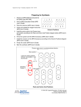
Step 3 — Setup and Operation
1 2 1 2 3 4 5 6
MPS SERIES
MEDIA PRESENTATION SWITCHER
MUTEMUTE
MICPROGRAM AUDIO
INPUTS
RGB
CONFIG
EXEC
MODE
AB DCE GHIJKLF
Figure 4. MPS602SA Front Panel
The MPS602 can be connected to as many as six input devices including a DTP transmitter. Either RGB input can be routed to
the RGB output. Separately, any of the six inputs (two RGB, threeHDMI, and one DTP) can be routed to either the DTP output or
the HDMI output, but not both.
NOTE: The RGB inputs can be switched to output on both the RBG output and HDMI/DTP output.
A
Power LED — The LED lights when power is applied to the MPS602.
B
Exec Mode LED — This red LED indicates the status of Executive (Exec) mode. Two levels of Exec mode, enabled and
disabled from the front panel, prevent accidental conguration changes from the front panel. Control and monitoring are still
accessible using RS‑232 or the front panel USB.
Exec mode 1 locks out all front panel controls. Exec mode 2 locks out the Mic Volume Encoder and Mute button.
To toggle exec mode:
1. Press and hold RGB Input 1 (
D
) for more than 3 seconds to enter the Exec Mode. All front panel LEDs blink once.
2. Continue to hold the RBG Input 1. Press and release Input 1 of the Inputs group (
E
) to toggle through the executive
modes in the following order:
a. If exec mode is not active (Exec Mode LED is off), the switcher toggles to executive mode 1. All front panel LEDs
(with the exception of the power and Exec Mode LEDs) blink three times. Release both buttons to enter exec
mode1. When enabled, if adjustments are attempted from the front panel, all input and mute LEDs blink once.
b. If the switcher is in exec mode 1, exec mode 2 is enabled and all front panel LEDs blink three times. Release both
buttons to enter exec mode 2. In this mode, the Mic Volume and Mute button are locked out. If adjustment of either
button is attempted from the front panel, the Mic Mute LED blinks once.
c. If currently in executive mode 2, the switcher exits executive mode and the Exec Mode LED turns off.
C
Config port — One USB mini‑B Cong port for host computer connection for conguration and upgrading rmware.
Video Control
D
RGB input group — Two green LEDs and associated buttons select and indicate the RGB input currently routed to the RGB
output.
The HDMI/DTP input group has six buttons with associated green LEDs. Press an input button in this group to switch it to the
selected (HDMI or DTP) digital output. The associated LED lights. Only one of the six inputs can be selected at a time.
E
RGB Inputs 1 and 2 — Select and indicate the current RGB input routed to the digital output (DTP or HDMI).
Analog RGB signals are converted to digital signals before routing to the DTP or HDMI output. RGB inputs are not scaled.
They are converted to digital signals at the same resolution.
F
HDMI Inputs 3 to 5 — Select and indicate the current HDMI input switched to the digital output (DTP or HDMI).
G
DTP Input 6 — Select and indicate the current DTP input switched to the digital output (DTP or HDMI).
Audio Control
The audio buttons and indicators provide control of the mic input and program audio output levels.
H
Mic Mute button and LED — Mute and unmute the Mic input. This mutes the Mic input for both the program audio output
and amplied audio output. When lit, the red LED indicates the Mic input is muted.
I
Mic Volume — Rotary encoder controls the Mic level mixed into the program audio output and amplied audio output (SA
and MA models). Rotate the knob clockwise to increase, and counterclockwise to decrease mic volume. If the mic volume is
muted, rotating the control unmutes the volume.
J
Program Audio Mute button and LED — Mutes and unmutes program and amplied audio. The red LED lights to indicate
program audio and amplied audio is muted.

5
S
F
S
F
S
F
S
F
S
F
S
F
S
F
S
F
S
F
S
F
S
F
S
F
S
F
S
F
Front Panel LEDs
VGA Input
1
VGA Input
2
Input 1
Input 2
Input 3
Input 4
Input 5
Input 6
Exec Mode
8765432
19
= on = off
= blinking fast = blinking slow
S
F
-10
-11
-12
-13
-14
-15
-16
-17
-18
+9
+8
+7
+6
+5
+4
+3
+2
+1
0
-1
-2
-3
-4
-5
-6
-7
-8
-9
+18
+17
+16
+15
+14
+13
+12
+11
+10
+24
+23
+22
+21
+20
+19
8
7
dB
6
5
432
19
K
Program Audio LEDs – Stacked LEDs indicate the program audio volume in dB. No
segments lit indicate a volume level of 0 dB. All segments lit represent full volume (+24 dB).
Segments in between track volume levels. The LEDs continue to display the current volume
level even when audio is muted (the red Mute LED lights).
L
Program Audio Volume – Rotary encoder controls the line level program audio output and
the amplied audio output (MPS602 SA and MPS602 MA only). It has no effect on the xed
audio output. Rotate the knob clockwise to increase and counterclockwise to decrease the
audio volume.
Audio Input Level Adjustment
Each analog audio input can be adjusted within a range of ‑18 dB to +24 dB. When adjusting the
audio level, the front panel LEDs used for RGB inputs 1 and 2 and Inputs 1 through 6 function as
indicators of the current audio level for the selected input as shown on the right.
Gain or attenuation is shown by the red Exec Mode LED: off indicates gain (+dB), on indicates
attenuation (‑dB).
To adjust an audio input level from the front panel:
1. Press and hold the Program Audio Mute and Mic Mute buttons until the two mute LEDs
blink 3 times (approximately 3 seconds).
2. Press the desired input button.
3. Once the input button is selected, the front panel input LEDs indicate the current gain or
attenuation setting. By default, all inputs are set to 0dB (all LEDs unlit). Rotate the Program
Audio Volume knob clockwise to increase and counterclockwise to decrease the selected
input audio level. The front panel LEDs track the level as the knob is turned.
4. Once the desired input level is set, the user can press the two mute buttons to exit, or within
3 seconds, select another input to adjust.
While in the input level adjustment mode, if a front panel button is not pressed or the Program
Audio Volume knob is not rotated for more than 3 seconds, the switcher times out and exits the
mode.
Twisted Pair Recommendations for DTP Communication
Extron recommends using the following practices to achieve full transmission distances up to
330 feet (100 m) and reduce transmission errors.
• Use Extron XTP DTP 24 STP cable for the best
performance. When not using XTP DTP 24 cable,
Extron recommends 24 AWG, solid conductor, STP
cable with a minimum bandwidth of 400 MHz.
• Terminate cables with shielded connectors to the
TIA/EIA T568B standard (shown to the right).
• Limit the use of more than two pass‑through points,
which may include patch points, punch down
connectors, couplers, and power injectors. If these
pass‑through points are required, use CAT 6 or 6a
shielded couplers and punch down connectors.
ATTENTION:
• Do not connect these devices to a computer data or telecommunications network.
• Ne connectez pas ces cartes appareils à des données informatiques ou à un réseau de
télécommunications.
• DTP is intended for indoors use only. No part of the network that uses DTP remote
power can be routed outdoors.
• DTP est destiné à une utilisation en intérieur uniquement. Aucune partie du réseau qui
utilise l’alimentation DTP à distance ne peut être routée en extérieur.
NOTE: When using shielded twisted pair cable in bundles or conduits:
• Do not exceed 40% ll capacity in conduits.
• Do not comb the cable for the rst 20 m, where cables are straightened, aligned, and secured in tight bundles.
• Loosely place cables and limit the use of tie wraps or hook and loop fasteners.
• Separate twisted pair cables from AC power cables.
12345678
Inser
t Twisted
Pair Wires
Pins:
Pin
1
2
3
4
5
6
7
8
Wire color
T568B
White-orange
Orange
White-green
Blue
White-blue
Green
White-brown
Brown

6
MPS602 • Setup Guide (Continued)
Extron Product Configuration Software (PCS)
PCS product conguration software combines multiple standalone product conguration modules in a single software application.
Product tabs along the top of the screen allow users to quickly choose between all open product congurations. The MPS602 is
congured via USB connection only.
To congure an MPS602 switcher using PCS, install the software (available on the Extron website, www.extron.com) to a PC
connected to the switcher via the front panel USB Cong port. After the installation, start the program and choose the connection
option. For full instructions on PCS operation, press <F1> or click the icon in the upper right corner (see gure 5,
7
) and select
Extron PCS Help.
Click on the installed desktop icon to start the program. The main window opens to the Device Discovery panel. The
application lists all the Extron AV devices connected on the local network or via USB.
Device Discovery Panel
PCS opens to the Device Discovery panel. This panel lists the accessible devices on the local network or connected via USB.
You can also start a new conguration le, or open an existing conguration le for ofine work. When PCS is operating, device
discovery searches for PCS supported Extron devices. The search includes the network the PC is connected to, and devices
connected to the PC via USB. All “discovered” TCP/IP and USB connected devices are listed. The list has four columns:
• The model name (see gure 5,
1
)
• IP Address (
2
) (blank for the MPS602 connected via USB)
• Device name (
3
) (this can be derived from the model name and last three octets of the MAC address, or the model name
and the part number of the device)
• Connection type (
4
).
NOTE: If the model name of the device has not changed, the default Model Name (
1
) is the model name plus the part
number of the device. The Device Name (
3
) is the model name of the device and the last three octets of the MAC address
if the connection is TCP/IP or the name of the device for USB.
11 22 33 44
7
7
5
5
Connect
66
Figure 5. PCS, Device Discovery Panel
Click on the heading at the top of any column to sort the device list (ascending or descending).
In the Device Discovery list, look for your device (the MPS602 only supports USB connection). The name listed in the Model
column (see gure 5,
1
) is the MPS602 model name (by default, the MPS602 model number plus the part number). The Device
Name column (
3
) can be the default name (MPS602 plus the model sufx), or the name given it from a previous PCS session
(see the MPS 602 Series User Guide or the device help le for information on how to change the device name).

7
To connect to any device in the Device Discovery list:
• <Double‑click> on the device name (see figure 5,
5
on page 6 ), or
• <Single click> on the name (the row is highlighted) and click Connect (
6
).
When the device connects, PCS opens to the conguration page for that device. Follow the specic product help le to congure
the device.
Connect to Additional Devices
If at any time you wish to connect to a different device using device discovery:
1. Click + on the tab at the top left of the toolbar (see gure 6,
1
).
11
Figure 6. New Device Configuration
The Device Discovery panel opens (see figure 5 on page6)
2. See “To connect to any device in the Device Discovery list” (above) to connect to a new device.
NOTE: Devices currently open in PCS are not listed.
3. The device opens in a new tab.

68-2358-50
Rev. B 11 15
Extron Headquarters
+800.633.9876 Inside USA/Canada Only
Extron USA - West Extron USA - East
+1.714.491.1500 +1.919.850.1000
+1.714.491.1517 FAX +1.919.850.1001 FAX
Extron Europe
+800.3987.6673
Inside Europe Only
+31.33.453.4040
+31.33.453.4050 FAX
Extron Asia
+65.6383.4400
+65.6383.4664 FAX
Extron Japan
+81.3.3511.7655
+81.3.3511.7656 FAX
Extron China
+86.21.3760.1568
+86.21.3760.1566 FAX
Extron Middle East
+971.4.299.1800
+971.4.299.1880 FAX
Extron Korea
+82.2.3444.1571
+82.2.3444.1575 FAX
Extron India
1800.3070.3777
(Inside India Only)
+91.80.3055.3777
+91.80.3055.3737 FAX
© 2015 Extron Electronics All rights reserved. All trademarks mentioned are the property of their respective owners. www.extron.com
/