GUIDE TO INSTALLATION AND OPERATION
8 | UAP-1783
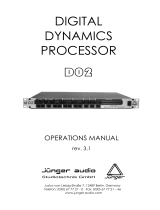
OFF, UPMIX, DOWNMIX
AUTO, MANUAL
CUT, -6, -4.5, -3, -1.5, 0, +1.5, +3.0, +4.5, +6 dB
OPERATION MODE
CUT, -6, -4.5, -3, -1.5, 0, +1.5, +3.0, +4.5, +6
LFE
SURROUND
LEVELS
DOWNMIX MODE
dB
UPMIX TYPE
0, 1, ..., 7, ..., 10
dB
CENTER LEVEL
CUSTOM SETTINGS
dB
OFF, 80 Hz, 120 Hz
OFF, UPMIX, DOWNMIXOPERATION MODE
OFF, UPMIX, DOWNMIXOPERATION MODE
or
or
UPMIX/DOWNMIX
UPMIX SOURCE CH1, CH2, …, CH16LEFT INPUT
RIGHT INPUT CH1, CH2, …, CH16
LFE LEVEL
dB
DOWNMIX SOURCE CH1, ..., CH9, ..., CH16
OUTPUT MIXERS ANALOG 1L
ANALOG 1R
ANALOG 2L
ANALOG 2R
SOURCE A
OFF, A, SUM A+B, 2 INPUT MIX [, 4 INPUT MIX (even CH) ]
1, 2, ..., 16
A1, V, A2A-BUS SELECT
CHANNEL SELECTSOURCE B (SUM,MIX)
MODE
LEVEL (A,MIX)
LEVEL (SUM)
MUTE OFF, ON
CUT, -95.5, ..., -0.5, 0, +0.5, ..., +12.0 dB
OFF, ON XXXX
DESTINATION
SOURCECH STATUS ID (AES)
-6.0, -3.0, 0.0
AES 2L
AES 2R
AES 1L
AES 1R
dB
0 dBFS SETTING INPUT (A/D) parameter dBu = 0 dBFS
OUTPUT (D/A)
parameter = 0, 1, ..., 24
0 dBFS = parameter dBu
dB
LtRt, LoRoTYPE
SPEECH, MUSIC, MOVIE, CUSTOM
CONTROL
dB
LEFT/RIGHT LEVEL
LFE FILTER
CUT, -24, -23, ..., 0, ..., +5, +6
SRND LEVEL
EFFECT INTENSITY
CUT, -6, -4.5, -3, -1.5, 0, +1.5, +3.0, +4.5, +6
CUT, -6, -4.5, -3, -1.5, 0, +1.5, +3.0, +4.5, +6
OUTPUT
LEFT/RIGHT
NORMALIZED, DIRECT
CENTER
LEFT INPUT
CH1, ..., CH10, ..., CH16
CH1, ..., CH11, ..., CH16
CH1, ..., CH12, ..., CH16
CH1, ..., CH13, ..., CH16
CH1, ..., CH14, ..., CH16
RIGHT INPUT
CENTER INPUT
LFE INPUT
SRND LEFT INPUT
SRND RIGHT INPUT
available if custom
type is selected
SRND TYPE
SRND DELAY
SRND 90' FILTER
LEFT/RIGHT WIDTH
SPEECH, MUSIC, MOVIE
0, 1, ..., 20 ms
OFF, ON
0, 1, ..., 32
CUT, -24, -23, ..., 0, ..., +5, +6
CUT, -24, -23, ..., 0, ..., +5, +6
CUT, -24, -23, ..., 0, ..., +5, +6
1, 2, ..., 15, ..., 255 s
-72, -66, -60, -54, -48 dBFS
MONITORING
NSD
NSD DELAY
NSD THRESHOLDCH1
...
CH16
ANALOG OUT 1L, ANALOG OUT 1R, ANALOG OUT 2L, ANALOG
OUT 2R, AES OUT 1L, AES OUT 1R, AES OUT 2L, AES OUT 2R
(list depends on rear)
LEFT
RIGHT
ANALOG OUT 1L, ANALOG OUT 1R, ANALOG OUT 2L, ANALOG
OUT 2R, AES OUT 1L, AES OUT 1R, AES OUT 2L, AES OUT 2R
(list depends on rear)