
Freescale Semiconductor Document Number: MMA865xFCSTUG
User’s Guide Rev. 0, 10/2012
© 2012 Freescale Semiconductor, Inc. All rights reserved.
Contents
MMA865xFC Sensor Toolbox
User’s Guide
1 Introduction
The Freescale MMA865xFC sensor toolbox
accelerometer kit provides hardware and software for the
demonstration and evaluation of the Xtrinsic
MMA865xFC accelerometers (MMA8652FC,
MMA8653FC). This user’s guide shows you how to use
this kit.
The MMA865xFC kit includes the following:
• MMA865x interface board
• MMA8652FC accelerometer daughter board
• MMA8653FC accelerometer daughter board
The kit requires a USB-interface board to attach the kit
to a personal computer. Both items can be purchased on
the Freescale website.
• MMA865xFC kit, part number LFSTBEB865x
• MMA865x USB-interface board, part number
LFSTBUSB
• Optional 9V battery board (for non-volatile
memory datalogging), part number LFSTBBAT9
1 Introduction . . . . . . . . . . . . . . . . . . . . . . . . . . . . . . . . . . . 1
2 About the MMA865x Accelerometers . . . . . . . . . . . . . . . 2
3 Getting Started . . . . . . . . . . . . . . . . . . . . . . . . . . . . . . . . 3
3.1 Connecting the kit . . . . . . . . . . . . . . . . . . . . . . . . . . 3
3.2 Installing the sensor toolbox software . . . . . . . . . . . 4
4 Understanding the Accelerometer Demonstrations . . . . . 8
4.1 Opening the sensor toolbox software . . . . . . . . . . . 8
4.2 Directional Flick application . . . . . . . . . . . . . . . . . . 10
4.3 Tilt Detection application . . . . . . . . . . . . . . . . . . . . 14
4.4 Orientation application. . . . . . . . . . . . . . . . . . . . . . 17
4.5 Graphical Datalogger application . . . . . . . . . . . . . 21
4.6 NVM Datalogger application . . . . . . . . . . . . . . . . . 26
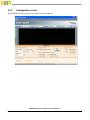
4.7 Configuration screen . . . . . . . . . . . . . . . . . . . . . . . 29
4.8 Directional Tap with FIFO application . . . . . . . . . . 31
4.9 Directional Shake with FIFO application . . . . . . . . 36
4.10 Full-System Evaluation application . . . . . . . . . . . . 41
5 Running the Accelerometer Demonstrations. . . . . . . . . 62
5.1 Directional Flick application . . . . . . . . . . . . . . . . . . 62
5.2 Orientation (Portrait/Landscape) application . . . . . 62
5.3 Graphical Datalogger application . . . . . . . . . . . . . 62
5.4 Non-Volatile Memory Datalogger application . . . . 63
5.5 Directional Tap with FIFO application . . . . . . . . . . 63
5.6 Directional Shake with FIFO application . . . . . . . . 63
6 Revision History. . . . . . . . . . . . . . . . . . . . . . . . . . . . . . . 64

MMA865xFC Sensor Toolbox User’s Guide, Rev. 0
2 Freescale Semiconductor, Inc.
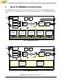
2 About the MMA865x Accelerometers
The MMA8652FC device provides 12 bits of resolution and more features. The MMA8653FC device
provides 10 bits of resolution with fewer features. For more information, also see the MMA865xFC data
sheet.
Figure 1. MMA8652 block diagram
Figure 2. MMA8653 block diagram
C-to-V
Converter
SDA
SCL
I
2
C
Embedded
Functions
C-to-V
Internal
OSC
Clock
GEN
ADC
Converter
VDDIO
GND
X-axis
Transducer
Y-axis
Transducer
Z-axis
Transducer
32 Data Point
Configurable
FIFO Buffer
with Watermark
Freefall
and Motion
Detection
Transient
Detection
(i.e., fast motion,
jolt)
Enhanced
Orientation with
Hysteresis
and Z-lockout
Single, Double
Auto-WAKE/Auto-SLEEP Configurable with debounce counter and multiple motion interrupts for control
VDD
& Directional Tap
Detection
INT1
INT2
BYP
Interface
MUX
Voltage
Regulator
Gain AAF
Anti-Aliasing
Filter
C-to-V
Converter
SDA
SCL
I
2
C
Embedded
Functions
C-to-V
Internal
OSC
Clock
GEN
ADC
Converter
VDDIO
GND
X-axis
Transducer
Y-axis
Transducer
Z-axis
Transducer
Freefall
Detection
Orientation with
Hysteresis
and Z-lockout
Auto-WAKE/Auto-SLEEP Configurable with debounce counter and multiple motion interrupts for control
VDD
INT1
INT2
BYP
Interface
MUX
Voltage
Regulator
Gain AAF
Anti-Aliasing
Filter

MMA865xFC Sensor Toolbox User’s Guide, Rev. 0
Freescale Semiconductor, Inc. 3
3 Getting Started
To begin using the kit, connect it to your PC (Section 3.1, “Connecting the kit”) and install the sensor
toolbox software (Section 3.2, “Installing the sensor toolbox software”).
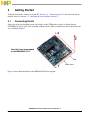
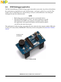
3.1 Connecting the kit
Select one of the two daughter boards and attach it to the USB interface board, as directed in the
LFSTBEB8491 Quick Start Guide included with the boards. When assembled, the device detection axes
are as shown in Figure 3.
Figure 3. Board assemblies
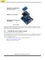
Figure 4 shows how the boards of the MMA865xFC kit fit together.
How the 3 axes are mapped
to the MMA865xFC kit
X
Z
Y
USB
Power switch

MMA865xFC Sensor Toolbox User’s Guide, Rev. 0
4 Freescale Semiconductor, Inc.
Figure 4. How the three boards are connected together
Connect the LFSTBUSB USB-interface board to a spare USB port on a Windows-based PC, using the
USB cable that comes with the USB board. If the board’s red power LED does not illuminate, check the
board’s power switch, near its USB connector.
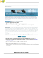
3.2 Installing the sensor toolbox software
Perform the following procedure to install the software.
Near the end of this process, you will be asked if you want to install a serial-to-USB driver included with
the sensor toolbox. If you have been previously used Freescale's sensor toolbox software, these drivers
already are installed on your PC.
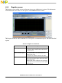
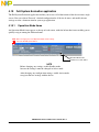
1. To download the sensor toolbox software, click the following link:
http://www.freescale.com/sensortoolbox.
The webpage, shown next, appears.
MMA8652FC (or MMA8653FC)
MMA865x USB-interface board
MMA845x interface board
accelerometer board
(LFSTBUSB)

MMA865xFC Sensor Toolbox User’s Guide, Rev. 0
Freescale Semiconductor, Inc. 5
2. Click the Download Software button.
The Sensor Toolbox Installer license agreement page appears.
3. Scroll down to the bottom of the page, shown below, and click the I Accept button.
4. Save the software’s installation executable file (SensorToolboxInstaller.exe) to your PC.
5. If you have not already connected the toolkit to your PC, perform the procedure in Section 3.1,
“Connecting the kit”.
6. Locate the installation file on your PC and double-click on it.
7. Proceed through the setup wizard’s series of dialog boxes.
During the process, you will be asked if you want a Sensor Toolbox icon added to your Start menu
and desktop.

MMA865xFC Sensor Toolbox User’s Guide, Rev. 0
6 Freescale Semiconductor, Inc.
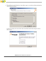
8. When the Ready to Install dialog box, shown below, appears, review the installation configuration
and click the Install button.
A progress bar displays the status of the software installation and the final dialog box, shown
below, appears.

MMA865xFC Sensor Toolbox User’s Guide, Rev. 0
Freescale Semiconductor, Inc. 7
9. Do any of the following and click the Finish button:
— To install the Future Technology Devices International (FTDI) serial-to-USB communications
driver, enable the Install FTDI Driver checkbox.
— To launch the toolbox software upon completion of the setup, leave the Run Sensor Toolbox
checkbox enabled.
If you chose to install the FTDI driver, a command-line window briefly appears.
The application is now ready for use.

MMA865xFC Sensor Toolbox User’s Guide, Rev. 0
8 Freescale Semiconductor, Inc.
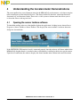
4 Understanding the Accelerometer Demonstrations
The sensor toolbox has several demonstrations for the MMA865xQ accelerometers, each showcasing the
built-in intelligence of the individual devices. The demos include tilt detection, orientation detection,
directional tap, and directional shake. There also is a full-system evaluation mode that allows you to
evaluate the sensor at the register level.
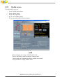
4.1 Opening the sensor toolbox software
To launch the toolbox software, either double-click on the application’s desktop icon or choose Start >
Programs > Sensor Toolbox > Sensor Toolbox. This displays the sensor toolbox’s hardware-detection
dialog box, shown below.
If the LFSTBUSB USB-interface board is connected properly, then the software will detect which of the
MMA865xQ daughter boards is attached to the evaluation board, and display the device-specific menus.
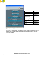
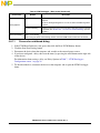
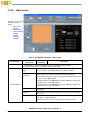
Upon device connection, the software displays the demo launcher menu, shown in the next illustration.

MMA865xFC Sensor Toolbox User’s Guide, Rev. 0
Freescale Semiconductor, Inc. 9
• To launch a demo, click on its box.
• To navigate to a different demo, close the browser window for the current demo and click on a
different demo box in the launcher menu, which remains in the background as long as the
application is running.
Full System Evaluation page 41
Directional Flick page 10
Hi Resolution Tilt Detection page 14
(MMA8652 only)
Low Resolution
Portrait/Landscape
page 17
Graphical Datalogger page 21
NVM Datalogger page 26
Directional Shake Low-Power
with FIFO
page 36
(MMA8652 only)
Directional Tap Low-Power
with FIFO
page 31
(MMA8652 only)

MMA865xFC Sensor Toolbox User’s Guide, Rev. 0
10 Freescale Semiconductor, Inc.
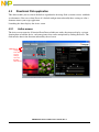
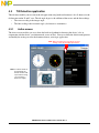
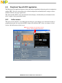
4.2 Directional Flick application
This demo enables you to evaluate the built-in algorithm for detecting flicks (transient events) with both
accelerometers. You can evaluate Freescale’s default configuration and modify those settings to tailor a
demonstration to your target application.
Launching the demo displays the Active screen.
4.2.1 Active screen
The Active screen contains a Direction Event Detected indicator with a direction text display, a picture
showing how to hold the device, and some pictures that can be manipulated by flicking the device. The
flick must be done in the direction indicated by the red arrow.
Note: Before
changing any
of the Active
screen’s
settings,
select the
Standby
option button.

MMA865xFC Sensor Toolbox User’s Guide, Rev. 0
Freescale Semiconductor, Inc. 11
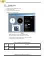
4.2.2 Standby screen
Use the Standby screen to:
• Change the sample rate of the device
• Set the dynamic range
• Change the over-sampling setting
• Calibrate the device
• Change the device state and the parameters for detecting transient events
NOTE
Before changing any settings, enable Standby mode,
because the settings cannot be changed in Active mode.
After changing any configuration settings, enable Active mode,
to register the new settings with the device.
The screen contains the following
menu frames:
• Standby Active
• Operation Mode
• Dynamic Range
• Transient Settings
Note: To modify the
default
configuration,
first enable
the Standby
option button
on the left
side of the
screen.

MMA865xFC Sensor Toolbox User’s Guide, Rev. 0
12 Freescale Semiconductor, Inc.
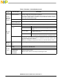
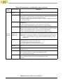
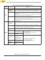
Table 1. Directional Flick – Active/Standby screens
Screen
frame
Field or option Description
Operation
Mode
Sample Rate Enables you to change the rate at which the device acquires data.
Over-Sampling
Options for Data
Normal Mode Normal operation.
Hi Res Mode The device gives more accurate readings, but draws more current.
Low Power Mode The device draws less current than Normal mode, but at the
expense of accuracy.
Low Noise Low Power The device draws more current Normal mode, but less than Low
Power mode and reduces noise.
Auto Calibrate Directs the device to calculate the offsets for each axis (account for any error in
measurements). For maximum resolution, the calibration is done with a dynamic range of 8g
and a sample rate of 1.563 Hz.
Note: Before enabling this mode, place the device on a flat and stationary surface.
Dynamic
Range
•2g
•4g
•8g
Sets the range over which the accelerometer is acquiring data.
Standby
Active
Standby Sets the device to Standby mode.
Active Sets the device to Active mode.
•Standby Mode
• Wake Mode
• Sleep Mode
Indicates the device’s status (Read only).
Note: The device will never enter Sleep mode during this demo.
Transient
Settings
Default Transient
Settings
Sets the parameters for detecting flicks to their working values, as defined at the factory.
Bypass HPF
(High-Pass Filter)
Directs the application to use the raw accelerometer data before it has been passed through
the HPF.
Note: The Bypass HPF setting should normally be disabled.
• Enable X Flag
• Enable Y Flag
• Enable Z Flag
Allows flicks along these axes to trigger the “Event Detected” Indicator on the Demo Screen.
Note: Only the Y axis will move the pictures and correctly trigger the direction indicator.
If enabled, the X and Z axes will only trigger the Event Detected indicator on the Demo
screen.
Enable Latch Causes any triggered event to remain until the Status register is read. If this checkbox is not
enabled, the interrupt will only last as long as the event and the Status register will represent
the most-recent event.
This setting should be enabled for the flick detection to work properly. If it is disabled, the
events that are moving the pictures will constantly occur as you move the device and the
pictures will simply flick from end to end.

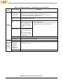
MMA865xFC Sensor Toolbox User’s Guide, Rev. 0
Freescale Semiconductor, Inc. 13
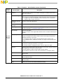
Transient
Settings
(
continued
)
Threshold Sets the threshold for flick events to be detected. Flicks at a smaller g-force than this value
are filtered out.
To move the slider, the Reset button must be clicked.
After the selection is made, click the Set button to change the setting.
Debounce This slider sets the amount of time that the configured conditions must be in place to trigger
the main flick event. Any event whose duration does not exceed this time will not trigger an
interrupt.
To move the slider, the Reset button must be clicked.
After the selection is made, click the Set button to change the setting.
Decrement
Debounce
Selecting this option causes the Debounce timer to be decremented each time an event fails
to reach the debounce time.
Clear Debounce Selecting this option causes the timer set by the Debounce slider to reset each time an event
fails to reach the debounce time.
Set Saves the new configuration settings after the repositioning of the Threshold and Debounce
sliders.
Reset Enables the moving of the Threshold and Debounce sliders.
Table 1. Directional Flick – Active/Standby screens (Continued)
Screen
frame
Field or option Description

MMA865xFC Sensor Toolbox User’s Guide, Rev. 0
14 Freescale Semiconductor, Inc.
4.3 Tilt Detection application
This tilt demo enables you to evaluate the tilt application using both accelerometers' data. It showcases the
tilt detection on the X and Y axes. The tilt angle degree is the addition of the coarse and the fine readings:
• The coarse reading is the integer angle.
• The fine reading is the fractional angle (also known as arcminutes).
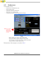
4.3.1 Active screen
The Active screen enables you to evaluate the built-in algorithm for detecting the device’s tilt, in
conjunction with the device’s resolution mode (coarse or fine). You can evaluate the default configuration
and modify the settings to tailor the demonstration to your target application.
Note: Before changing any of the Active screen’s
settings, select the Standby option button.
Note: In order for the tilt to
be registered, the
device must be held
up so that it is facing
you (or held on a
desk on its edge).

MMA865xFC Sensor Toolbox User’s Guide, Rev. 0
Freescale Semiconductor, Inc. 15
4.3.2 Standby screen
Use the Standby screen to:
• Change the device Standby/Active state
• Set the dynamic range
• Change the sample rate of the device
• Change the over-sampling setting
NOTE
Before changing any settings, enable Standby mode,
because the settings cannot be changed in Active mode.
After changing any configuration settings, enable Active mode,
to register the new settings with the device.
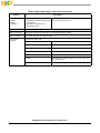
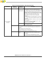
Table 2. Tilt Detection – Active/Standby screens
Screen
frame
Field or option Description
Tilt Angle
Degree
Coarse Indicates the angle the device is being held at, along the X and Y axes (degrees).
Fine Shows the Arcminutes value of the angle (where an arcminute is equal to1/60 of a
degree).

MMA865xFC Sensor Toolbox User’s Guide, Rev. 0
16 Freescale Semiconductor, Inc.
Operation
Mode
Sample Rate Enables you to change the rate at which the device acquires data.
Note: The tilt demo will not function at the 1.563 Hz Sample Rate.
Over-Sampling
Options for Data
Normal Mode Normal operation.
Hi Res Mode The device gives more accurate readings, but draws more
current.
Low Power Mode The device draws less current than Normal mode does, but at
the expense of accuracy.
Low Noise Low Power The device draws more current than Normal mode does, but less
current than Low Power mode does, and reduces noise.
Auto Calibrate Directs the device to calculate the offsets for each axis (accounting for any error in
measurements). For maximum resolution, the calibration is done with a dynamic range of
8g and a sample rate of 1.563 Hz.
Note: Before enabling Auto Calibrate mode, place the device on a flat and stationary
surface.
Note: Before returning to active mode, it is necessary to set the Sample Rate back to a
usable value, because running Auto Calibrate sets the device to the 1.563 Hz
Sample Rate (a frequency at which the tilt application cannot function).
Dynamic
Range
•2g
•4g
•8g
Sets the range over which the accelerometer is acquiring data.
Standby
Active
Standby Sets the device to Standby mode.
Active Sets the device to Active mode.
• Standby Mode
• Wake Mode
• Sleep Mode
Indicates the device’s status (Read only).
Note: The device will never enter Sleep mode during this demo.
Table 2. Tilt Detection – Active/Standby screens (Continued)
Screen
frame
Field or option Description

MMA865xFC Sensor Toolbox User’s Guide, Rev. 0
Freescale Semiconductor, Inc. 17
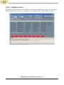
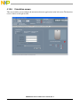
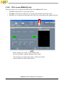
4.4 Orientation application
The Orientation application demo enables you to evaluate the built-in Portrait/Landscape algorithm for
detecting orientation. Using this application, you can evaluate Freescale’s default configuration, as well as
change the settings to tailor the demonstration to your target application
4.4.1 Active screen
The Active screen contains a Portrait/Landscape gauge and a Back/Front gauge. The Portrait/Landscape
gauge has 5 options: UP, DOWN, LEFT, RIGHT, and Lockout. The Back/Front gauge shows 2 options:
BACK/FRONT.
The image below the gauge is a simulated mobile phone that displays the same orientation indicated by
the gauges. The information is provided by the device's accelerometer data.
Note: Before changing any of the Active screen’s
settings, select the Standby option button.

MMA865xFC Sensor Toolbox User’s Guide, Rev. 0
18 Freescale Semiconductor, Inc.
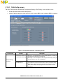
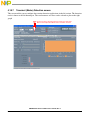
4.4.2 Standby screen
Use the Standby screen to:
• Set the device’s Standby/Active state
• Set the dynamic range
• Change the sample rate of the device
• Change the over-sampling setting
• Change the parameters for detecting orientation changes
NOTE
Before changing any settings, enable Standby mode,
because the settings cannot be changed in Active mode.
After changing any configuration settings, enable Active mode,
to register the new settings with the device.
Each menu frame’s fields and options are described in Table 3.
Note: Before changing
the Orientation
Detection values,
select the Enable
P/L button.

MMA865xFC Sensor Toolbox User’s Guide, Rev. 0
Freescale Semiconductor, Inc. 19
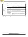
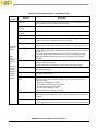
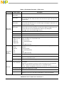
Table 3. Orientation – Active/Standby screens
Screen
frame
Field or option Description
Portrait /
Landscape
Detection
Display
Portrait/Landscape Shows the angle of the X and Y axes of the device.
If the device is tilted past the Z-lockout angle, then changes in the X and Y axes are
ignored and the gauge displays “Lock Out.” To resume orientation detection, rotate the
device away from the Z-lockout angle.
Back/Front Displays the Front/Back angle of the device.
Simulated Graphic
Display (mobile phone)
Orients the phone at the angle indicated by the data from the accelerometer.
Operation
Mode
Sample Rate Enables you to change the rate at which the device acquires data.
Over-Sampling Options
for Data
Normal Mode Normal operation.
Hi Res Mode The device gives more accurate readings, but draws more
current.
Low Power Mode The device draws less current than Normal mode does, but at
the expense of accuracy.
Low Noise Low Power The device draws more current than Normal mode does, but
less current than Low Power mode does, and reduces noise.
Auto Calibrate Directs the device to calculate the offsets for each axis (account for any error in
measurements). For maximum resolution, the calibration is done with a dynamic range
of 8g and a sample rate of 1.563 Hz.
Note: Before enabling this mode, place the device on a flat and stationary surface.
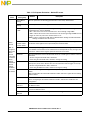
Dynamic
Range
•2g
•4g
•8g
Sets the range over which the accelerometer is acquiring data.
Standby
Active
Standby Sets the device to Standby mode.
Active Sets the device to Active mode.
•Standby Mode
• Wake Mode
• Sleep Mode
Indicates the device’s status.
Note: The device will never enter Sleep mode during this demo.

MMA865xFC Sensor Toolbox User’s Guide, Rev. 0
20 Freescale Semiconductor, Inc.
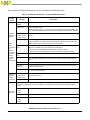
Orientation
Detection
settings
Enable P/L Enables the frame’s settings to be modified. Clearing the checkbox will prevent the
demo from functioning.
Set Default Settings Resets the frame’s settings to the default values defined at the factory.
Note: Selecting the “Set Default Settings” option will lock the values in the text boxes to
its right. If you want to change those values manually, then the “Set Default
Settings” option must be de-selected.
Portrait-To-Landscape
Tr i p A n gle
Shows the current value (Read only).
Landscape-To-Portrait
Tr i p A n gle
Shows the current value (Read only).
Z-Lock Angle Changes the Z-axis angle at which the device will ignore changes in orientation.
(For more information, see “Orientation application.”)
B/F Trip Angle (Back/Front Trip Angle)
Changes the range of z-axis angles within which the device considers itself facing front
and back.
P-L Trip Angle (Portrait-to-Landscape Trip Angle)
Changes the
midpoint
of the angle at which the device will change from portrait to
landscape orientation, or vice versa.
• For changing to right, the angle is measured down from the positive X axis.
• For changing to the left, landscape orientation, the angle is measured up from the
X-axis.
Hysteresis Angle Changes the
distance from the
midpoint
of the angle at which the device will change
from portrait to landscape orientation, or vice versa.
The actual trip angle for changing orientation is the P-L angle ± this angle.
Debounce Changes the time that the device waits after a physical orientation change is detected,
before triggering an orientation-change interrupt.
To move the Debounce slider, the Reset button must be clicked.
After the Debounce selection is made, click the Set button to change the setting.
Decrement Debounce Causes the Debounce timer to decrement each time that an event fails to reach the
debounce time.
Clear Debounce Causes the timer set by the Debounce slider to reset each time that an event fails to
reach the debounce time.
Set Saves the new configuration settings after the repositioning of the Threshold and
Debounce sliders.
Reset Enables you to move the Threshold and Debounce sliders.
Table 3. Orientation – Active/Standby screens (Continued)
Screen
frame
Field or option Description
Page is loading ...
Page is loading ...
Page is loading ...
Page is loading ...
Page is loading ...
Page is loading ...
Page is loading ...
Page is loading ...
Page is loading ...
Page is loading ...
Page is loading ...
Page is loading ...
Page is loading ...
Page is loading ...
Page is loading ...
Page is loading ...
Page is loading ...
Page is loading ...
Page is loading ...
Page is loading ...
Page is loading ...
Page is loading ...
Page is loading ...
Page is loading ...
Page is loading ...
Page is loading ...
Page is loading ...
Page is loading ...
Page is loading ...
Page is loading ...
Page is loading ...
Page is loading ...
Page is loading ...
Page is loading ...
Page is loading ...
Page is loading ...
Page is loading ...
Page is loading ...
Page is loading ...
Page is loading ...
Page is loading ...
Page is loading ...
Page is loading ...
Page is loading ...
Page is loading ...
-
 1
1
-
 2
2
-
 3
3
-
 4
4
-
 5
5
-
 6
6
-
 7
7
-
 8
8
-
 9
9
-
 10
10
-
 11
11
-
 12
12
-
 13
13
-
 14
14
-
 15
15
-
 16
16
-
 17
17
-
 18
18
-
 19
19
-
 20
20
-
 21
21
-
 22
22
-
 23
23
-
 24
24
-
 25
25
-
 26
26
-
 27
27
-
 28
28
-
 29
29
-
 30
30
-
 31
31
-
 32
32
-
 33
33
-
 34
34
-
 35
35
-
 36
36
-
 37
37
-
 38
38
-
 39
39
-
 40
40
-
 41
41
-
 42
42
-
 43
43
-
 44
44
-
 45
45
-
 46
46
-
 47
47
-
 48
48
-
 49
49
-
 50
50
-
 51
51
-
 52
52
-
 53
53
-
 54
54
-
 55
55
-
 56
56
-
 57
57
-
 58
58
-
 59
59
-
 60
60
-
 61
61
-
 62
62
-
 63
63
-
 64
64
-
 65
65


NXP MMA8652FC User guide
- Type
- User guide
Ask a question and I''ll find the answer in the document
Finding information in a document is now easier with AI
Related papers
-
NXP RDMMA865X Operating instructions
-
-
-
-
-
-
-
-
-
NXP MMA6261Q User guide
Other documents
-
CMA ML29s User guide
-
 freescale Elerometer Prototype User guide
-
TEAC CA-10 User manual
-
3M Detection Solutions DL DPR Operating instructions
-
Freescale Semiconductor i.MX 6UltraLite Hardware User's Manual
-
-
-
-
Freescale Semiconductor 6.0/Windows User manual
-
Renishaw XCal-View User guide
