NXP MMA6261Q User guide

Type
User guide

This manual is also suitable for

© Freescale Semiconductor, Inc., 2005. All rights reserved.
AN1986
Rev 1, 05/2005
Freescale Semiconductor
Application Note
Using the TRIAX Evaluation Board
by: Michelle Clifford
Sensor Products Division, Tempe, AZ
INTRODUCTION
Using micro machining and integrated circuit technology,
Freescale produces highly reliable, capacitive, acceleration
sensors. Freescale’s accelerometers were initially designed
for front- and side-impact airbags in the automotive arena, but
now there are extensive applications in medical, appliance,
consumer, and industrial areas such as high-end washing
machines, gaming devices, LCD projectors, robotics, and
fitness equipment.
TRIAX Board Overview
The TRIAX demo was built to combine many of the demos
that we have available for accelerometers. These modules
enable you to see how accelerometers can add additional
functionality to many applications in different industries. By
thinking of accelerometer applications in terms of the
measurements performed, they can be grouped into five
categories
Tilt, Position, Movement, Vibration, and
Shock. This document describes the different demos
available for each of the five categories of accelerometer
measurement and how they can be demonstrated using the
TRIAX board.
The TRIAX board is designed for three-axis sensing.
Freescale offers three-axis sensing in several different ways.
A three accelerometer solution can be achieved using two
X-axis accelerometers in a 16-pin SOIC package, with one
device rotated 90 degrees from the other to achieve X and Y
axis sensing, and a Z-axis accelerometer in a 16-pin SOIC
package. A two accelerometer solution is achieved using the
MMA6260D, which is an X and Y-axis device and a Z-axis
accelerometer, both in 6x6x2mm QFN packages. Sensor
Products is in development with three-axis sensing in a single
package.
Tilt
Tilt Applications refer to Inclinometers, Anti-Theft Devices,
Game pads for Video Games or Joysticks, Sports Diagnostics
and Physical Therapy Applications, PDAs, LCD Projection,
and Camcorder Stability.
Figure 1. TRIAX Board and Corresponding Axis
Medical Applications for tilt range from Physical Therapy
devices to Medical Equipment monitoring, where the
accelerometers are used to ensure that the equipment is
being used properly. For example, wrist mounted heartbeat
monitors obtain the most accurate measurement if the blood
pressure sensing device is at the same elevation as your
heart. By using an accelerometer to measure the angle of your
arm, the monitor can guide the user to the correct arm position
before taking the measurement. The accuracy and the
repeatability of the blood pressure measurement is greatly
increased by using that tilt information to tell users exactly
where to position their arms. In addition, the accelerometer is
also able to stop a measurement if a user's wrist shifts out of
the proper position by constantly sensing motion and position.
Through software the monitor can tell not only at what angle it
is mounted, but also if it is moving significantly or if the angle
has changed.
AN1986
Sensors
2 Freescale Semiconductor
Figure 2. Tilt Demo Interface
Another large consumer application for Tilt is represented
in the PDA Module. New cell phones and PDAs will be
designed with fewer buttons, leaving room for a larger screen.
Accelerometers can be used for many new functions—one
being menu navigation. The user would simply navigate
through a list of items simply by tilting the phone. The PDA
Module uses the Z-axis accelerometer output data to extract
the degree of tilt and moves the cursor on the list displayed on
the PC up or down.
Figure 3. PDA Demo Interface
The Digitally Filtered Tilt Module will measure tilt in
lawnmowers, forklifts, and other industrial equipment where
there is vibration that can distort the accelerometer output.
Using software filtering algorithms, the tilt information can be
more accurately determined. In addition, the accelerometer
can also be used to extract information on whether the motor
is running or if the blades are engaged.
Figure 4. Digitally Filtered Tilt Demo Interface
The Anti-Theft Alarm Module is a stand-alone demo that
can be used in laptops or other electronic equipment for
added security features. The accelerometer is used to detect
when the laptop is lifted. When the Anti-Theft Alarm Module is
selected, the serial cable can be removed. The microcontroller
constantly samples the accelerometer for static tilt
information. If the TRIAX board is tilted 15 degrees, then the
piezohorn will sound.
Position
Personal navigation applications are Car navigation, Back-
up GPS, and Map Tracking.
An accelerometer can be used to measure position values
by using software algorithms to integrate the accelerometer
signal. Since integration introduces errors over time, the
accuracy of the derived velocity and position values decrease
as the integration interval increases.
To obtain postion data, first velocity data is obtained
through integration. Then position is obtained through a
second integration. The accelerometer accuracy is
approximated based on the integration interval and the
desired velocity accuracy by either of the following equations:
a = v / (9.807 * t), where v = m/sec, t = sec, a = G's
Similarly, for position measurements, the required
accelerometer accuracy can be approximated based on the
integration interval and the desired position accuracy by:
a = x / (9.807 * t * t), where x = m, t = sec, a = G's
Motion
Some MOTION Applications are Braking Systems (trailer
brakes), Pedometers, Accidental Drop Protection, Battery
Conservation, Robotics and Motion Control, and Virtual
Reality.
AN1986
Sensors
Freescale Semiconductor 3
Figure 5. Positioning Demo Interface
Translation of accelerometer motion can be used for further
calculation of position or speed. The Positioning Demo uses
the TRIAX Board to show the first step for determining
position.
Another application of movement measurement is
pedometers. Mechanical pedometers simply count the
number of steps taken. The pedometer displays either the
number of steps taken or the distance traveled by using
simple multiplication based on the average length of the user’s
stride. For this reason, they are not exceptionally accurate; if
stride length varies, these mechanical pedometers may have
a margin of error greater than 10 percent.
Using accelerometers, a pedometer can be designed with
two-axis sensing for determining not only distance, but speed
as well. One axis, measuring in the Z-axis, would determine
the number of steps taken. A second accelerometer, sensing
movement in the X-axis direction, parallel to the ground can
be used with the Z-axis device to determine the length, the
speed, and the impact of each stride. With all this information,
pedometers can be more accurate and provide more
functionality as well.
Movement can be detected using the accelerometer, but
with that, also lack of movement can be detected as well. This
is demonstrated in the Battery Saver Module. The X, Y, and Z-
axis accelerometers are sampled by the microcontroller.
When there is movement detected, the piezohorn is turned on
signaling the movement detected. When there is no
movement detected, the horn is silent. This module is used to
demonstrate how the accelerometer can be effectively used in
applications with full power and low power mode options, such
as cell phones or GPS equipment. The cell phone or GPS
device will detect motion and run in full power mode or
continually receive satellite updates for positioning
information. When there is no movement detected, they will
run in low power mode and will not receive Satellite updates
as often.
Rotational Acceleration
Rotational Acceleration is another measurement of
movement that is obtained from accelerometers. Applications
that can be enhanced by rotational acceleration data are
Washing Machines for load imbalance and rotational
compensation for Video Camera Stability.
Washing Machine load imbalance can be determined with
an accelerometer after the fact by measuring the vibration.
However, the accelerometer is used more effectively to
predict the imbalance before it occurs. The accelerometer
monitors the rotational orbit of the tub, extracting the RPM and
elliptic geometric figures of merit to predict a load imbalance
condition. The Load Imbalance Module (see Figure 6)
monitors the rotational orbit of the TRIAX board, displaying the
RPMs and a graphical elliptical display to demonstrate the
application.
Figure 6. Load Imbalance Demo Interface
Vibration Measurement
Applications measuring vibration are Seismic Activity for
earthquake detection, Smart Motor Preventive Maintenance,
Hard Disk Drive Vibration Correction, and Acoustics
Measurement and Control.
Figure 7. Vibration Demo Interface
Smart Motor Preventive Maintenance can be demonstrated
using the Vibration Analysis Module (see Figure 7). Structural
resonance in rotating machinery often increases noise and
vibration levels leading to premature failure. An accelerometer
can be used to not only detect when a rotating machine is
failing from increased vibration, but an accelerometer can
predict the failure by recognizing the vibration signature.
Every motion has a vibration signature that is comprised of
various levels of harmonics of vibration. The accelerometer is
AN1986
Sensors
4 Freescale Semiconductor
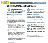
able to determine the harmonics of the motor and monitor
when the values have changed, predicting a problem with the
machinery before a failure occurs. The Music Pitch Analysis
Demo uses an accelerometer to detect the harmonics from a
vibration. This can be quickly demonstrated using tuning forks
with the TRIAX board. For example, striking an “A” tuning fork
and placing it next to the TRIAX board, the highest amplitude
frequency recognized by the accelerometer would be 440 Hz
and the check box corresponding to an “A” would be selected.
See Figure 8.
Figure 8. Music Pitch Analysis Demo
Accelerometers can also be used to detect the rotational
vibration (RV) of hard disk drives (HDDs). When the RV
characteristics of an operational HDD becomes too large or
contains certain spectral content, the drive’s performance is
often compromised. Poor seek times, read/write errors, and
lost data can be the result of excessive RV. The
accelerometer detects the RV and enables the HDD to adjust
the drive for better operation.
Shock Measurement
Shock Applications range from Black Boxes and Event
Data Recorders, Hard Disk Drive Protection, and Shipping &
Handling Monitors to record shock levels experienced during
transportation of fragile products.
The Shock Detection Module provides a simple
demonstration of using the accelerometer to not only detect
shock, but also to detect which axis the shock occurred. This
is a stand-alone module. Therefore, once the Shock Detection
Module is selected, the serial cable can be disconnected for
the demonstration. The TRIAX board beeps once when the
impact occurs in the X-axis, twice when it occurs in the Y-axis
and three times when the impact occurs in the Z-axis.
This demonstration can be further enhanced by adding
software to sample the signal for shock recognition features
that would determine different actions for different types of
shock. The accelerometers available on the TRIAX board are
±1.5g, therefore the shock conditions are anything above 1g.
For many applications, a higher g-range is necessary.
Freescale offers accelerometers from ±1.5g all the way up to
±250g. For applications requiring a higher g range, there are
devices available.
Circuit Description
The TRIAX board is used to demonstrate many different
applications; therefore it was not optimally designed for one
specific application. The basic components are three low g
accelerometers, a microcontroller, serial communication
circuitry, EEPROM for data collection, and a piezohorn. This
TRIAX board displays the three-axis solution with three
accelerometers in the 16-pin SOIC. The microcontroller
selected was the MC68908KX8. It was selected because it
has an SCI required for the serial communication, four 8-bit
ADC channels, three of which are required for the three
accelerometer voltage outputs, and 8 Kb of on-chip, in-circuit
programmable FLASH memory that is used for calibration
data and remembering which software module was last run
using the PC.
Figure 9. MC68HC908KX8 PDIP and SOIC
Pin Assignments
Calibration
The zero g offset for the MMA1260D and the MMA2260D
accelerometers are specified with a typical value of 2.5 V ±.
Follow these steps to determine the calibration values.
Write down the A/D values for the X, Y, and Z outputs at 0g
and 1g:
1. Start the RAW data software module.
2. Enter the A/D values for X, Y, and Z when experiencing
0g and 1g of static acceleration. Refer to Table 1 to see
how to position the TRIAX boards to achieve the correct
values.
3. Write the value in a similar table as show in Figure 10.
4. Close the RAW data module.
5. Start the CALIBRATE software module.
6. Fill in the A/D values that were determined. See
Figure 11 for typical values.
7. Press the Calibration button.
8. Close the CALIBRATE software module.
Figure 10. Calibration Data Table
PTB7/(OSC2)/RST
V
DD
PTA4/KBD4
PTA3/KBD3/TCH1
PTA2/KBD2
/TCH0
PTB4/RXD
PTB6/(OSC1
PTB5/TXD
PTB3/AD3
VSS
PTA1/KBD1
PTA0/KBD0
IRQ1
PTB0/AD0
PTB2/AD2
PTB1/AD1
8
2
3
4
5
7
6
9
16
15
14
13
12
10
11
1
0g
1g
X AXIS Y AXIS Z AXIS
AN1986
Sensors
Freescale Semiconductor 5
The table in Figure 11 provides typical values. These
typical values enable the TRIAX board to work with the PC
software; however, accurately calibrating the accelerometers
is necessary to find the exact values for the board. Use these
values as a reference to enure the values that were obtained
using the RAW DATA module were gathered by holding the
board correctly.
Figure 11. Typical A/D Values for Calibrating the
TRIAX Board
Serial Connection and PC Operation
The TRIAX boards have serial circuitry and a DB9
connector for serial communication with the PC. The
microcontroller is programmed with different modules that
transmit data to the PC at different speeds and with different
accelerometer data, depending on the current module
selected with the PC interface.
To set up the system for PC operation, follow these steps:
1. Connect the TRIAX board to the PC using a DB9
male/female serial cable.
2. Launch the PC Software Executable program
TRIAX3.2.exe.
3. Slide the TRIAX board switch in the On position.
4. Confirm that a data handshake occurs when the
piezohorn beeps.
Before any module is started, a handshake occurs with the
PC and the TRIAX board. If S2 is pressed after Reset and
before the Handshake, then the system goes into Sample
Mode (X&Y 100x/s 40.96s).
A Handshake occurs by the microcontroller waiting for the
character R. When recognized, it responds with a character
that represents the version of the microcontroller software
available. For Version 2 (TRIAX07.asm), the microcontroller
returns an N. (i.e., M for TRIAX06.asm) and it beeps once.
When the connection between the TRIAX board and the PC is
established, the microcontroller waits for a character from the
PC. Each character received tells the microcontroller which
firmware module should be run. Then the selected firmware
module will continue to run until the microcontroller is
restarted.
Table 1. TRIAX Board Calibration Positions
0g
X at 0g Place the TRIAX board on a flat surface so the components are face up and the battery is
resting on the table.
Y at 0g Place the TRIAX board on a flat surface so the components are face up and the battery is
resting on the table.
Z at 0g Hold the TRIAX board on its side so that the serial cable is at the top. The TRIAX board is
perfectly horizontal when X has a maximum voltage without being shaken.
1g
X at 1g Hold the TRIAX board perpendicular so that the serial cable is at the top. The TRIAX
board is perfectly horizontal when Y has a maximum voltage without being shaken.
Y at 1g Hold the TRIAX board on its side so that the serial cable is at the top. The TRIAX board is
perfectly horizontal when X has a maximum voltage without being shaken.
Z at 1g Place the TRIAX board on a flat surface so the components are face up and the battery is
resting on the table.
0g
1g
X AXIS Y AXIS Z AXIS
128 128 128
189 189 189
AN1986
Sensors
6 Freescale Semiconductor
Stand Alone Operation
There is a feature on the TRIAX board that does not require
the PC. It allows two demonstrations to run. The first
demonstration that is always available in stand-alone
operation is the free-fall demonstration. The second
demonstration is the most recently used stand-alone
application that was selected using the PC software.
To run the free-fall demonstration without the PC
connected, turn the TRIAX board on while holding the
pushbutton. Continue holding the pushbutton for 10 seconds.
When the piezohorn sounds, the Free-fall Module is activated.
To allow the user to drop and catch the TRIAX board, it
sounds the piezohorn when the free-fall conditions are met.
The Free-fall Module continues to run until the board is
restarted.
To run the most recently used stand-alone operation, hold
down the pushbutton while turning on the TRIAX board. For
example, if the battery saver demo was the last module run,
then you will be able to run the battery saver module or the
Free-fall Module. To run the battery saver module, hold the
pushbutton while turning on the TRIAX board and then quickly
release the pushbutton. The piezohorn automatically starts
beeping to signal that movement is detected. The battery
saver module continues to run until the board is restarted.
SUMMARY
There are many new applications being designed using
accelerometers. The TRIAX board is designed to demonstrate
some of the general accelerometer applications. This
application note describes these applications using the
software programs available for the TRIAX board. After
reading this application note, the user will be able to use the
TRIAX board to demonstrate the existing accelerometer
applications and be able to demonstrate their own design
ideas.
AN1986
Sensors
Freescale Semiconductor 7
NOTES
How to Reach Us:
Home Page:
www.freescale.com
E-mail:
USA/Europe or Locations Not Listed:
Freescale Semiconductor
Technical Information Center, CH370
1300 N. Alma School Road
Chandler, Arizona 85224
+1-800-521-6274 or +1-480-768-2130
Europe, Middle East, and Africa:
Freescale Halbleiter Deutschland GmbH
Technical Information Center
Schatzbogen 7
81829 Muenchen, Germany
+44 1296 380 456 (English)
+46 8 52200080 (English)
+49 89 92103 559 (German)
+33 1 69 35 48 48 (French)
Japan:
Freescale Semiconductor Japan Ltd.
Headquarters
ARCO Tower 15F
1-8-1, Shimo-Meguro, Meguro-ku,
Tokyo 153-0064
Japan
0120 191014 or +81 3 5437 9125
Asia/Pacific:
Freescale Semiconductor Hong Kong Ltd.
Technical Information Center
2 Dai King Street
Tai Po Industrial Estate
Tai Po, N.T., Hong Kong
+800 2666 8080
For Literature Requests Only:
Freescale Semiconductor Literature Distribution Center
P.O. Box 5405
Denver, Colorado 80217
1-800-441-2447 or 303-675-2140
Fax: 303-675-2150
AN1986
Rev.1
05/2005
Information in this document is provided solely to enable system and software
implementers to use Freescale Semiconductor products. There are no express or
implied copyright licenses granted hereunder to design or fabricate any integrated
circuits or integrated circuits based on the information in this document.
Freescale Semiconductor reserves the right to make changes without further notice to
any products herein. Freescale Semiconductor makes no warranty, representation or
guarantee regarding the suitability of its products for any particular purpose, nor does
Freescale Semiconductor assume any liability arising out of the application or use of any
product or circuit, and specifically disclaims any and all liability, including without
limitation consequential or incidental damages. “Typical” parameters that may be
provided in Freescale Semiconductor data sheets and/or specifications can and do vary
in different applications and actual performance may vary over time. All operating
parameters, including “Typicals”, must be validated for each customer application by
customer’s technical experts. Freescale Semiconductor does not convey any license
under its patent rights nor the rights of others. Freescale Semiconductor products are
not designed, intended, or authorized for use as components in systems intended for
surgical implant into the body, or other applications intended to support or sustain life,
or for any other application in which the failure of the Freescale Semiconductor product
could create a situation where personal injury or death may occur. Should Buyer
purchase or use Freescale Semiconductor products for any such unintended or
unauthorized application, Buyer shall indemnify and hold Freescale Semiconductor and
its officers, employees, subsidiaries, affiliates, and distributors harmless against all
claims, costs, damages, and expenses, and reasonable attorney fees arising out of,
directly or indirectly, any claim of personal injury or death associated with such
unintended or unauthorized use, even if such claim alleges that Freescale
Semiconductor was negligent regarding the design or manufacture of the part.
Freescale™ and the Freescale logo are trademarks of Freescale Semiconductor, Inc.
All other product or service names are the property of their respective owners.
© Freescale Semiconductor, Inc. 2005. All rights reserved.
  • Page 1 1
  • Page 2 2
  • Page 3 3
  • Page 4 4
  • Page 5 5
  • Page 6 6
  • Page 7 7
  • Page 8 8

NXP MMA6261Q User guide

Type
User guide
This manual is also suitable for

Ask a question and I''ll find the answer in the document

Finding information in a document is now easier with AI