Page is loading ...

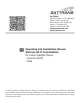
Thuraya IP Commander
Operating Instructions
Version 4.0

SRT Wireless LLC is thesole distributor oftheThurayaIPCommander.
ii
SRTWireless, LLC, Davie, FL 33314
© 2015 by SRTWireless, LLC. All Rights Reserved.
Published 2015
Printed in the United States of America
is atrademark of SRTWireless, LLC in the United States and other countries.
Wi-Fi®, Wi-Fi Alliance®, the Wi-Fi CERTIFIED™ logo, the Wi-Fi logo, WMM® and
the Wi-Fi ZONE logo are registered trademarks of the Wi-Fi Alliance; Wi-Fi
CERTIFIED™, the Wi-Fi Alliance logo, Wi-Fi ZONE, WPA, WPA2, Wi-Fi
PROTECTED SET-UP and Wi-Fi Protected Set-up logo are trademarks of the Wi-Fi
Alliance. IEEE Std 802.11-2007 is atrademark of the Institute of Electrical and Electronics
Engineers, Inc. Ethernet is aregistered trademark of Ethernet Alliance, Inc. Adobe,
Acrobat, Adobe Reader, and Flash are trademarks or registered trademarks of Adobe Sys-
tems, Inc. Microsoft, Windows, and .NET are trademarks or registered trademarks of
Microsoft Corporation in the United States and other countries. Thuraya is aregistered
trademark of Thuraya Satellite Telecommunications Company. Ethernet is aregistered trade-
mark of Ethernet Alliance, Inc. Apple, OSX, and Safari are registered trademarks of Apple
Inc., registered in the U.S. and other countries. Mozilla and Firefox are registered trade-
marks of the Mozilla Foundation. 3Mand Scotch are trademarks or registered trademarks
of 3MCompany. Google Chrome is atrademark of Google Inc. Linux® is the registered
trademark of Linus Torvalds in the U.S. and other countries.
All other trademarks or registered trademarks of products mentioned in this document are
the property of their respective owners.
Technical Support: support@srtrl.com
Version Date Change Description
1.0 12/1/2014 Initial Release
2.0 10/13/2015 Update logos, update user interface
920-00299 -10/13/2015

Table of Contents
i
i
Thuraya IPCommander Terminal i
Table of Contents iii
List of Figures iv
List of Tables v
Safety Information vi
Warning Symbols vi
Warnings for the Thuraya IP Commander and Antenna vi
1. Introduction 1
Computer and Local Area Network Configuration 2
Network Configuration 2
Ethernet Switches and Hubs 3
Computers 3
Microsoft Windows 7 3
Microsoft Windows XP 4
Apple® OSX® (vers. 10.6.8 and newer) 5
Other Computing Hardware 5
2. Install Your New IPCommander System 6
Front Panel Controls 7
Equipment Setup 8
Physical Placement of the IPCommander Enclosure 9
Install SIMCard 12
Antenna Installation Guidelines 13
Magnetic Mount Antenna Installation Instructions 13
Other Mounting Options 14
Coaxial Cable Bending Radius 14
Coaxial Cable Protection 14
Servicing the Antenna Enclosure 14
Secure the Transmission Line and Attach to the Antenna and the
IPCommander 15
Thuraya Handset Operation 15
Use the Handset to Control the Modem 15
Handset Status Display 16
SRT Wireless LLC is thesole distributor ofproducts for SR Technologies, Inc.
iii

SRT Wireless LLC is thesole distributor ofproducts for SR Technologies, Inc.
iv
List of Figures
Figure 1: Direct Connection of Laptop and IPCommander 2
Figure 2: Connecting Laptop and IPCommander through an Ethernet Hub/Switch 2
Figure 3: Thuraya® IPCommander System Packing Case 6
Figure 4: Thuraya IPCommander Terminal 7
Figure 5: Hook-up Diagram (numbering same as above) 9
Figure 6: IPCommander Mounting Details 11
Figure 7: Steps to Install SIMCard 12
Figure 8: Thuraya Handset Configured for Use With IPCommander 15

List of Tables
Table 1: Thuraya IPCommander Terminal Connections 7
Table 2: Open Access Panel and Install Voice and IP SIMCards 12
Table 3: Close and Seal the Access Panel 12
Table 4: Remote Control Thuraya IPCommander from Handset 16
SRT Wireless LLC is thesole distributor ofproducts for SR Technologies, Inc.
v

SRT Wireless LLC is thesole distributor ofproducts for SR Technologies, Inc.
vi
Safety Information
For your safety and protection, read this entire user guide before you attempt to use the
Thuraya IP Commander. In particular, read this safety section carefully. Keep this safety
information where you can refer to if necessary.
Warning Symbols
This section introduces the various types of warnings used in this document to alert you to
possible safety hazards.
WARNING: Potential radio frequency (RF) hazard. Where you see this
alert symbol and WARNING heading, strictly follow the warn-
ing instructions to avoid injury to eyes or other personal
injury.
WARNING: Where you see this alert symbol and WARNING heading,
strictly follow the warning instructions to avoid personal
injury or damage equipment.
DANGER: Electric shock hazard: Where you see this alert symbol and
DANGER heading, strictly follow the warning instructions to
avoid electric shock injury or death.
Warnings for the Thuraya IP Commander and Antenna
WARNING: Do not stand at the side or top of the Antenna
This device emits radio frequency energy when in the transmit
mode. To avoid injury, do not place head or other body parts
at the side or top of the Thuraya antenna when system is oper-
ational. Maintain a distance of one meter away from those
areas of the Thuraya antenna when energized.
WARNING: In the vicinity of blasting work and in explosive envir-
onments
Never use the Thuraya IP Commander where blasting work is
in progress. Observe all restrictions and follow any reg-
ulations or rules. Areas with apotentially explosive envir-
onment are often, but not always, clearly marked. Do not use
the Thuraya IP Commander while at a fuel filling station. Do
not use near fuel or chemicals.

WARNING: Antenna
The antenna cable carries DC power. Always power the
IPCommander down prior to connecting or disconnecting the
antenna cable from either the Thuraya antenna or the
IPCommander. Do not bend or kink the antenna cable.
Keep aclear line-of-sight to the satellite. Preferably, avoid all
obstructions within three meters of the Thuraya antenna.
Obstructions less than 150 mm (six inches) in diameter can be
ignored beyond this distance.
Do not locate the antenna close to interfering signal sources
or receivers. It is recommended that no other antennas be loc-
ated within three meters of the Thuraya antenna. If there is
other equipment installed near the Thuraya IP Commander, it
is recommended to operate all equipment simultaneously and
verify there is no co-interference.
Install and use the antenna with care. SRTWireless LLC
assumes no liability for any damage caused by the antenna
falling off the vehicle or stressing the mounting base. It is the
responsibility of the customer to ensure a safe and correct
installation of the antenna. The instructions in the Installation
manual are only guidelines.
Under normal driving circumstances the magnetic force of the
magnetic mount kit for the antenna should be sufficient to hold
the antenna. However, the magnets may not be able to hold
the antenna in place, if:
•the vehicle is involved in an accident,
•the magnets are not mounted properly,
•the roof is not plain (smooth) or made of a material that will
not stick properly to the magnets,
•the speed of the vehicle is too high and/or
•the road is very bumpy.
SRT Wireless LLC is thesole distributor ofproducts for SR Technologies, Inc.
vii

SRT Wireless LLC is thesole distributor ofproducts for SR Technologies, Inc.
viii
WARNING: General
Handle your Thuraya IP Commander device with care. The
Thuraya antenna is weather resistant per IEC 60529 IP56;
however, do not submerge the unit. Avoid exposing the
Thuraya IP Commander to extreme hot or cold temperatures
outside the range -25 ºC to +55 ºC.
Avoid placing the IPCommander device close to open flames
or any source of heat.
Changes or modifications to the IPCommander device not
expressly approved by SRTWireless, LLC could void your
authority to operate this equipment.
Only use a soft damp cloth to clean the IPCommander device.
To avoid impaired performance, please ensure the unit’s
Thuraya antenna is not damaged or covered with foreign
material like paint or labeling.
WARNING: Service
User access to the interior of the system units is prohibited.
Only atechnician authorized by SRTWireless, LLC may per-
form service -failure to comply with this rule will void the war-
ranty.
Do not service or adjust alone. Do not attempt internal service
or adjustments unless another person, capable of rendering
first aid resuscitation, is present.
Operating personnel must not remove equipment covers. Com-
ponent replacement and internal adjustment must be made by
qualified maintenance personnel. Do not replace components
with the power cable connected. Under certain conditions,
dangerous voltages may exist even with the power cable
removed. To avoid injuries, always disconnect power and dis-
charge circuits before touching them.
Do not attempt to disassemble the Thuraya antenna or
IPCommander device. The unit does not contain consumer-
serviceable components. Only qualified service personnel may
install or repair equipment.

WARNING: Accessories
Use SRTWireless LLC approved accessories only. Use of
non-approved accessories may result in loss of performance,
damage to the IP Commander, fire, electric shock or injury.
WARNING: Connecting Devices
Never connect incompatible devices to the Thuraya IP Com-
mander. When connecting the Thuraya IP Commander to any
other device, read this User Manual for detailed safety instruc-
tions.
DANGER: Pacemakers
The various brands and models of cardiac pacemakers avail-
able exhibit a wide range of immunity levels to radio signals.
Therefore, people who wear a cardiac pacemaker and who
want to use the Thuraya IP Commander should seek the advice
of their cardiologist. If, as a pacemaker user, you are still con-
cerned about interaction with the Thuraya IP Commander, we
suggest you follow these guidelines:
• Maintain a distance of 20 cm from the Wi-Fi antenna and
your pacemaker;
• Maintain a distance of one meter from the Thuraya antenna
front and sides and your pacemaker;
•Refer to your pacemaker product literature for information
on your particular device.
If you have any reason to suspect that interference is taking
place, turn off your Thuraya IP Commander immediately.
DANGER: Hearing Aids
Most new models of hearing aids are immune to radio fre-
quency interference from satellite terminals that are more than
2meters away. Many types of older hearing aids may be sus-
ceptible to interference, making it very difficult to use them near
aterminal. Should interference be experienced, maintain addi-
tional separation between you and the IP Commander.
DANGER: Electrical Storms
Operation of the Thuraya IP Commander during electrical
storms may result in severe personal injury or death.
SRT Wireless LLC is thesole distributor ofproducts for SR Technologies, Inc.
ix

SRT Wireless LLC is thesole distributor ofproducts for SR Technologies, Inc.
x
This page is intentionally blank

1. Introduction
Thank you for purchasing the Thuraya® IPCommander terminal, a product of
SRTWireless, LLC,and hereinafter referred to as the IPCommander.The
IPCommander gives you instant access to the Internet anywhere you can “see” a
Thuraya satellite. With the addition of a multi-port switch, you can use your
IPCommander to set up a small network for wired devices, as well as wireless con-
nections through its standard Wi-Fi® system.
This guide provides instructions for installing the IPCommander device and its antenna
Instructions for the operation of the IPCommander device are found in the Quick Start
Guide (SRTWpart number 920-00276), which has been provided in printed form, and the
User Guide (SRTW part number 920-00275), which has been provided on the supplied
Document-Media CD.
1
1. Introduction

1. Introduction
2
Computer and Local Area Network Configuration
Your 10/100 MB/sec local area network (LAN) can be set up for wired, wireless, or both.
Without going into great detail, local area network setup is exactly the same as with a
wired/wireless router. Along with full 802.11 b, g, and nWi-Fi support, wired networks
are supported with DHCP (dynamic host control protocol)services. In other words, as
long as your PC is set up to connect to a network using DHCP, you can connect hubs,
switches, and up to 254 peripherals (printers, other PCs, etc.) to the network, beginning
with the Ethernet port on the IPCommander.
Network Configuration
In basic terms, the IPCommander can connect to a network in one of two ways:
•Direct connection between the Laptop PC and the IPCommander (single user).
See Figure 1.
Connect Ethernet Port of Laptop
Directly to Ethernet Port of IP Commander
Thuraya
Satellite
To Thuraya
Antenna
10/100 MB/sec
Figure 1: Direct Connection of Laptop and IPCommander
• Connect the IPCommander and Laptop PC through an Ethernet hub or switch
(multiple users). See Figure 2.
To other
network clients
To Thuraya
IP Commander
10/100 MB/sec
Ethernet Hub/Switch
Thuraya
Satellite
To Laptop PC
running Web
Browser
Figure 2: Connecting Laptop and IPCommander through an Ethernet Hub/Switch

Ethernet Switches and Hubs
By connecting the designated input port of a five-port Ethernet hub or switch to the Eth-
ernet (RJ-45)connector on the IPCommander front panel, four TCP/IP compatible net-
work devices, such as switches, printers, and computers, can be added to the local area
network. If required, the devices should configure themselves using the IPCommander
DHCPserver functions.
NOTE: Bandwidth on the IPCommander satellite link is limited to a maximum of 384
kbps uplink and 444 kbps downlink. Please avoid streaming large files
(movies, etc.) through the satellite, as the connection will quickly saturate,
slowing down the network for you, and any other users that may be sharing
your satellite connection via the local area network.
Computers
In order to communicate with the IPCommander,and to become amember of the
IPCommander network, computers must be set up to be able to receive network con-
figuration information from the DHCPserver on the IPCommander device. There are
some differences in configuration between Microsoft® Windows XP and Windows 7
(Windows Vista setup is very similar to that of Windows 7), which are outlined below.
Microsoft Windows 7
NOTE: The only web browsers that have been tested are Microsoft Internet
Explorer®, versions 7 and newer, and recent versions of the Mozilla® Fire-
fox® web browser. Other browsers may work, but have not been tested or cer-
tified by SRTWireless.
1. Connect an Ethernet cable between the computer and the Ethernet port on the
IPCommander (or through an Ethernet switch, which in turn is connected to the
IPCommander).
2. Click the Start button and then the Control Panel icon. Click the Network and Sharing
Center icon. Then click the Local Area Connection icon.
3. Click the Properties icon in the Local Area Connection Status window. This opens the
Local Area Connection Properties window.
4. Make sure the box next to Internet Protocol Version 4 (TCP/IPv4) is checked. Highlight
Internet Protocol (TCP/IPv4),and click the Properties button.
3
1. Introduction

1. Introduction
4
5. Select Obtain an IP address automatically.Once the new window appears, click the OK
button. Click the OK button again to complete the PC configuration.
6. Power-up the IPCommander and link with the Thuraya satellite.
7. Launch your preferred web browser and enter the URL
http://www.192.168.1.254. You should see alogin screen to the
IPCommander.The default username is admin,and the default password is
admin.
8. If this screen displays within a reasonable amount of time, the network connection has
been successfully established, and no network configuration settings need to be
changed.
Microsoft Windows XP
NOTE: Microsoft ceased support for Windows XP in on8April 2014. Microsoft has
stated that they are not providing any security patches, bug fixes, or support
beyond 8 April 2014. If you are still running Windows XP, you are encour-
aged to upgrade to Microsoft Windows 7 at your earliest convenience. At the
time this manual was published, Microsoft Windows 8 has not been tested or
certified by SRTWireless.
1. Connect an Ethernet cable between the computer and the Ethernet port on the
IPCommander (or through an Ethernet switch, which in turn is connected to the
IPCommander).
2. Click the Start button and then the Control Panel icon. Click the Network and Internet
Connections icon. Then click the Network Connections icon.
3. Select the Local Area Connection icon for the applicable Ethernet adapter (usually it is
the first Local Area Connection listed). Double-click the Local Area Connection.Click
the Properties button.
4. Make sure the box next to Internet Protocol (TCP/IP) is checked. Highlight Internet Pro-
tocol (TCP/IP),and click the Properties button.
5. Select Obtain an IP address automatically.Once the new window appears, click the OK
button. Click the OK button again to complete the PC configuration.
6. Power-up the IPCommander and link with the Thuraya satellite.
7. Launch your preferred web browser and enter the URL
http://www.192.168.1.254.The default username is admin,and the default
password is admin.

8. You should see alogin screen to the IPCommander. If this screen displays within a
reasonable amount of time, the network connection has been successfully established,
and no network configuration settings need to be changed.
Apple® OSX® (vers. 10.6.8 and newer)
NOTE: While this configuration has not been tested by SRT Wireless, there is no obvi-
ous reason why web browsers, such as Apple Safari®, Mozilla Firefox, or
Google Chrome™ should not function properly on Apple Macintosh® com-
puter hardware.
Unless you have changed your Apple computer’s default network settings to use a static IP
address, the Mac OS X default network configuration is DHCP, which is the preferred set-
ting for communicating with the IPCommander.
1. Connect an Ethernet cable between the computer and the Ethernet port on the
IPCommander (or through an Ethernet switch, which in turn is connected to the
IPCommander).
2. Power-up the IPCommander and link with the Thuraya satellite.
3. Launch your preferred web browser and enter the URL
http://www.192.168.1.254.The default username is admin,and the default
password is admin.
4. You should see alogin screen to the IPCommander. If this screen displays within a
reasonable amount of time, the network connection has been successfully established,
and no network configuration settings need to be changed.
Other Computing Hardware
Web browsers running on computing devices using other operating systems, such as
Linux®, or web browsers running on many popular tablet devices should also work cor-
rectly, but have not been tested or certified by SRTWireless.
5
1. Introduction

2. Install Your New IPCommander System
6
2. Install Your New IPCommander System
Open the packing case. Review the packing diagram located in the indentation in the lid of
the packing case to confirm the contents. See Figure 3 below.
Figure 3: Thuraya® IPCommander System Packing Case
The system is shipped in a custom shipping box, which contains a Thuraya IP Com-
mander radio, a SpaceCom® antenna with a 10-foot (3 meter) RF cable, awired Thuraya
handset, two Wi-Fi antennas, Ethernet (RJ-45)cable, aDC power cable, an AC power sup-
ply, and documentation/product licensing media.
A ruggedized Pelican® case (optional at extra cost, shown above) makes it easy for mobile
users to safely transport their IPCommander system wherever it needs to go.

Front Panel Controls
Figure 4: Thuraya IPCommander Terminal
Item Description
❶Wi-Fi Antenna Port
(SMA) Connect aWi-Fi antenna to permit use as awireless access point.
❷SpaceCom Antenna Port Connects theSpaceCom satellite antenna to the Thuraya
IPCommander.
❸Handset Connector
Connects aspecially-configured Thuraya telephone handset for
making calls from the IPCommander,and performs basic controls
on the IPCommander.
❹Power Input Connects to AC-to-DC Power Supply, or avehicular power cable.
❺RJ-45 (Ethernet)
Connector
Connects the IPCommander to a10/100 MB/sec local area net-
work.
❻Status Indicator Panel
Seven indicator lights show system status.
SUP:Power supply is connected
ON:IPCommander is powered on
ACT:Activity on the satellite link
SAT:Satellite antenna status
GPS:GPSstatus
ANT:Transmit antenna status
LAN:Local Area Network status
❼Power/Reset Button
Quickly press and release topower up the Thuraya
IPCommander.Press and hold for several seconds to reboot or
completely power-down the unit.
Table 1: Thuraya IPCommander Terminal Connections
7
2. Install Your New IPCommander System

2. Install Your New IPCommander System
8
Equipment Setup
1. Carefully attach the “rubber duck”whip antenna to the SMA connector (item ❶). The
antenna is hinged, which permits you to orient it vertically.
CAUTION: The SMA connector is very fragile. Tighten connector “finger tight.”Do
not use tools to tighten.
2. Uncoil the 10-foot (3-meter)RFcable. Connect one side to the TNC connector on the
Thuraya IPCommander (item ❷above). Connect the other side to the
TNCconnector on the Thuraya SpaceCom antenna. Place the antenna outside with a
full view of the sky.
3. Connect the handset (cable removed from photo for clarity) to the handset port on the
Thuraya IPCommander (item ❸above).
4. Connect the locking end of the RJ-45 Ethernet cable to the Thuraya IPCommander
(item ❺above), and the other to your network (switch, router, or a computer).
5. Connect the locking end of the power supply to the Thuraya IPCommander (item ❹
above). Connect the ACpower cord (removed from photo for clarity) to the power
supply and plug into a standard wall outlet (100-240 VAC, 50/60 Hz).1
6. Briefly press the power button (item ❼above) to power up the unit.
1An automotive-style DCpower cord is also provided with the Thuraya IPCommander.It has
the same locking connector as the AC/DCpower supply.

❶
❷
❸❹
❺
❷
❷
❷
❷
❷
❷
❷
Figure 5: Hook-up Diagram (numbering same as above)
Physical Placement of the IPCommander Enclosure
CAUTION: The Thuraya IPCommander and its accessories should be secured
whenever the vehicle is moving to prevent damage to the vehicle or harm
to its occupants in the event of a sudden stop or collision. When operating
from afixed location, the Thuraya IPCommander device can be placed
almost anywhere, but should be kept away from direct sunlight. Space
should be provided around the unit in order to more effectively exhaust
heat generated from within the device.
For permanent installations, the Thuraya IPCommander may be small enough to be
mounted under the dashboard or center console of some vehicles. Mounting hardware
(screws, bolts, brackets) are not provided.
Four threaded mounting points are provided on the top of the enclosure, and two additional
mounting points are provided on the left and right sides of the enclosure. Hardware is
M6X1.0. This permits you to fabricate a mounting bracket for more permanent install-
9
2. Install Your New IPCommander System

2. Install Your New IPCommander System
10
ations. A dimensioned drawing (Figure 6) is provided to assist you in fabricating a mount-
ing bracket.
NOTE: The M6X1.0 bolts used to attach mounting hardware to the Thuraya
IPCommander enclosure need to be short enough so that after taking into
account the thickness of the bracket and any washers, the maximum per-
missible length going into the threaded hole is 0.160 inches (about 3/16 inch).
The enclosure is aluminum; do not overtighten the bolts, as it may strip the
threads.
Because of its small size, and ability to be controlled with aweb browser, the Thuraya
IPCommander enclosure can be mounted almost anywhere, in plain sight, or stashed
away, out of sight. The only physical control is the Power/Reset button. If you need to
reboot the device, take the Thuraya handset that is wired to the IPCommander and enter
###7 on the handset’s keypad.
As stated in the previous section, care must be taken to route the rf coaxial cable so that it
either does not go through a vehicle’s door or hatch (being crushed by the door seals), or if
there is no alternative, ensure that the cable goes across the softest and most flexible part of
the seal.
/