Page is loading ...

2011/8/172011/8/17
IMBA-G410 ATX Motherboard
Page i
IEI Technology Corp.
User Manual
MODEL:
IMBA-G410
ATX Motherboard for Intel® Core™2 Duo
/
Quad CPU,
800/1066/1333 MHz FSB, DDR3, VGA, LAN, SATA 3Gb/s,
PCIe x16, PCIe x4, PCI, USB, HD Audio, RoHS Compliant
Rev. 1.01 – 17 August, 2011


2011/8/172011/8/17
IMBA-G410 ATX Motherboard
Page iii
Copyright
COPYRIGHT NOTICE
The information in this document is subject to change without prior notice in order to
improve reliability, design and function and does not represent a commitment on the part
of the manufacturer.
In no event will the manufacturer be liable for direct, indirect, special, incidental, or
consequential damages arising out of the use or inability to use the product or
documentation, even if advised of the possibility of such damages.
This document contains proprietary information protected by copyright. All rights are
reserved. No part of this manual may be reproduced by any mechanical, electronic, or
other means in any form without prior written permission of the manufacturer.
TRADEMARKS
All registered trademarks and product names mentioned herein are used for identification
purposes only and may be trademarks and/or registered trademarks of their respective
owners.

iv8/17/2011158
IMBA-G410 ATX Motherboard
Page iv
Table of Contents
1 INTRODUCTION........................................................................................................... 1
1.1 INTRODUCTION........................................................................................................... 2
1.2 BENEFITS ................................................................................................................... 2
1.3 FEATURES................................................................................................................... 3
1.4 CONNECTORS ............................................................................................................. 4
1.5 DIMENSIONS............................................................................................................... 5
1.6 DATA FLOW................................................................................................................ 6
1.7 TECHNICAL SPECIFICATIONS ...................................................................................... 7
2 PACKING LIST .............................................................................................................. 9
2.1 ANTI-STATIC PRECAUTIONS...................................................................................... 10
2.2 UNPACKING PRECAUTIONS....................................................................................... 10
2.3 PACKING LIST............................................................................................................11
2.4 OPTIONAL ITEMS...................................................................................................... 12
3 CONNECTORS............................................................................................................. 14
3.1 PERIPHERAL INTERFACE CONNECTORS..................................................................... 15
3.1.1 Layout .............................................................................................................. 15
3.1.2 Peripheral Interface Connectors ..................................................................... 16
3.1.3 External Interface Panel Connectors............................................................... 17
3.2 INTERNAL PERIPHERAL CONNECTORS ...................................................................... 17
3.2.1 Audio Connector .............................................................................................. 17
3.2.2 CPU Fan Connector........................................................................................ 18
3.2.3 System Fan Connectors.................................................................................... 19
3.2.4 CPU Power Input Connector........................................................................... 20
3.2.5 Digital I/O Connector...................................................................................... 21
3.2.6 Front Panel Connector .................................................................................... 21
3.2.7 IDE Connector................................................................................................. 22
3.2.8 Infrared Interface Connector........................................................................... 24
3.2.9 Memory Slots ................................................................................................... 24
3.2.10 PCIe Power Input Connector......................................................................... 25

2011/8/172011/8/17
IMBA-G410 ATX Motherboard
Page v
3.2.11 Power Connector............................................................................................ 26
3.2.12 RS-232 Serial Port Connectors...................................................................... 27
3.2.13 RS-232/422/485 Serial Port Connector......................................................... 28
3.2.14 SATA Drive Connectors ................................................................................. 28
3.2.15 SMBus Connector .......................................................................................... 29
3.2.16 SPDIF Connector........................................................................................... 30
3.2.17 SPI Flash Connector...................................................................................... 31
3.2.18 TPM Connector.............................................................................................. 31
3.2.19 USB Connectors............................................................................................. 32
3.3 EXTERNAL PERIPHERAL INTERFACE CONNECTOR PANEL ......................................... 33
3.3.1 Audio Connectors............................................................................................. 34
3.3.2 Keyboard/Mouse Connector ............................................................................ 34
3.3.3 LAN Connectors............................................................................................... 35
3.3.4 Parallel Port Connector .................................................................................. 36
3.3.5 Serial Port Connector (COM1) ....................................................................... 37
3.3.6 USB Connectors............................................................................................... 38
3.3.7 VGA Connector................................................................................................ 38
4 INSTALLATION........................................................................................................... 40
4.1 ANTI-STATIC PRECAUTIONS...................................................................................... 41
4.2 INSTALLATION CONSIDERATIONS.............................................................................. 41
4.3 BASIC INSTALLATION ............................................................................................... 43
4.3.1 CPU Installation.............................................................................................. 43
4.3.2 Cooling Kit Installation ................................................................................... 46
4.3.3 DIMM Installation........................................................................................... 48
4.3.4 Motherboard Installation................................................................................. 48
4.4 JUMPER SETTINGS .................................................................................................... 49
4.4.1 AT/ATX Power Select Jumpers ........................................................................ 49
4.4.2 Clear CMOS Jumper........................................................................................ 50
4.4.3 COM 2 Function Select Jumper....................................................................... 51
4.4.4 CompactFlash® Setup..................................................................................... 52
4.4.5 CF Voltage Select Jumper................................................................................ 53
4.4.6 USB Power Select Jumpers.............................................................................. 53
4.5 INTERNAL PERIPHERAL DEVICE CONNECTIONS........................................................ 54
4.5.1 SATA Drive Connection ................................................................................... 54

vi8/17/2011158
IMBA-G410 ATX Motherboard
Page vi
4.5.2 Dual RS-232 Cable with Slot Bracket.............................................................. 56
4.6 EXTERNAL PERIPHERAL INTERFACE CONNECTION ................................................... 57
4.6.1 Audio Connector .............................................................................................. 57
4.6.2 PS/2 Keyboard and Mouse Connection........................................................... 58
4.6.3 LAN Connection............................................................................................... 59
4.6.4 Parallel Device Connection............................................................................. 60
4.6.5 Serial Device Connection ................................................................................ 61
4.6.6 USB Device Connection................................................................................... 62
4.6.7 VGA Monitor Connection ................................................................................ 63
4.7 SOFTWARE INSTALLATION ........................................................................................ 64
5 BIOS.............................................................................................................................. 65
5.1 INTRODUCTION......................................................................................................... 66
5.1.1 Starting Setup................................................................................................... 66
5.1.2 Using Setup...................................................................................................... 66
5.1.3 Getting Help..................................................................................................... 67
5.1.4 Unable to Reboot After Configuration Changes.............................................. 67
5.2 MAIN BIOS MENU................................................................................................... 67
5.3 STANDARD BIOS FEATURES .................................................................................... 70
5.3.1 System Information .......................................................................................... 71
5.4 ADVANCED BIOS FEATURES .................................................................................... 72
5.4.1 SATA Configuration ......................................................................................... 72
5.4.2 Onboard Devices Configuration...................................................................... 73
5.4.3 Console Redirection Configuration ................................................................. 81
5.5 ADVANCED CHIPSET FEATURES................................................................................ 83
5.6 BOOT CONFIGURATION FEATURES............................................................................ 86
5.6.1 Boot Settings Configuration............................................................................. 87
5.6.2 Boot Device Priority........................................................................................ 89
5.6.3 SubDevice Boot Configuration........................................................................ 90
5.7 POWER MANAGEMENT FEATURES............................................................................ 90
5.7.1 APM Configuration.......................................................................................... 92
5.8 PNP/PCI CONFIGURATIONS...................................................................................... 94
5.9 PC HEALTH STATUS ................................................................................................. 96
5.9.1 PC Health Info................................................................................................. 96
5.10 BIOS SECURITY FEATURES .................................................................................... 98

2011/8/172011/8/17
IMBA-G410 ATX Motherboard
Page vii
5.10.1 System Configuration Lock............................................................................ 99
5.10.2 HDD Security............................................................................................... 100
A BIOS OPTIONS ......................................................................................................... 101
B TERMINOLOGY........................................................................................................ 104
C ONE KEY RECOVERY.............................................................................................. 108
C.1 ONE KEY RECOVERY INTRODUCTION .................................................................... 109
C.1.1 System Requirement .......................................................................................110
C.1.2 Supported Operating System..........................................................................111
C.2 SETUP PROCEDURE FOR WINDOWS.........................................................................112
C.2.1 Hardware and BIOS Setup.............................................................................112
C.2.2 Create Partitions............................................................................................113
C.2.3 Install Operating System, Drivers and Applications......................................116
C.2.4 Build-up Recovery Partition...........................................................................117
C.2.5 Create Factory Default Image .......................................................................119
C.3 SETUP PROCEDURE FOR LINUX.............................................................................. 124
C.4 RECOVERY TOOL FUNCTIONS ................................................................................ 127
C.4.1 Factory Restore............................................................................................. 129
C.4.2 Backup System............................................................................................... 130
C.4.3 Restore Your Last Backup.............................................................................. 131
C.4.4 Manual .......................................................................................................... 132
C.5 OTHER INFORMATION............................................................................................ 133
C.5.1 Using AHCI Mode or ALi M5283 / VIA VT6421A Controller ...................... 133
C.5.2 System Memory Requirement........................................................................ 135
D WATCHDOG TIMER ................................................................................................ 136
E DIGITAL I/O INTERFACE....................................................................................... 139
E.1 INTRODUCTION ...................................................................................................... 140
E.2 DIO CONNECTOR PINOUTS.................................................................................... 140
E.3 ASSEMBLY LANGUAGE EXAMPLE .......................................................................... 140
F HAZARDOUS MATERIALS DISCLOSURE........................................................... 141
F.1 HAZARDOUS MATERIALS DISCLOSURE TABLE FOR IPB PRODUCTS CERTIFIED AS
ROHS COMPLIANT UNDER 2002/95/EC WITHOUT MERCURY ..................................... 142

viii8/17/2011158
IMBA-G410 ATX Motherboard
Page viii
List of Figures
Figure 1-1: IMBA-G410...................................................................................................................2
Figure 1-2: Connectors ..................................................................................................................4
Figure 1-3: Dimensions (mm)........................................................................................................5
Figure 1-4: Data Flow Diagram......................................................................................................6
Figure 3-1: Connectors and Jumpers.........................................................................................15
Figure 3-2: Audio Connector Location.......................................................................................18
Figure 3-3: CPU Fan Connector Location..................................................................................19
Figure 3-4: System Fan Connector Locations...........................................................................19
Figure 3-5: CPU Power Input Connector Location....................................................................20
Figure 3-6: Digital I/O Connector Location ................................................................................21
Figure 3-7: Front Panel Connector Location .............................................................................22
Figure 3-8: IDE Connector Location...........................................................................................23
Figure 3-9: Infrared Connector Location....................................................................................24
Figure 3-10: Memory Card Slot Locations.................................................................................25
Figure 3-11: PCIe Power Input Connector Location .................................................................25
Figure 3-12: Power Connector Location ....................................................................................26
Figure 3-13: Serial Port Connector Locations...........................................................................27
Figure 3-14: RS-232/422/485 Serial Port Connector Location..................................................28
Figure 3-15: SATA Drive Connector Locations.........................................................................29
Figure 3-16: SMBus Connector Location...................................................................................29
Figure 3-17: SPDIF Connector Location ....................................................................................30
Figure 3-18: SPI Flash Connector Location...............................................................................31
Figure 3-19: TPM Connector Pinout Location ...........................................................................32
Figure 3-20: USB Connector Pinout Locations.........................................................................33
Figure 3-21: External Peripheral Interface Connector..............................................................33
Figure 3-22: Audio Connector.....................................................................................................34
Figure 3-23: PS/2 Pinout and Configuration..............................................................................35
Figure 3-24: Parallel Port Connector Location..........................................................................37
Figure 3-25: Serial Port Pinouts..................................................................................................38
Figure 3-26: VGA Connector .......................................................................................................39

2011/8/172011/8/17
IMBA-G410 ATX Motherboard
Page ix
Figure 4-1: Intel LGA775 Socket .................................................................................................43
Figure 4-2: Remove Protective Cover.........................................................................................44
Figure 4-3: CPU Socket Load Plate.............................................................................................44
Figure 4-4: Insert the Socket LGA775 CPU................................................................................45
Figure 4-5: Cooling Kits...............................................................................................................46
Figure 4-6: Securing the Heat sink to the IMBA-G410..............................................................47
Figure 4-7: DIMM Installation.......................................................................................................48
Figure 4-8: AT/ATX Power Select Jumper Location..................................................................50
Figure 4-9: Clear BIOS Jumper Location ...................................................................................51
Figure 4-10: COM 2 Function Select Jumper Location.............................................................52
Figure 4-11: CompactFlash® Setup Jumper Location .............................................................52
Figure 4-12: LCD Voltage Selection Jumper Location..............................................................53
Figure 4-13: USB Power Select Jumper Location.....................................................................54
Figure 4-14: SATA Drive Cable Connection...............................................................................55
Figure 4-15: SATA Power Drive Connection..............................................................................56
Figure 4-16: Dual RS-232 Cable Installation..............................................................................57
Figure 4-17: Audio Connector.....................................................................................................58
Figure 4-18: PS/2 Keyboard/Mouse Connector.........................................................................59
Figure 4-19: LAN Connection......................................................................................................60
Figure 4-20: Parallel Device Connector......................................................................................61
Figure 4-21: Serial Device Connector.........................................................................................62
Figure 4-22: USB Connector........................................................................................................63
Figure 4-23: VGA Connector .......................................................................................................64
Figure C-1: IEI One Key Recovery Tool Menu ........................................................................ 109
Figure C-2: Launching the Recovery Tool.............................................................................. 113
Figure C-3: Recovery Tool Setup Menu .................................................................................. 114
Figure C-4: Command Mode..................................................................................................... 114
Figure C-5: Partition Creation Commands.............................................................................. 115
Figure C-6: Launching the Recovery Tool.............................................................................. 117
Figure C-7: System Configuration for Windows .................................................................... 117
Figure C-8: Build-up Recovery Partition................................................................................. 118
Figure C-9: Press any key to continue.................................................................................... 118
Figure C-10: Press F3 to Boot into Recovery Mode............................................................... 119
Figure C-11: Recovery Tool Menu ........................................................................................... 119
Figure C-12: About Symantec Ghost Window........................................................................ 120

x8/17/2011158
IMBA-G410 ATX Motherboard
Page x
Figure C-13: Symantec Ghost Path ......................................................................................... 120
Figure C-14: Select a Local Source Drive ............................................................................... 121
Figure C-15: Select a Source Partition from Basic Drive ...................................................... 121
Figure C-16: File Name to Copy Image to ............................................................................... 122
Figure C-17: Compress Image.................................................................................................. 122
Figure C-18: Image Creation Confirmation............................................................................. 123
Figure C-19: Image Creation Process...................................................................................... 123
Figure C-20: Image Creation Complete................................................................................... 123
Figure C-21: Press Any Key to Continue................................................................................ 124
Figure C-22: Partitions for Linux.............................................................................................. 125
Figure C-23: System Configuration for Linux......................................................................... 126
Figure C-24: Access menu.lst in Linux (Text Mode).............................................................. 126
Figure C-25: Recovery Tool Menu ........................................................................................... 127
Figure C-26: Recovery Tool Main Menu.................................................................................. 128
Figure C-27: Restore Factory Default...................................................................................... 129
Figure C-28: Recovery Complete Window.............................................................................. 129
Figure C-29: Backup System.................................................................................................... 130
Figure C-30: System Backup Complete Window ................................................................... 130
Figure C-31: Restore Backup................................................................................................... 131
Figure C-32: Restore System Backup Complete Window..................................................... 131
Figure C-33: Symantec Ghost Window ................................................................................... 132

2011/8/172011/8/17
IMBA-G410 ATX Motherboard
Page xi
List of Tables
Table 1-1: Technical Specifications..............................................................................................8
Table 2-1: Packing List.................................................................................................................12
Table 2-2: Optional Items.............................................................................................................13
Table 3–1: Internal Peripheral Connectors ................................................................................17
Table 3–2: External Peripheral Connectors...............................................................................17
Table 3-3: Audio Connector Pinouts ..........................................................................................18
Table 3-4: CPU Fan Connector Pinouts......................................................................................19
Table 3-5: System Fan Connector Pinouts (SYS_FAN1)..........................................................20
Table 3-6: System Fan Connector Pinouts (SYS_FAN2 and SYS_FAN3)...............................20
Table 3-7: CPU Power Input Connector Pinouts.......................................................................20
Table 3-8: Digital I/O Connector Pinouts....................................................................................21
Table 3-9: Front Panel Connector Pinouts.................................................................................22
Table 3-10: IDE Connector Pinouts.............................................................................................23
Table 3-11: Infrared Connector Pinouts.....................................................................................24
Table 3-12: PCIe Power Input Connector Pinouts.....................................................................25
Table 3-13: Power Connector Pinouts........................................................................................26
Table 3-14: Serial Port Connector Pinouts ................................................................................27
Table 3-15: RS-232/422/485 Serial Port Connector Pinouts.....................................................28
Table 3-16: SMBus Connector Pinouts ......................................................................................30
Table 3-17: SPDIF Connector Pinouts........................................................................................30
Table 3-18: SPI Flash Connector.................................................................................................31
Table 3-19: TPM Connector Pinouts...........................................................................................32
Table 3-20: USB Port Connector Pinouts...................................................................................33
Table 3-21: Keyboard Connector Pinouts..................................................................................35
Table 3-22: LAN Pinouts ..............................................................................................................36
Table 3-23: Parallel Port Connector Pinouts .............................................................................37
Table 3-24: Serial Port Pinouts....................................................................................................37
Table 3-25: USB Port Pinouts......................................................................................................38
Table 3-26: VGA Connector Pinouts...........................................................................................39
Table 4-1: Jumpers.......................................................................................................................49

xii8/17/2011158
IMBA-G410 ATX Motherboard
Page xii
Table 4-2: AT/ATX Power Select Jumper Settings....................................................................50
Table 4-3: Clear BIOS Jumper Settings......................................................................................50
Table 4-4: COM 2 Function Select Jumper Settings.................................................................51
Table 4-5: CompactFlash® Setup Jumper Settings..................................................................52
Table 4-6: LCD Voltage Selection Jumper Settings..................................................................53
Table 4-7: USB Power Select Jumper Settings .........................................................................54
Table 5-1: BIOS Navigation Keys................................................................................................67

2011/8/172011/8/17
IMBA-G410 ATX Motherboard
Page xiii
BIOS Menus
BIOS Menu 1: BYOSOFT BIOS Setup Utility..............................................................................68
BIOS Menu 2: Standard BIOS Features......................................................................................70
BIOS Menu 3: System Information..............................................................................................71
BIOS Menu 4: Advanced BIOS Features....................................................................................72
BIOS Menu 5: SATA Configuration.............................................................................................73
BIOS Menu 6: Onboard Devices Configuration.........................................................................74
BIOS Menu 7: Console Redirection Configuration ...................................................................82
BIOS Menu 8: Advanced Chipset Features................................................................................84
BIOS Menu 9: Boot Configuration Features ..............................................................................86
BIOS Menu 10: Boot Settings Configuration.............................................................................87
BIOS Menu 11: Boot Device Priority Settings ...........................................................................89
BIOS Menu 12: SubDevice Boot Configuration.........................................................................90
BIOS Menu 13: Power Management Features...........................................................................91
BIOS Menu 14: APM Configuration.............................................................................................92
BIOS Menu 15: PnP/PCI Configurations.....................................................................................94
BIOS Menu 16: PC Health Status................................................................................................96
BIOS Menu 17: PC Health Status................................................................................................97
BIOS Menu 18: BIOS Security Features.....................................................................................98
BIOS Menu 19: System Configuration Lock ..............................................................................99
BIOS Menu 20: HDD Security................................................................................................... 100


2011/8/172011/8/17
IMBA-G410 ATX Motherboard
Page 1
Chapter
1
1 Introduction

28/17/2011158
Page 2
IMBA-G410 ATX Motherboard
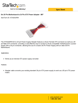
1.1 Introduction
Figure 1-1: IMBA-G410
The IMBA-G410 is an ATX motherboard with an 800/1066/1333 MHz front side bus. The
LGA775 socket accepts Intel® Core™2 Duo/Quad processors and the motherboard
supports two DDR3 DIMMs up to 4.0 GB each (8.0 GB total). The IMBA-G410 includes
VGA output with up to QXGA resolution. Multiple expansion cards may be added,
including PCIe x16, PCIe x4 and PCI interface. Other features include four SATA 3Gb/s,
dual PCIe GbE, digital I/O, five RS-232 serial ports, one RS-232/422/485 serial ports, one
parallel port, audio jacks and eight USB ports.
1.2 Benefits
Some of the IMBA-G410 motherboard benefits include:
Powerful graphics
Staying connected with both wired LAN connections
Speedy running of multiple programs and applications
Multiple expansion capabilities

2011/8/172011/8/17
IMBA-G410 ATX Motherboard
Page 3
1.3 Features
Some of the IMBA-G410 motherboard features are listed below:
ATX form factor
RoHS compliant
LGA775 CPU socket
Supports two DDR3 DIMMs
Supports dual display by VGA port and an optional PCIe x16 SDVO
expansion card
Two Gigabit Ethernet connectors
Four SATA connectors
Eight USB ports
Six serial ports
Supports PCI and PCIe x4 (PCIe x1 signal) expansion cards

48/17/2011158
Page 4
IMBA-G410 ATX Motherboard
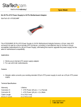
1.4 Connectors
The connectors on the IMBA-G410 are shown in the figure below.
Figure 1-2: Connectors

2011/8/172011/8/17
IMBA-G410 ATX Motherboard
Page 5
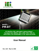
1.5 Dimensions
The main dimensions of the IMBA-G410 are shown in the diagram below.
Figure 1-3: Dimensions (mm)

68/17/2011158
Page 6
IMBA-G410 ATX Motherboard
1.6 Data Flow
556Figure 1-4 shows the data flow between the system chipset, the CPU and other
components installed on the motherboard.
Figure 1-4: Data Flow Diagram
/