Page is loading ...

Service Guide
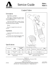
Cord Reel with RV Plug
7261
SER 7261
Revision (6-05)
670872
Copyright 2005 by Alemite, LLC
This document contains confidential information that is the property of Alemite, LLC
and is not to be copied, used, or disclosed to others without express written permission.
Alemite, LLC
167 Roweland Drive
Johnson City, TN 37601
www.alemite.com
1-800-548-1191-http://[email protected]

Alemite, LLC Revision (6-05)
2
SER 7261
IMPORTANT
READ THIS MANUAL CAREFULLY BEFORE INSTALLING,
OPERATING, OR SERVICING THIS EQUIPMENT
PERSONNEL SAFETY
Personal injury and/or equipment damage may
result if proper safety precautions are not observed.
• Ensure that only a qualified electrician installs/services this
equipment.
• Ensure that power supply voltage does not exceed maxi-
mum voltage rating of reel.
• Ensure that reel is properly installed before connecting to
power supply.
• Ensure that all electrical power is removed from reel be-
fore servicing.
• A high-tension spring assembly is contained within the
reel. Exercise extreme caution.
• Check for frayed and/or broken wires before each use.
Pull electrical cord from reel by grasping the electrical
cord itself, not the work device.
• If an electrical malfunction should occur, remove
power from reel immediately.
• Ensure that reel, electrical cord, and equipment being ser-
viced are properly grounded. Use an ohmmeter to check
ground continuity.
• If reel ceases to unwind or rewind, remove power
immediately. Do not pull or jerk on electrical cord!
• Treat and respect the reel as any other piece of machinery,
observing all common safety practices.
WARNING:
DIMENSIONAL DATA
Even low voltage can cause irreparable damage or
death! Exercise extreme caution while operating or
servicing this equipment.
Four 5/16" (7.9 mm) diameter mounting holes
Fig. 1
CORD APPARATUS
VOLTAGE
A/C
AMPS
RV Plug
120
35
Frequency 60HZ single phase
ELECTRICAL INFORMATION
1-800-548-1191-http://[email protected]

Alemite, LLC Revision (6-05)
3
SER 7261
INSTALLATION INSTRUCTIONS
1
2
3
MOUNTING (FIG. 2)
1. Unpack and inspect reel for damage. Turn by hand
to check for smooth operation. Check for complete-
ness.
2. Configure reel for top, side or bottom-wind (bottom-
wind for constant tension reels only) electrical cord
dispensing by removing bolts (1) securing guide
arm bracket (2). Determine new guide arm location
and remove corresponding bolts. Position guide
arm bracket to reel and replace bolts.
3. Position reel on floor, wall, or ceiling. Secure into
place, using four (customer supplied) screws or
bolts (3).
ELECTRICAL
WARNING:
Ensure that application does not exceed electrical
rating of reel.
Observe applicable NEC, OSHA, and local electrical
codes when installing this equipment.
1. Connect input cord to proper electric supply.
CAUTION:
Maximum installation height is 16 feet (4.9 m). Do
not exceed this distance.
Ensure that only a qualified electrician installs/ser-
vices this equipment.
ADJUSTMENTS
SPRING TENSION
If necessary, adjust spring tension on reel by adding or
removing wraps of electrical cord from spool, one wrap at a
time, until desired tension is obtained. Add wraps to increase
tension. Remove wraps to decrease tension.
WARNING:
When adding wraps of electrical cord, be careful not to
exceed the winding mechanism's spring capacity. Add
just enough wraps of cord to achieve the desired tension.
Damage to the winding mechanism will result if spring
is over-tightened.
Always be aware of spring tension on reel. Exercise
extreme caution.
TROUBLESHOOTING INSTRUCTIONS
Troubleshooting of the reel consists of isolating a problem to
a defective electrical cord/work device, brush holder/brushes,
or collector assembly. Refer any other discrepancies only to
an authorized service person or directly to Alemite.
WARNING:
The following procedure directs the technician to
take voltage measurements.
Remember, even low voltage is dangerous and can
cause personal injury or death. Exercise extreme
caution!
Ensure that only a qualified electrician installs/ser-
vices this equipment.
Fig. 2
Fig. 3
1
10
2
3
4
7
5
6
8
9
1-800-548-1191-http://[email protected]

Alemite, LLC Revision (6-05)
4
SER 7261
SERVICE INSTRUCTIONS
REPLACING THE INPUT ELECTRICAL
CABLE
WARNING:
Remove power from reel before performing any of
the following procedures.
WARNING:
Use extreme caution, reel under tension. Avoid
releasing latch mechanism.
Use only 10/3 cable.
See Fig. 3
Remove power from reel.
Remove access cover (8) from reel.
Remove three wire nuts (10) securing input electrical
cable wires to collector ring assembly wires. Ensure that
bare wires do not contact each other or the reel super-
structure.
Apply power to reel.
Using a voltmeter, check voltage between black wire
(hot) and white wire (neutral). If voltage reading is cor-
rect (120 vac), proceed to step 6. If voltage reading is in-
correct, replace input electrical cable (refer to SERVICE
INSTRUCTIONS).
Remover power from reel
Using an ohmmeter, check continuity of output electri-
cal cord. If cord checks good, replace reel. If cord is
faulty, replace cord (refer to SERVICE INSTRUC-
TIONS).
Replace access cover (8).
1.
2.
3.
4.
5.
6.
7.
8.
Remove access cover (8) from reel.
Remove three wire nuts (10) connecting input electrical
wires (2) to collector ring ass'y wires.
Unscrew elbow (1) from reel & pull out input cable
from main shaft & elbow.
Feed input wires (2) through elbow (1) and main shaft.
Screw elbow (1) into reel.
Connect input wires (2) and collector ring wires together
using wire nuts (10).
Assemble cover (8) to reel.
1.
2.
3.
4.
5.
6.
7.
WARNING:
Use only 10/3 cable.
REPLACING THE OUTPUT ELECTRICAL
CORD
Pull output electrical cable from reel until cable is fully
extended, then latch.
Remove access cover (8).
Remove two wire nuts (7) securing output electrical
cable wires (5) to collector assembly brush wires (6).
Remove output electrical cable ground wire from ground
lug (9).
Loosen U-clamp (3).
Remove output electrical cable.
Remove cable bumper (4).
Remove 6" of output electrical cable outer jacket.
Route cable through guide arm and U-clamp (3) then
through cut-out in spool.
Tighten U-clamp (3).
Using wire nuts (7), connect output electrical cable wires
(5) to collector assembly brush wires (6) as indicated in
illustration.
Connect ground wire of output electrical cable to ground
lug (9).
Using an ohmmeter, check for ground faults.
Replace access cover (8).
Release latch and wind output electrical cable onto reel.
Install cable bumper (4).
1.
2.
3.
4.
5.
6.
7.
8.
9.
10.
11.
12.
13.
14.
15.
16.
See Fig. 3
See Fig. 3
1-800-548-1191-http://[email protected]

Alemite, LLC Revision (6-05)
5
SER 7261
REPLACEMENT PARTS
Fig. 4
2
1
3
4
5
Item No. Description Part No.
1 Bumper Ass'y 393539-113
2 Cam, Latch 393539-114
3 Spring, Latch Plate 393539-110
4 Latch Bumper 393539-111
5 Latch Plate Ass'y 393539-112
1-800-548-1191-http://[email protected]
/