Page is loading ...

Service Guide
High Capacity Twin Hose Reel
7343
7344
Alemite, LLC
167 Roweland Drive, Johnson City, Tennessee 37601
www.alemite.com
Copyright
©
2005 by Alemite, LLC
This document contains confidential information that is the property of Alemite, LLC
and is not to be copied, used, or disclosed to others without express written permission.
SER 7343
Revision (11-08)
670911
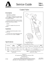
Description
High capacity hose reel models 7343 and 7344 are
designed to handle twin hose used for supply and return of
hydraulic fluid to power portable hydraulic powered tools.
These reels are suitable for outdoor applications.
Each model reel is spring-powered and self-retracting.
When the hose is extended, the reel can be latched on either
of two ratchet sections per revolution of the sheave. A pull
releases the latch from the ratchet and allows the hose to
retract onto the reel.
NOTE: The Hose Guide Arms can attach to the
Base Assembly in five (5) different positions.
Optional Mount
CAUTION
Install these reels at a height no greater than 16 feet
(4.9 m) from the floor to comply with the warranty.
These reels can also mount on a ceiling or to a wall.
Reel Package
Model
Hose Reel
(Bare)
Delivery Hose
Hose Stop
Max. Pressure
w/ Hose
Part # Description psi bar
8080-K 7343 340326-80
3/8 " ID One-Wire Braid
3/8 " NPTF (m) x 3/8 " NPTF (m)
339389-3
2000 138
8080-L 7344 340328-80
1/2 " ID One-Wire Braid
1/2 " NPTF (m) x 1/2 " NPTF (m)
339389-4
Delivery hose length is designated by the dash number. Example: 340326-80 is 80 feet long.
Table 1 Reel Packages
Figure 1 High-Capacity Twin Hose Reel
Model 7343 and 7344
Reel Model
Connecting
Hose Ports
Delivery
Hose Ports
Reel Max. Pressure
psi bar
7343 3/8 " NPTF (f) 3/8 " NPSM (f)
3000 207
7344 1/2 " NPTF (f) 1/2 " NPSM (f)
1-800-548-1191-http://[email protected]

SER 7343 High Capacity Twin Hose Reel
Revision (11-08) 2 Alemite, LLC
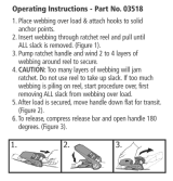
Figure 2 High Capacity Twin Hose Reel Model 7343 and 7344 - Exploded View
1-800-548-1191-http://[email protected]

High Capacity Twin Hose Reel SER 7343
Alemite, LLC 3 Revision (11-08)
Item
No.
Part No. Description and Model Qty Notes
Numeric Order
Part # (Item #)
1
131586 Bushing 7343 4
14534
(15)
2 340305 Swivel Assembly
All
2 See Figure 3
50876
(16)
3
Nut, Flange 3/8 " -16 11
4 in Kit, 1 in Kit
131586 (1)
4
Arm, Long 1 w/o Decal X171000-5 (35)
5
171007-33 Ring, Retaining 3 171007-33 (5)
6
339457 Housing, Bearing 2 Includes Two Halves 339197 (27)
7
339456 Bearing 2
339208
(9)
8
Base Assembly 1 339210 (29)
9
Washer, 0.445 " ID x 0.75" OD 8 339219 (14)
10
Bolt, Ribbed-Neck, 3/8 " -16 x 1-1/4 " 2 339219-4 (14)
11
Bolt, Ribbed-Neck, 3/8 " -16 x 3/4 " 2
339435
(8)
12
Screw, 5/16 " -18 x 3/4 " 20
339439
(28)
13
339467 Ratchet 1
339441
(30)
14
339219 U-Bolt 7343 2
339442
(18)
339219-4 U-Bolt 7344 2
339446
(23)
15
Washer, 5/16 "
All
4
339447
(4)
16
Nut, Wing, 1/4 " -20 4
339448
(32)
17 Nut, Flange 5/16 " -18 16
339451-2
(34)
18
Sheave Assembly (w/o Decal) 1
339451-3
(33)
19
339458 Shaft 1 339456 (7)
20
340302 Shaft and Flange Assembly 1 339457 (6)
21
339521 Key, Square 1 339458 (19)
22
339459-1 Union, 90 °, 3/8 " NPTF x 3/8 " NPSM 7343 2 339459-1 (22)
339459-2 Union, 90 °, 1/2 " NPTF x 1/2 " NPSM 7344 2 339459-2 (22)
23
Arm, Short
All
1
339460
(31)
24
340250 Gasket 1
339461
(12)
25
340251 Grommet 1
339462
(3)
26
339469-2 Spring Assembly, Power 1 Includes Gasket
339463
(11)
27
339197 Arbor, Spring 1 339467 (13)
28
Pawl and Shaft Assembly 1
339469-2 (26)
29
339210 Spring, Extension 1
339484
(10)
30
Post, Spring 1
339516-2
(36)
31
Screw, 1/2 " -13 x 3/4 " 1
339516-3
(37)
32 Plate, Hose Guide 1 339521 (21)
33 Roller Assembly, Short 2 340250 (24)
34 Roller Assembly, Long 2 340251 (25)
35 X171000-5 O-Ring, 1/4 " ID x 3/8 " OD 8 Pack of Ten 340302 (20)
36 Post and Shaft Assembly, Long 2 340305 (2)
37 Post and Shaft Assembly, Short 2
387370
(17)
Legend:
Part numbers left blank (or in italics) are not available separately
designates a repair kit item
Repair Kits
Part No. Kit Symbol Description
393723 Kit, Hose Guide
393724 Kit, Pawl and Shaft Assembly
1-800-548-1191-http://[email protected]

SER 7343 High Capacity Twin Hose Reel
Revision (11-08) 4 Alemite, LLC
WARNING
Release all pressure within the system prior to
performing any maintenance procedure.
Turn off the power supply.
Operate the hydraulic tool to relieve the remaining pres-
sure within the system.
Maintenance
Read each step of the instructions carefully. Make sure a
proper understanding is achieved before proceeding.
Delivery Hose Replacement
1. Extend the delivery hose completely from the reel.
WARNING
Precautions must be taken to ensure the
Sheave Assembly remains engaged with the Power
Spring’s ratchet. To prevent movement either:
• instruct an assistant to grip the Sheave Assembly
securely with non-slip gloved hands or
• install a clamp on the Sheave Assembly
Personal injury can occur.
2. Remove the hydraulic tool and hose stop.
3. Disconnect the delivery hose from 90 ° Unions (22).
4. Remove Wing Nuts (16) and Washers (15) that secure
U-Bolts (14) to the hose.
• Remove the hose.
5. Feed the end of the new delivery hose through the Hose
Guide Assembly.
6. Connect the delivery hose to the 90 ° Unions.
HINT: Orient the hose to allow its natural curve
to match the Sheave. This reduces torque load on
Power Spring Assembly (26).
7. Secure the delivery hose to the Sheave Assembly with
U-Bolts (14), Washers (15) and Wing Nuts (16).
8. Install the hydraulic tool (with thread sealant) and hose stop
to the delivery hose.
IMPORTANT: Allow some slack on the hose
between the U-Bolt and the 90 ° Unions.
9. Pressurize the system and check for leaks.
10. Carefully release the Sheave Assembly and retract the hose
onto the reel.
11. Check the Spring Tension.
• Please refer to the section entitled Installation for details.
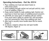
Item # Part No. Description Notes Qty
2a Ring, Retaining 1
2b Ring, Back-Up 2
2c X171009-17 O-Ring, 13/16 " ID x 1 " OD 2
2d Body, Swivel 1
2e 340304 Stem, Swivel 1
2f X171009-18 O-Ring, 7/8 " ID x 1-1/16 " OD 1
Legend:
Part numbers left blank are not available separately
Part number with an X prefix indicates a quantity of ten (10)
designates the parts available in Repair Kit 393781
Figure 3 Swivel Assembly 340305 - Exploded View
Disassembly
WARNING
Release the tension on the power spring. Per-
sonal injury can occur.
Power Spring, Arbor, and Sheave Removal
1. Remove the Arm and Hose Guide assembly from Base
Assembly (8).
2. Unscrew Swivel Stem (2e) from Shaft and Flange Assembly
(20).
3. Disassemble the Swivel Assembly as required.
• See Figure 3.
4. Remove Screws (12) that secure Power Spring Assembly (26)
to the Base Assembly.
• Remove the Power Spring Assembly.
5. Remove Retaining Ring (5) that secures Spring Arbor (27) to
the Shaft and Flange Assembly.
• Remove the Spring Arbor and Key (21).
6. Remove Nuts (3) that secure the Bearing and Housing
assembly to the Base Assembly.
1-800-548-1191-http://[email protected]

High Capacity Twin Hose Reel SER 7343
Alemite, LLC 5 Revision (11-08)
7. Remove Bearing Housing (6) and Bearing (7) from the Shaft
and Flange Assembly.
8. Remove the Sheave Assembly from the Base Assembly.
9. Refer to Figures 2 through 4 for further disassembly.
WARNING
Do not attempt to disassemble Power Spring
Assembly (26). Personal injury can occur.
Assemble and Replace
NOTE: Prior to assembly, certain components
require lubrication. Refer to Table 2 for details.
Refer to Figures 2 through 4 for any assembly
not covered below.
Sheave and Arbor Assembly
1. Position the Sheave assembly [w/ Bearing (7) and Bearing
Housing (6)] into Base Assembly (8).
2. Install Shaft (19) through Ratchet (13) and Bearing (7).
3. Install Nuts (3) that secure the Bearing Housing assembly to
the Base Assembly.
• Tighten the Nuts securely.
4. Install Retaining Ring (5) that secures Shaft (19) to the
Bearing.
5. Install Key (21) into the slot of Shaft and Flange Assembly
(20).
6. Slide Spring Arbor (27) [flat side first] onto the Shaft and
Flange Assembly and Key.
7. Install Retaining Ring (5) that secures the Spring Arbor to
the Shaft and Flange Assembly.
Power Spring Assembly
8. Remove Grommet (25) from the Power Spring Assembly.
9. Install Power Spring Assembly (26) onto the Spring Arbor.
• Make sure the hook on the Power Spring’s inner coil
properly engages the recess in the Spring Arbor.
Hint: Lift and center the coil within the case dur-
ing installation.
• Use care not to damage the gasket.
10. Align the Screw holes in the Power Spring Assembly with
the Base Assembly.
11. Secure the Power Spring Assembly to the Base Assembly
with Screws (12).
• Tighten the Screws securely in an alternate pattern.
12. Install the Grommet into the case of the Power Spring
Assembly.
13. Screw the Swivel Assembly into the Shaft and Flange
Assembly.
• Tighten Swivel Stem (2e) securely.
NOTE: The Hose Guide Arms can attach to the
Base Assembly in five (5) different positions.
Select the required relationship of the Guide to
the mounting plate of the Base Assembly.
14. Install the Arm and Hose Guide assembly onto the Base
Assembly.
Bench Test
While facing the ratchet side of the reel, turn the reel in a
counterclockwise direction and allow the ratchet to latch onto
Pawl and Shaft Assembly (28).
If the reel does not tension or latch properly, refer to the
Troubleshooting Chart.
Components Lubricated with NLGI 2 EP Lithium Grease
Item No. Description Notes
2b Rings, Back-Up
2c O-Rings, 5/8 " ID x 13/16 " OD
2e Land surfaces of Swivel Stem See Figure 3
13 Teeth of Ratchet
28 Bearing surface of Pawl Shaft
28 Wave Washer
29 Hooks of Pawl Spring
Components Lubricated in Oil
2f O-Ring, 7/8 " ID x 1-1/16 " OD
35 O-Ring, 1/4 " ID x 3/8 " OD
Table 2 Lubricated Components
1-800-548-1191-http://[email protected]

SER 7343 High Capacity Twin Hose Reel
Revision (11-08) 6 Alemite, LLC
Installation
WARNING
Do not exceed the lowest pressure rating of
any component in the system.
Ensure all components are in operable condition.
Replace any suspect parts prior to operation.
Hold the delivery hose securely until the reel is securely
latched or fully retracted. Uncontrolled retraction can
result in personal injury.
1. Connect the delivery hose securely to 90 ° Unions (22).
HINT: Orient the hose to allow its natural curve
to match the Sheave. This reduces torque load on
Power Spring Assembly (26).
2. Secure the delivery hose to the Sheave Assembly with
U-Bolts (14), Washers (15) and Wing Nuts (16).
IMPORTANT: Allow some slack on the hose
between the U-Bolts and the 90 ° Unions.
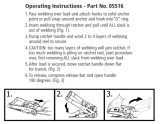
Figure 4 High Capacity Twin Hose Reel Model 7343 and 7344 - Section View
3. Rotate the Sheave Assembly to wrap the hose completely
onto the reel.
• The clicking sound is the power spring bypassing the cam
on Spring Arbor (27).
Setting Spring Tension
To adjust tension on the power spring:
4. Rotate the Sheave Assembly in the opposite direction 5
turns.
• This sets the power spring tension.
IMPORTANT: When the hose is fully extended
from the reel, the power spring should be a mini-
mum of 1/2 turn from a fully wound condition.
5. Allow the reel to latch.
6. Feed the end of the delivery hose through the Hose Guide
Assembly.
7. Install and secure the hose stop.
8. Mount the reel assembly with the appropriate hardware as
required.
9. Adjust the hose stop to the desired position.
1-800-548-1191-http://[email protected]

High Capacity Twin Hose Reel SER 7343
Alemite, LLC 7 Revision (11-08)
CAUTION
Never connect rigid piping to the Swivel assemblies.
Damage to components can occur.
10. Attach the connecting hoses to the distribution system (with
thread sealant) and to the inlets of the reel as required.
IMPORTANT: Anchor the connecting hoses to a
suitable surface to prevent the hose from flexing
at the Swivel Assembly. The anchor should be in-
line with the inlet of the Swivel to minimize side
loading.
11. Attach the hydraulic tool to the delivery hose (with thread
sealant).
12. Pressurize the system and check for leaks.
Checking Spring Tension
Check to ensure the tension on the power spring is sufficient
to properly hold the hose stop against the Hose Guide.
Should the power spring tension require adjustment:
13. Release all pressure within the system.
WARNING
Turn off the power source.
Operate the hydraulic tool to relieve the remaining pres-
sure within the system.
14. Remove the hydraulic tool and the hose stop from the
delivery hose.
15. Unlatch the reel and allow the free end of the delivery hose
to pass through the Hose Guide.
CAUTION
Do not overwind the power spring. Too much tension
reduces the life of the spring.
16. Rotate the Sheave Assembly in the required direction.
17. Pass the free end of the hose through the Hose Guide.
18. Install the hydraulic tool and the hose stop.
19. Pressurize the system and check for leaks.
20. Check to ensure the tension on the power spring is sufficient
to properly hold the hose stop against the Hose Guide.
21. Repeat steps 13 - 20 until the proper tension is achieved.
Latch Lockout
Reel Over-Run
IMPORTANT: Do not extend the hose from the
reel too rapidly. Too much velocity can cause the
reel to over-run and latch.
Should latch lockout occur, pulling on the hose will not
release the latch mechanism.
With the reel latch in this condition it will be necessary to
have an assistant maintain tension on the hose while the latching
mechanism is manually released.
WARNING
The reel is under maximum spring tension.
Personal injury can occur.
1. Instruct the assistant to grip the hose securely with both
hands to prevent uncontrolled retraction.
2. Grip Sheave Assembly (18) securely with gloved hands.
3. Turn the Sheave Assembly in the direction just enough that
allows Pawl and Shaft Assembly (28) to be free of tension
from the ratchet on Power Spring Assembly (26).
• This direction further increases tension on the power
spring.
4. While maintaining the position of the Sheave assembly with
one hand, move the Pawl away from the ratchet.
• Use a screwdriver or other suitable tool.
5. Instruct the assistant to allow the hose to retract slowly onto
the Sheave Assembly.
1-800-548-1191-http://[email protected]

SER 7343 High Capacity Twin Hose Reel
Revision (11-08) 8 Alemite, LLC
Troubleshooting Chart
Indications Possible Problems Solution
Reel does not latch Pawl Spring (29) broken or not attached to Pawl and
Shaft Assembly (28)
Replace or secure Pawl Spring (29)
Reel does not retract Power spring broken* Replace Power Spring Assembly (26)
Reel retracts partially 1. Improper power spring tension
2. Hose length greater than recommendation
1. Adjust tension
2. See Table 1.
Reel does not unlatch
after maximum length
of hose is removed
1. Power spring wound solid
2. Hose removed from the reel too quickly
(Reel Over-Run)
1. Decrease power spring pre-wind
2. Remove hose slowly when close to being fully
extended
Material leakage at
Swivel Assembly (2)
1. Connection not sufficiently tight and / or thread
sealant missing at Bushing (1)
2. Worn or damaged O-Rings (2c)
3. Worn or damaged O-Ring (2f)
4. Worn or damaged Swivel Stem (2e)
1. Apply sealant to male threads of
Bushing (1) and tighten connections
2. Replace O-Rings (2c)
3. Replace O-Ring (2f) or use Repair Kit 393781
4. Replace Swivel Stem (2e)
Material leakage from
delivery hose
connections
1. Delivery hose connection not sufficiently tight
2. Thread sealant missing at Unions (22) or Bushings
(1) and / or Unions and / or Bushings not
sufficiently tight into Shaft (19) or Shaft and
Flange Assembly (20)
1. Tighten connection
2. Apply thread sealant to Unions (22) or Bushings
(1) and tighten into Shaft (19) or Shaft and
Flange Assembly (20)
* The possible causes for broken components are listed in italics
Changes Since Last Printing
339389-3 for 8080-K
339389-4 for 8080-L
1-800-548-1191-http://[email protected]
/