Page is loading ...

T1DMK34
4 Door Kit with Fused Outputs
Fully assembled kit includes:
- Trove1 enclosure with TDM1 Altronix/DMP backplane
- One (1) AL600ULXB - Power Supply/Charger
- One (1) VR6 - Voltage Regulator
- One (1) PDS8 - Dual Input Fused Power Distribution Module
T2DMK78
8 Door Kit with Fused Outputs
Fully assembled kit includes:
- Trove2 enclosure with TDM2 Altronix/DMP backplane
- One (1) AL1024ULXB2 - Power Supply/Charger
- One (1) ACM8 - Fused Access Power Controller
- One (1) VR6 - Voltage Regulator
- One (1) PDS8 - Dual Input Fused Power Distribution Module
T1DMK34D
4 Door Kit with PTC Outputs
Fully assembled kit includes:
- Trove1 enclosure with TDM1 Altronix/DMP backplane
- One (1) AL600ULXB - Power Supply/Charger
- One (1) VR6 - Voltage Regulator
- One (1) PDS8CB - Dual Input PTC Power Distribution Module
T2DMK78D
8 Door Kit with PTC Outputs
Fully assembled kit includes:
- Trove2 enclosure with TDM2 Altronix/DMP backplane
- One (1) AL1024ULXB2 - Power Supply/Charger
- One (1) ACM8CB - PTC Access Power Controller
- One (1) VR6 - Voltage Regulator
- One (1) PDS8CB - Dual Input PTC Power Distribution Module
Access & Power Integration
Altronix/DMP 734/734N Wiegand Kits
Models Include:
Rev. TDMKL_122121
Installing Company: _________________________ Service Rep. Name: __________________________________________
Address: _________________________________________________________ Phone #: _________________________
All registered trademarks are property of their respective owners. More than just power.™
Installation Guide
All components of these Trove kits are UL Listed sub-assemblies.
Please refer to the included corresponding Sub-Assembly Installation Guides for further information.

- 2 - Trove DMP ULXB Kits Installation Guide
Overview:
Altronix T1DMK34(D) and T2DMK78(D) Trove DMP kits are pre-assembled and consist of Trove enclosures/backplanes with factory installed
Altronix power supply/chargers and sub-assemblies.
T1DMK34(D) accommodates up to four (4) DMP 734/734N Wiegand modules for up to four (4) doors in a single enclosure.
T2DMK78(D) accommodates up to eight (8) DMP 734/734N Wiegand modules for up to eight (8) doors in a single enclosure.
Configuration Chart:
Altronix
Model
Number
115VAC
60Hz
Input
Current
(A)
Power
Supply
Board
Input
Fuse
Rating
Power
Supply
Board
Battery
Fuse
Rating
Maximum Supply
Current for Main and Aux.
Outputs on Power Supply
board and ACM8(CB)
Access Power Controllers’
outputs
Nominal
DC
Output
Voltage
Range
(VDC)
Fail-Safe/Fail-Secure
or Dry Form “C”
Outputs
Additional Fused
Outputs
ACM8(CB) Board
Input Fuse Rating
ACM8 Board
Output Fuse Rating
ACM8CB Board
Output PTC Rating
PDS8 Board
Input Fuse Rating
PDS8 Board
Output Fuse Rating
PDS8CB Board
Input PTC Rating
PDS8CB Board
Output PTC Rating
T1DMK34
3.5 5A/
250V N/A 24VDC @ 5.7A
20.17-
26.4
–
8
–––
10A/
32V
3A/
32V – –
T1DMK34D – 9A 2A
T2DMK78
4.2 5A/
250V
15A/
32V 24VDC @ 9.4A 810A/
250V
2.5A/
250V –10A/
32V
3A/
32V – –
T2DMK78D – 2.5A – – 9A 2A
Installation Instructions:
Wiring methods shall be in accordance with the National Electrical Code/NFPA 70/ANSI, and with all local codes and authorities having jurisdiction.
Product is intended for indoor use only.
1. Remove backplane from enclosure. Do not discard hardware.
2. Mark and predrill holes in the wall to line up with the top two/three keyholes in the enclosure. Install two/three upper fasteners and screws
in the wall with the screw heads protruding. Place the enclosure’s upper keyholes over the two/three upper screws; level and secure.
Mark the position of the lower three holes. Remove the enclosure. Drill the lower holes and install the three fasteners. Place the enclosure’s
upper keyholes over the two/three upper screws. Install the three lower screws and make sure to tighten all screws.
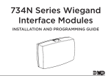
3. Mount included UL Listed tamper switch (Altronix Model TS112 or equivalent) in desired
location, opposite hinge. Slide the tamper switch bracket onto the edge of the enclosure
approximately 2” from the right side (Fig. 1, pg. 2). Connect tamper switch wiring to the
Access Control Panel input or the appropriate UL Listed reporting device.
To activate alarm signal open the door of the enclosure.
4. Mount DMP 734/734N Wiegand modules to backplane, refer to pages 3, 4.
5. Refer to the ULXB Power Supply/Charger Installation Guide for AL600ULXB,
AL1024ULXB2 and corresponding Sub-Assembly Installation Guides for ACM8(CB),
PDS8(CB) and VR6 for further installation instructions.
Hardware:
Nylon Spacer | 5/16” Pan Head Screw | Lock Nut
Fig. 1
Tamper Switch
(included)
To Access Control Panel or
UL Listed Reporting Device
Edge of
Enclosure
Enclosure

Trove DMP ULXB Kits Installation Guide - 3 -
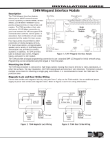
T1DMK34(D): Configuration of DMP 734/734N Wiegand Modules:
1. Fasten spacers (provided) to pems that match the hole pattern for DMP Wiegand Modules (Fig. 2, pg. 3).
2. Mount DMP 734/734N modules into the correct positions (Fig. 2, pg. 3):
a. Remove DMP 734/734N board from the plastic housing. Use the base part of the housing to mount onto TDM1 (Fig. 2a, 2b, pg. 3).
b. Secure the base of DMP 734/734N to the spacers using provided 5/16” pan head screws.
c. Make all necessary connections before reassembling DMP 734/734N Wiegland modules.
3. Fasten TDM1 backplane to Trove1 enclosure utilizing hardware (provided).
+ INP1 --
DM1 +OFF
IN1
IN2DM1 +
DM2 +
DM2 +
Common (--- )
Common (--- )
+ INP2 --
Common Power Outputs (NEG)
N
P
OUT1 OUT2 OUT3 OUT4 OUT5 OUT6 OUT7 OUT8
1 2 3 4 5 6 7 8
Altronix
PDS8(CB)
Altronix VR6 is mounted under PDS8(CB)
BAT FAIL NC C NO NC C NO AC FAIL
AC DC BAT
+BAT- + DC -
L G N
OFF - 24V
ON - 12V
ON
Altronix
AL600ULXB
DMP 734 or 734N
Wiegand
DMP 734 or 734N
Wiegand
DMP 734 or 734N
Wiegand
DMP 734 or 734N
Wiegand
Spacer
DMP 734 plastic housing
Backplane
Pan Head
Screw
Pem Mounting
Spacer
Placement
Fig. 2bFig. 2a
Fig. 2 - T1DMK34(D) Configuration

- 4 - Trove DMP ULXB Kits Installation Guide
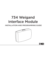
T2DMK78(D): Configuration of DMP 734/734N Wiegand Modules:
1. Fasten spacers (provided) to pems that match the hole pattern for DMP 734/734N Wiegand Modules (Fig. 3, pg. 4).
2. Mount DMP 734/734N modules into the correct positions (Fig. 3, pg. 4):
a. Remove DMP 734/734N board from the plastic housing. Use the base part of the housing to mount onto TDM2 (Fig. 3a, 3b, pg. 4).
b. Secure the base of DMP 734/734N to the spacers using provided 5/16” pan head screws.
c. Make all necessary connections before reassembling DMP 734/734N Wiegland modules.
3. Fasten TDM2 backplane to Trove2 enclosure utilizing hardware (provided).
OUTPUT 1 OUTPUT 2 OUTPUT 3 OUTPUT 4 OUTPUT 5 OUTPUT 6 OUTPUT 7 OUTPUT 8
NC C NO COM NC C NO COM NC C NO COM NC C NO COM NC C NO COM NC C NO COM NC C NO COM NC C NO COM
IN GND IN GND IN GND IN GNDIN GND IN GND IN GND IN GND
1 2 3 4 5 6 7 8
INPUT
TRIGGER
10A 250V
+INP- T + RET-
NO C NC
FACP INTERFACE
Power Control
- + - +
MAIN
TRG
FACP
1 2 3 4
1 2 3 4
ON
ON
1 2 3 4
1 2 3 4
ON
ON
Altronix ACM8(CB)
+ INP1 --
PWR1 +
PWR1 +
OFF
IN1
IN2
PWR2 +PWR2 +
COM ---
COM ---
+ INP2 --
Common Power Outputs (NEG)
N
P
OUT1 OUT2 OUT3 OUT4 OUT5 OUT6 OUT7 OUT8
1 2 3 4 5 6 7 8
Altronix PDS8(CB)
Altronix VR6 is mounted under PDS8(CB)
DMP 734
or 734N
Wiegand
DMP 734
or 734N
Wiegand
DMP 734
or 734N
Wiegand
DMP 734
or 734N
Wiegand
DMP 734
or 734N
Wiegand
DMP 734
or 734N
Wiegand
DMP 734
or 734N
Wiegand
DMP 734
or 734N
Wiegand
L
G
N
BAT FAIL
AC FAIL
NC
C
NO
NC
C
NO
AC
DC
- BAT + + DC -
AC DELAY
Altronix
AL1024ULXB2
Spacer
DMP 734 plastic housing
Backplane
Pan Head
Screw
Pem Mounting
Spacer
Placement
Fig. 3bFig. 3a
Fig. 3 - T2DMK78(D): Configuration

Trove DMP ULXB Kits Installation Guide - 5 -
Notes:

- 6 - Trove DMP ULXB Kits Installation Guide
Notes:

Trove DMP ULXB Kits Installation Guide - 7 -
T1DMK34 Enclosure Dimensions (H x W x D approximate):
18” x 14.5” x 4.625” (457mm x 368mm x 118mm)
4.5” (114.3mm) 4.5” (114.3mm) 2.75”
(69.9mm)
1.115” (28.3mm)
1.36” (34.5mm)
1.25” (31.8mm) 1.25” (31.8mm)
1.5” (38.1mm)
8.5” (215.9mm)6.5” (165.1mm)
1.5” (38.1mm)
8.5” (215.9mm)6.5” (165.1mm)
4.5” (114.3mm)
13.0” (330.2mm)
0.6” (15.2mm)
14.5” (321.3mm)
1.45” (36.8mm)
7.25” (184.2mm)
1.95” (49.5mm)
1.1” (27.9mm)
0.6” (15.2mm)
0.57” (14.5mm)
18.0” (457.2mm)
1.25” (31.8mm)

- 8 - Trove DMP ULXB Kits Installation Guide
T2DMK78 Enclosure Dimensions (H x W x D):
27.25” x 21.75” x 6.5” (692.2mm x 552.5mm x 165.1mm)
6.75” (171.5mm)8.25” (209.5mm)
8.00” (203.2mm)
2.00” (50.8mm)
2.00” (50.8mm)
1.25” (31.8mm)
1.25” (31.8mm)
5.25” (133.4mm) 5.25” (133.4mm)7.00” (177.8mm)
1.25” (31.8mm)
6.25” (158.8mm) 19.80” (502.9mm)
1.00” (25.4mm)
27” (685.8mm)
1.5”
(38.1mm)
2.00” (50.8mm) 2.00” (50.8mm)
3.5”(88.9mm) 3.5”(88.9mm)
21.50” (546.1mm)
5.25” (133.35mm) 5.25” (133.35mm)
6.25” (158.8mm)
1.25”
(31.8mm)
0.85” (21.6mm)
0.5625” (14.3mm)
2.415” (61.3mm)
0.685” (17.4mm)
1.77”
(45mm)
0.885” (22.5mm)
1.125” (28.3mm)
Knockouts
2.00” (50.8mm) 2.00” (50.8mm)
Altronix is not responsible for any typographical errors.
––––––––––––––––––––––––––––––––––––––––––––––––––––––––––––––––––––––––––––––––––––––––––––––––––––––––––––––––––––––––––––––––––––––––––––––––––––––––
140 58th Street, Brooklyn, New York 11220 USA | phone: 718-567-8181 | fax: 718-567-9056
web site: www.altronix.com | e-mail: [email protected] | Lifetime Warranty
IITrove DMP ULXB Kits L21U MEMBER
/