Page is loading ...

Rev. TDMP103017
Trove1DM1
- Trove1 enclosure with Altronix/DMP backplane (TDM1)
TDM1
- Altronix/DMP backplane only
Trove2DM2
- Trove2 enclosure with Altronix/DMP backplane (TDM2)
TDM2
- Altronix/DMP backplane only
Installation Guide
All registered trademarks are property of their respective owners. More than just power.™
Installing Company: _____________________ Service Rep. Name: __________________________________________
Address: ________________________________________________________ Phone #: _________________________
Access & Power Integration

- 2 - Trove1DM1 / TDM1 / Trove2DM2 / TDM2
Overview:
Trove1DM1 and Trove2DM2 accommodate DMP 734 and 734N Wiegand Modules with or without Altronix power supplies
and accessories for access control systems.
Specifications:
• 16 Gauge grey backplane and enclosure with ample knockouts for convenient access.
Installation Instructions for Trove1 and Trove2:
1. Remove backplane from enclosure prior to mounting (do not discard hardware).
2. Trove1DM1 (Pg. 7):
Mark and predrill holes on the wall to line up with the top two keyholes in the enclosure. Install two upper fasteners and
screws in the wall with the screw heads protruding. Place the enclosure’s upper keyholes over the two upper screws;
level and secure. Mark the position of the lower two holes. Remove the enclosure. Drill the lower holes and install the
two fasteners. Place the enclosure’s upper keyholes over the two upper screws.
Install the two lower screws and make sure to tighten all screws.
Trove2DM2 (Pg. 8):
Mark and predrill holes on the wall to line up with the top three keyholes in the enclosure. Install three upper fasteners
and screws in the wall with the screw heads protruding. Place the enclosure’s upper keyholes over the three upper screws;
level and secure. Mark the position of the lower three holes. Remove the enclosure. Drill the lower holes and install the
three fasteners. Place the enclosure’s upper keyholes over the three upper screws.
Install the three lower screws and make sure to tighten all screws.
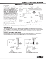
3. Mount included UL Listed tamper switch (Honeywell Model 112 or equivalent) in desired location, opposite hinge.
Slide the tamper switch bracket onto the edge of the enclosure approximately 2” from the right side (Fig. 1, pg. 1).
Connect tamper switch wiring to the Access Control Panel input or the appropriate UL Listed reporting device.
To activate alarm signal open the door of the enclosure.
4. Mount Altronix/DMP modules to TDM1 or TDM2 backplane, refer to pages 3, 4.
Edge of
Enclosure
to Access Control Panel
or U.L. Listed
Reporting Device
Enclosure
Honeywell
model # 112
Tamper Switch
or equivalent
(provided)
Fig. 1
Trove1DM1
Trove1 enclosure with TDM1 Altronix/DMP backplane
• Includes: tamper switch, cam lock, lock nuts,
and mounting hardware.
Enclosure Dimensions (H x W x D):
18” x 14.5” x 4.625” (457mm x 368mm x 118mm).
TDM1
Altronix/DMP backplane only
• Includes mounting hardware.
Dimensions (H x W x D):
16.625” x 12.5” x 0.3125” (422.3mm x 317.5mm x 7.9mm).
TDM1 accommodates a combination of the following:
Altronix Modules:
• One (1) AL400ULXB2, AL600ULXB, AL1012ULXB,
AL1024ULXB2,
eFlow4NB, eFlow6NB, eFlow102NB or eFlow104NB.
• One (1) ACM4(CB), MOM5, PD4UL(CB), PD8UL(CB),
PDS8(CB), VR6.
DMP Modules:
• Up to eight (8) DMP 734 and/or 734N modules.
Trove2DM2
Trove2 enclosure with TDM2 Altronix/DMP backplane
• Includes: tamper switch, cam lock, lock nuts,
and mounting hardware.
Enclosure Dimensions (H x W x D):
27.25” x 21.75” x 6.5” (692.2mm x 552.5mm x 165.1mm).
TDM2
Altronix/DMP backplane only
• Includes mounting hardware.
Dimensions (H x W x D):
25.375” x 19.375” x 0.325” (644.5mm x 482.6mm x 8.3mm)
TDM2 accommodates a combination of the following:
Altronix Modules:
• Two (2) AL400ULXB2, AL600ULXB, AL1012ULXB,
AL1024ULXB2,
eFlow4NB, eFlow6NB, eFlow102NB or eFlow104NB.
• Two (2) ACM8(CB), MOM5, PD4UL(CB),
PD8UL(CB), PDS8(CB), VR6.
DMP Modules:
• Up to sixteen (16) DMP 734 and/or 734N modules.

Trove1DM1 / TDM1 / Trove2DM2 / TDM2 - 3 -
Standoff
Altronix
Sub-Assembly or
DMP 734 plastic housing
Backplane
Pan Head
Screw
Pem
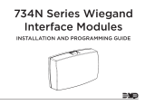
TDM1: Configuration of Altronix Power Supply
and/or Sub-Assembly Boards and DMP 734 and/or 734N Wiegand Modules
1. Fasten standoffs (provided) to pems that match the hole pattern for Altronix Power Supply/Chargers or Altronix
Sub-Assembly boards (Fig. 2, pg. 3). Fasten metal standoffs in the correct locations to provide proper grounding,
see below (Fig. 2, pg. 3).
2. Mount boards to standoffs utilizing 5/16” pan head screws (provided) (Fig. 2, 2a, pg. 3).
3. Mount DMP 734 and/or 734N modules into the correct positions (Fig. 2, pg. 3):
a. fasten standoffs to appropriate pems on the backplane (Fig. 2, 2b, pg. 3).
b. remove DMP 734 board from the plastic housing.
Use the base part of the housing to mount onto TDM1 (Fig. 2b, pg. 3).
c. secure the base of DMP 734 to the standoffs using provided 5/16” pan head screws.
d. make all necessary connections before reassembling DMP 734 Wiegland.
4. Fasten TDM1 backplane to Trove1 enclosure utilizing pan head screws (provided).
Altronix
Power
Supply
Metal
Standoff
Placement
Altronix
Sub-
Assembly
734
Interface
Module
734
Interface
Module
734
Interface
Module
734
Interface
Module
734
Interface
Module
734
Interface
Module
734
Interface
Module
734
Interface
Module
734
Interface
Module
734
Interface
Module
734
Interface
Module
734
Interface
Module
Mounting
Standoff
Placement
Fig. 2 - Trove1DM1/TDM1 Configurations
Fig. 2b
Fig. 2a

- 4 - Trove1DM1 / TDM1 / Trove2DM2 / TDM2
Altronix
Power Supply
Altronix
Power Supply
Altronix
Power Supply
or
Sub-Assembly
Altronix
Power Supply
or
Sub-Assembly
RED YELGRN
NO C NC
Piezo
+ -
KYPD OUTKYPD IN
PROG
RED
RED
J2 J4 J5
J1
J3
S1
ON
RELAY
ON
WEIGAND
READ LED
DATA
XMT LED
734
Interface
Module
RED
Door Relay
LEV
K1
PC-0085 P3
Address Switch
U1
RED
WHTGRNBLK LC RA AS Z1 GNDZ2Z3 GND Z4+Z4-
1
2
34
56
78
91011121314
RED YELGRN
NO C NC
Piezo
+ -
KYPD OUTKYPD IN
PROG
RED
RED
J2 J4 J5
J1
J3
S1
ON
RELAY
ON
WEIGAND
READ LED
DATA
XMT LED
734
Interface
Module
RED
Door Relay
LEV
K1
PC-0085 P3
Address Switch
U1
RED
WHTGRN BLK LC RA AS Z1 GNDZ2Z3 GND Z4+Z4-
1
2
34
56
78
91011121314
RED YELGRN
NO C NC
Piezo
+ -
KYPD OUTKYPD IN
PROG
RED
RED
J2 J4 J5
J1
J3
S1
ON
RELAY
ON
WEIGAND
READ LED
DATA
XMT LED
734
Interface
Module
RED
Door Relay
LEV
K1
PC-0085 P3
Address Switch
U1
RED
WHTGRN BLK LC RA AS Z1 GNDZ2Z3GND Z4+Z4-
1
2
34
56
78
91011121314
RED YELGRN
NO C NC
Piezo
+ -
KYPD OUTKYPD IN
PROG
RED
RED
J2 J4 J5
J1
J3
S1
ON
RELAY
ON
WEIGAND
READ LED
DATA
XMT LED
734
Interface
Module
RED
Door Relay
LEV
K1
PC-0085 P3
Address Switch
U1
RED
WHTGRN BLK LC RA AS Z1 GNDZ2Z3GND Z4+Z4-
1
2
34
56
78
91011121314
RED YEL GRN
NO C NC
Piezo
+ -
KYPD OUTKYPD IN
PROG
RED
RED
J2 J4 J5
J1
J3
S1
ON
RELAY
ON
WEIGAND
READ LED
DATA
XMT LED
734
Interface
Module
RED
Door Relay
LEV
K1
PC-0085 P3
Address Switch
U1
RED
WHTGRN BLK LC RA AS Z1 GNDZ2Z3GND Z4+Z4-
1
2
34
56
78
91011121314
RED YEL GRN
NO C NC
Piezo
+ -
KYPD OUTKYPD IN
PROG
RED
RED
J2 J4 J5
J1
J3
S1
ON
RELAY
ON
WEIGAND
READ LED
DATA
XMT LED
734
Interface
Module
RED
Door Relay
LEV
K1
PC-0085 P3
Address Switch
U1
RED
WHTGRN BLK LC RA AS Z1 GNDZ2Z3GND Z4+Z4-
1
2
34
56
78
91011121314
RED YEL GRN
NO C NC
Piezo
+ -
KYPD OUTKYPD IN
PROG
RED
RED
J2 J4 J5
J1
J3
S1
ON
RELAY
ON
WEIGAND
READ LED
DATA
XMT LED
734
Interface
Module
RED
Door Relay
LEV
K1
PC-0085 P3
Address Switch
U1
RED
WHTGRN BLK LC RA AS Z1 GNDZ2Z3GND Z4+Z4-
1
2
34
56
78
91011121314
RED YEL GRN
NO C NC
Piezo
+ -
KYPD OUTKYPD IN
PROG
RED
RED
J2 J4 J5
J1
J3
S1
ON
RELAY
ON
WEIGAND
READ LED
DATA
XMT LED
734
Interface
Module
RED
Door Relay
LEV
K1
PC-0085 P3
Address Switch
U1
RED
WHTGRN BLK LC RA AS Z1 GNDZ2Z3GND Z4+Z4-
1
2
34
56
78
91011121314
RED YELGRN
NO C NC
Piezo
+ -
KYPD OUTKYPD IN
PROG
RED
RED
J2 J4 J5
J1
J3
S1
ON
RELAY
ON
WEIGAND
READ LED
DATA
XMT LED
734
Interface
Module
RED
Door Relay
LEV
K1
PC-0085 P3
Address Switch
U1
RED
WHTGRN BLK LC RA AS Z1 GNDZ2Z3 GND Z4+Z4-
1
2
34
56
78
91011121314
RED YELGRN
NO C NC
Piezo
+ -
KYPD OUTKYPD IN
PROG
RED
RED
J2 J4 J5
J1
J3
S1
ON
RELAY
ON
WEIGAND
READ LED
DATA
XMT LED
734
Interface
Module
RED
Door Relay
LEV
K1
PC-0085 P3
Address Switch
U1
RED
WHTGRN BLK LC RA AS Z1 GNDZ2Z3 GND Z4+Z4-
1
2
34
56
78
91011121314
RED YELGRN
NO C NC
Piezo
+ -
KYPD OUTKYPD IN
PROG
RED
RED
J2 J4 J5
J1
J3
S1
ON
RELAY
ON
WEIGAND
READ LED
DATA
XMT LED
734
Interface
Module
RED
Door Relay
LEV
K1
PC-0085 P3
Address Switch
U1
RED
WHTGRN BLK LC RA AS Z1 GNDZ2Z3GND Z4+Z4-
1
2
34
56
78
91011121314
RED YELGRN
NO C NC
Piezo
+ -
KYPD OUTKYPD IN
PROG
RED
RED
J2 J4 J5
J1
J3
S1
ON
RELAY
ON
WEIGAND
READ LED
DATA
XMT LED
734
Interface
Module
RED
Door Relay
LEV
K1
PC-0085 P3
Address Switch
U1
RED
WHTGRN BLK LC RA AS Z1 GNDZ2Z3GND Z4+Z4-
1
2
34
56
78
91011121314
RED YEL GRN
NO C NC
Piezo
+ -
KYPD OUTKYPD IN
PROG
RED
RED
J2 J4 J5
J1
J3
S1
ON
RELAY
ON
WEIGAND
READ LED
DATA
XMT LED
734
Interface
Module
RED
Door Relay
LEV
K1
PC-0085 P3
Address Switch
U1
RED
WHTGRN BLK LC RA AS Z1 GNDZ2Z3GND Z4+Z4-
1
2
34
56
78
91011121314
RED YEL GRN
NO C NC
Piezo
+ -
KYPD OUTKYPD IN
PROG
RED
RED
J2 J4 J5
J1
J3
S1
ON
RELAY
ON
WEIGAND
READ LED
DATA
XMT LED
734
Interface
Module
RED
Door Relay
LEV
K1
PC-0085 P3
Address Switch
U1
RED
WHTGRN BLK LC RA AS Z1 GNDZ2Z3GND Z4+Z4-
1
2
34
56
78
91011121314
RED YEL GRN
NO C NC
Piezo
+ -
KYPD OUTKYPD IN
PROG
RED
RED
J2 J4 J5
J1
J3
S1
ON
RELAY
ON
WEIGAND
READ LED
DATA
XMT LED
734
Interface
Module
RED
Door Relay
LEV
K1
PC-0085 P3
Address Switch
U1
RED
WHTGRN BLK LC RA AS Z1 GNDZ2Z3GND Z4+Z4-
1
2
34
56
78
91011121314
RED YEL GRN
NO C NC
Piezo
+ -
KYPD OUTKYPD IN
PROG
RED
RED
J2 J4 J5
J1
J3
S1
ON
RELAY
ON
WEIGAND
READ LED
DATA
XMT LED
734
Interface
Module
RED
Door Relay
LEV
K1
PC-0085 P3
Address Switch
U1
RED
WHTGRN BLK LC RA AS Z1 GNDZ2Z3GND Z4+Z4-
1
2
34
56
78
91011121314
RED YELGRN
NO C NC
Piezo
+ -
KYPD OUTKYPD IN
PROG
RED
RED
J2 J4 J5
J1
J3
S1
ON
RELAY
ON
WEIGAND
READ LED
DATA
XMT LED
734
Interface
Module
RED
Door Relay
LEV
K1
PC-0085 P3
Address Switch
U1
RED
WHTGRN BLK LC RA AS Z1 GNDZ2Z3 GND Z4+Z4-
1
2
34
56
78
91011121314
RED YELGRN
NO C NC
Piezo
+ -
KYPD OUTKYPD IN
PROG
RED
RED
J2 J4 J5
J1
J3
S1
ON
RELAY
ON
WEIGAND
READ LED
DATA
XMT LED
734
Interface
Module
RED
Door Relay
LEV
K1
PC-0085 P3
Address Switch
U1
RED
WHTGRN BLK LC RA AS Z1 GNDZ2Z3 GND Z4+Z4-
1
2
34
56
78
91011121314
RED YELGRN
NO C NC
Piezo
+ -
KYPD OUTKYPD IN
PROG
RED
RED
J2 J4 J5
J1
J3
S1
ON
RELAY
ON
WEIGAND
READ LED
DATA
XMT LED
734
Interface
Module
RED
Door Relay
LEV
K1
PC-0085 P3
Address Switch
U1
RED
WHTGRN BLK LC RA AS Z1 GNDZ2Z3GND Z4+Z4-
1
2
34
56
78
91011121314
RED YELGRN
NO C NC
Piezo
+ -
KYPD OUTKYPD IN
PROG
RED
RED
J2 J4 J5
J1
J3
S1
ON
RELAY
ON
WEIGAND
READ LED
DATA
XMT LED
734
Interface
Module
RED
Door Relay
LEV
K1
PC-0085 P3
Address Switch
U1
RED
WHTGRN BLK LC RA AS Z1 GNDZ2Z3GND Z4+Z4-
1
2
34
56
78
91011121314
RED YEL GRN
NO C NC
Piezo
+ -
KYPD OUTKYPD IN
PROG
RED
RED
J2 J4 J5
J1
J3
S1
ON
RELAY
ON
WEIGAND
READ LED
DATA
XMT LED
734
Interface
Module
RED
Door Relay
LEV
K1
PC-0085 P3
Address Switch
U1
RED
WHTGRN BLK LC RA AS Z1 GNDZ2Z3GND Z4+Z4-
1
2
34
56
78
91011121314
RED YEL GRN
NO C NC
Piezo
+ -
KYPD OUTKYPD IN
PROG
RED
RED
J2 J4 J5
J1
J3
S1
ON
RELAY
ON
WEIGAND
READ LED
DATA
XMT LED
734
Interface
Module
RED
Door Relay
LEV
K1
PC-0085 P3
Address Switch
U1
RED
WHTGRN BLK LC RA AS Z1 GNDZ2Z3GND Z4+Z4-
1
2
34
56
78
91011121314
RED YEL GRN
NO C NC
Piezo
+ -
KYPD OUTKYPD IN
PROG
RED
RED
J2 J4 J5
J1
J3
S1
ON
RELAY
ON
WEIGAND
READ LED
DATA
XMT LED
734
Interface
Module
RED
Door Relay
LEV
K1
PC-0085 P3
Address Switch
U1
RED
WHTGRN BLK LC RA AS Z1 GNDZ2Z3GND Z4+Z4-
1
2
34
56
78
91011121314
RED YEL GRN
NO C NC
Piezo
+ -
KYPD OUTKYPD IN
PROG
RED
RED
J2 J4 J5
J1
J3
S1
ON
RELAY
ON
WEIGAND
READ LED
DATA
XMT LED
734
Interface
Module
RED
Door Relay
LEV
K1
PC-0085 P3
Address Switch
U1
RED
WHTGRN BLK LC RA AS Z1 GNDZ2Z3GND Z4+Z4-
1
2
34
56
78
91011121314
Metal Standoff Placement
Metal Standoff Placement
TDM2: Configuration of Altronix Power Supply
and/or Sub-Assembly Boards and DMP 734 and/or 734N Wiegand Modules
1. Fasten standoffs (provided) to pems that match the hole pattern for Altronix Power Supply/Chargers or Altronix
Sub-Assembly boards (Fig. 3, pg. 4). Fasten metal standoffs in the correct locations to provide proper grounding,
see below (Fig. 3, pg. 4).
Note: each Altronix sub-assembly position can accommodate one (1) ACM8/ACM8CB, PD4UL/PD4ULCB,
PD8UL/PD8ULCB, MOM5, PDS8(CB) or VR6.
2. Mount boards to standoffs utilizing 5/16” pan head screws (provided) (Fig. 3, 3a, pg. 4).
3. Mount DMP 734 and/or 734N modules into the correct positions (Fig. 3, pg. 4):
a. fasten standoffs to appropriate pems on the backplane (Fig. 3, 3b, pg. 4).
b. remove DMP 734 board from the plastic housing.
Use the base part of the housing to mount onto TDM2 (Fig. 3b, pg. 4).
c. secure the base of DMP 734 to the standoffs using provided 5/16” pan head screws.
d. make all necessary connections before reassembling DMP 734 Wiegland.
4. Fasten TDM2 backplane to Trove2 enclosure utilizing pan head screws (provided).
Fig. 3 - Trove2DM2/TDM2 Configurations
Standoff
Altronix
Sub-Assembly or
DMP 734 plastic housing
Backplane
Pan Head
Screw
Pem
Mounting
Standoff
Placement
Fig. 3b
Fig. 3a

Trove1DM1 / TDM1 / Trove2DM2 / TDM2 - 5 -
TDM1 Dimensions
16.625” x 12.5” x 0.3125” (422.3mm x 317.5mm x 7.9mm)
6.25”
(
158.75mm
)
16.625”
(422.3mm)
15.65”
(397.5mm)
12.5”
(317.5mm)
8.15”
(207mm)
0.5” (12.7mm)
0.5” (12.7mm)

- 6 - Trove1DM1 / TDM1 / Trove2DM2 / TDM2
TDM2 Dimensions
25.375” x 19.375” x 0.325” (644.5mm x 482.6mm x 8.3mm)
7.5”
(190.5mm)
25.375”
(644.5mm)
19.375”
(482.6mm)
7.5”
(190.5mm)
24.95” (633.7mm)
12.62”
(320.6mm)
12.62” (320.6mm)
8.5” (215.8mm)
0.45”
(11.4mm)
1.0”
(25.4mm)
1.0”
(25.4mm)
16.245” (412.6mm)
9.2”
(233.7mm)
0.156”
( 3.96mm)
7.5”
(190.5mm)
7.5”
(190.5mm)

Trove1DM1 / TDM1 / Trove2DM2 / TDM2 - 7 -
13.0”
(330.2mm)
4.5”
(114.3mm)
0.5897”
(14.98mm)
14.5”
(368mm)
1.45”
(36.83mm)
7.25”
(184.15mm)
4.5”
(114.3mm)
4.5”
(114.3mm)
2.75”
(69.85mm)
1.25”
(31.75mm)
1.5”
(38.09mm)
8.5”
(215.9mm)
18.0”
(457.2mm)
1.0958”
(27.83mm)
0.6012”
(15.27mm)
6.5”
(165.1mm)
1.25”
(31.75mm)
1.25”
(31.75mm)
1.5”
(38.09mm)
8.5”
(215.9mm)
6.5”
(165.1mm)
0.569”
(14.52mm)
1.948”
(49.483mm)
1.115”
(28.32mm)
1.362”
(34.59mm)
Trove1DM1 Enclosure Dimensions (H x W x D):
18” x 14.5” x 4.625” (457mm x 368mm x 118mm)

- 8 - Trove1DM1 / TDM1 / Trove2DM2 / TDM2
Altronix is not responsible for any typographical errors.
140 58th Street, Brooklyn, New York 11220 USA | phone: 718-567-8181 | fax: 718-567-9056
web site: www.altronix.com | e-mail: [email protected] | Made in U.S.A.
IITrove1DM1 / TDM1 / Trove2DM2 / TDM2 I10R
MEMBER
Trove2DM2 Enclosure Dimensions (H x W x D):
27.25” x 21.75” x 6.5” (692.2mm x 552.5mm x 165.1mm)
G
1.25”
(31.75mm)
1.25”
(31.75mm)
6.25”
(158.75mm)
6.25”
(158.75mm)
6.75”
(171.45mm)
8.25”
(209.54mm)
8.00”
(203.2mm)
1.5”
(38.1mm)
1.25”
(31.75mm)
0.85”
(21.59mm)
0.85”
(21.59mm)
1.00”
(25.4mm)
2.00”
(50.8mm)
1.25”
(31.75mm)
2.00”
(
50.8mm
)
2.00”
(
50.8mm
)
5.25”
(
133.35mm
)
5.25”
(
133.35mm
)
7.00”
(
177.79mm
)
2.00”
(50.8mm)
2.00”
(50.8mm)
27.00”
(685.8mm)
3.50”
(88.9mm)
0.5625”
(14.29mm)
2.415”
(61.34mm)
0.685”
(17.399mm)
1.77”
(44.96mm)
3.50”
(88.9mm)
21.50”
(546.1mm)
19.80”
(502.92mm)
5.25”
(133.35mm)
5.25”
(133.35mm)
0.885” (22.479mm)
1.125” (28.32mm)
Knockouts
/