Altronix ACM8 User manual

Type
User manual

Altronix ACM8 is an Access Power Controller that converts one 12 to 24 volt DC input into eight independently controlled fused or PTC protected outputs. These outputs can be converted to dry form “C” contacts. The device can be used to power various access control devices, including mag locks, electric strikes, and magnetic door holders. It also features a Fire Alarm disconnect and a FACP Interface for Emergency Egress and Alarm Monitoring.

Altronix ACM8 is an Access Power Controller that converts one 12 to 24 volt DC input into eight independently controlled fused or PTC protected outputs. These outputs can be converted to dry form “C” contacts. The device can be used to power various access control devices, including mag locks, electric strikes, and magnetic door holders. It also features a Fire Alarm disconnect and a FACP Interface for Emergency Egress and Alarm Monitoring.

ACM8 Series
UL Listed Sub-Assembly
Access Power Controllers
Models Include:
ACM8
- Eight (8) Fuse Protected Outputs
ACM8CB
- Eight (8) PTC Protected Outputs
Installation Guide
Rev. 031819 More than just power.TM
- 2 - ACM8/CB Sub-Assembly Installation Guide
Overview:
Altronix ACM8 and ACM8CB UL Listed Sub-Assembly multi-output Access Power Controllers convert one (1) 12 to
24 volt DC input into eight (8) independently controlled fused or PTC protected outputs. These power outputs can be
converted to dry form “C” contacts (fused models only). Outputs are activated by an open collector sink or normally
open [NO] dry trigger input from an Access Control System, Card Reader, Keypad, Push Button, PIR, etc. The units
will route power to a variety of access control hardware devices including Mag Locks, Electric Strikes, Magnetic Door
Holders, etc. Outputs will operate in both Fail-Safe and/or Fail-Secure modes. Units are designed to be powered by
one common power source which will provide power for both the board operation and locking devices, or two (2)
totally independent power sources, one (1) providing power for board operation and the other for lock / accessory
power. The FACP Interface enables Emergency Egress, Alarm Monitoring, or may be used to trigger other auxiliary
devices. The fire alarm disconnect feature is individually selectable for any or all of the eight (8) outputs.
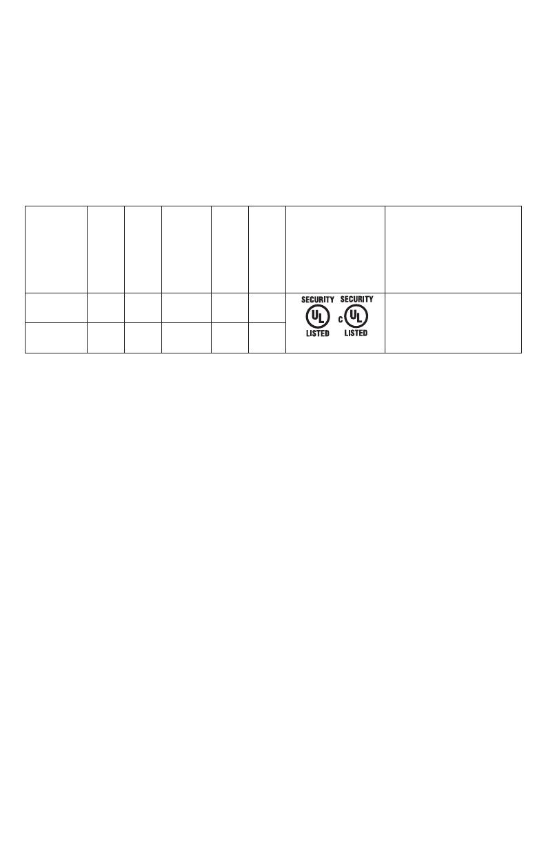
ACM8 and ACM8CB Series Configuration Reference Chart:
Altronix
Model
Number
Number
of Outputs
Fuse Protected
Outputs
PTC Protected
Auto-Resettable
Outputs
Output
Ratings
Class 2 Rated
Power-Limited
Agency Listings
UL Listings and
File Numbers
ACM8 8P 3.5A * UL File # BP6714
UL Listed for Access Control
System Units (UL 294**).
“Signal Equipment” Evaluated to CSA
Standard C22.2 No.205-M1983
ACM8CB 8 – P2.5A P
*When used with Class 2 Rated Power-Limited power supply.
**Access Control Performance Levels: Destructive Attack - I; Endurance - IV; Line Security - I; Stand-by Power - I.
Specifications:
12 to 24 volt DC operation (setting not required).
(0.5A @ 12 volt, 0.3A @ 24 volt current consumption with all relays energized).
Power supply input options:
a) One (1) common power input (board and lock power).
b) Two (2) isolated power inputs (one (1) for board power and one (1) for lock/hardware power).
Eight (8) Access Control System trigger inputs:
a) Eight (8) normally open (NO) inputs.
b) Eight (8) open collector sink inputs.
c) Any combination of the above.
Eight (8) independently controlled outputs:
a) Eight (8) Fail-Safe and/or Fail-Secure power outputs.
b) Eight (8) dry form “C” 5A rated relay outputs.
c) Any combination of the above.
Eight (8) auxiliary power outputs (unswitched).
Output ratings:
- Fuses are rated 3.5A each.
- PTCs are rated 2.5A each.
Main fuse is rated at 10A.
Note: Total output current is determined by the power supply, not to exceed a maximum of 10A total.
Red LEDs indicate outputs are triggered (relays energized).
• Fire Alarm disconnect (latching or non-latching) is individually selectable for any or all of the eight (8) outputs.
Fire Alarm disconnect input options:
a) Normally open [NO] or normally closed [NC] dry contact input.
b) Polarity reversal input from FACP signaling circuit.
FACP output relay (form “C” contact rated @ 1A/28VDC, not evaluated by UL).
Green LED indicates when FACP disconnect is triggered.
Removable terminal blocks facilitate ease of installation.
Board Dimensions (L x W x H): 7.65” x 4.125” x 1.25” (194.3mm x 104.8mm x 31.8mm)
Board fits 6.7” x 3.7” (170.2mm x 94mm) and 4.9” x 2.4” (124.5mm x 64mm) mounting patterns.
Mounting Holes’ Tolerance: +/– 0.04 in. (1mm).
Sub-Assembly
ACM8/CB Sub-Assembly Installation Guide - 3 -
Installation Instructions:
Wiring methods shall be in accordance with the National Electrical Code/NFPA 70/NFPA 72/ANSI, and with all
local codes and authorities having jurisdiction. Product is intended for indoor use only and should be installed by
qualified personnel.
1. Refer to Sub-Assembly Installation Instruction for mounting Rev. MS020119.
Carefully review:
Typical Application Diagram (pg. 5) Terminal Identification Table (pg. 4)
LED Diagnostics (pg. 4) Hook-up Diagrams (pg. 6-7)
2. Power supply input:
The units can be powered with one (1) power supply which will provide power for both board operation and
the locking devices or two (2) separate power supplies, one (1) to provide power for the board operation and
the other to provide power for the locking devices and/or access control hardware.
Note: The input power can be 12 to 24 volts DC (0.5A @ 12 volt, 0.3A @ 24 volt current consumption with
all relays energized).
(a) Single power supply input:
If the unit and the locking devices are to be powered using a single power supply, connect the output
(12 to 24 volts DC) to the terminals marked [– Power +].
(b) Dual power supply inputs (Fig. 1c, pg. 4):
When the use of two power supplies is desired, jumpers J1 and J2 (located to the left of the power/
control terminals) must be cut. Connect power for the unit to the terminals marked [– Control +] and
connect power for the locking devices to the terminals marked [– Power +].
Note: When using DC power supplies polarity must be observed. When using AC power supplies polarity
needs not to be observed (Fig. 1d, pg. 4). AC applications not evaluated by UL.
Note: For UL compliance the power supplies must be UL Listed for Access Control Systems and accessories.
3. Output options (Fig. 1, pg. 4):
The ACM8 will provide either eight (8) switched power outputs, eight (8) dry form “C” outputs, or any
combination of both switched power and form “C” outputs, plus eight (8) unswitched auxiliary power outputs.
The ACM8CB will provide eight (8) switched power outputs or eight (8) unswitched auxiliary power outputs.
(a) Switched Power outputs:
Connect the negative (–) input of the device being powered to the terminal marked [COM].
For Fail-Safe operation connect the positive (+) input of the device being powered to the terminal
marked [NC].
For Fail-Secure operation connect the positive (+) input of the device being powered to the terminal
marked [NO].
(b) Form “C” outputs:
When form “C” outputs are desired the corresponding output fuse (1-8) must be removed (ACM8 only).
Connect negative (–) of the power supply directly to the locking device. Connect the positive (+) of the
power supply to the terminal marked [C].
For Fail-Safe operation connect the positive (+) input of the device being powered to the terminal
marked [NC].
For Fail-Secure operation connect the positive (+) input of the device being powered to the terminal
marked [NO].
(c) Auxiliary Power outputs (unswitched):
Connect positive (+) input of the device being powered to the terminal marked [C] and the negative (–)
of the device being powered to the terminal marked [COM]. Output can be used to provide power for
card readers, keypads etc.
4. Input trigger options (Fig. 1, pg. 4):
(a) Normally Open [NO] input trigger:
Inputs 1-8 are activated by normally open or open collector sink inputs.
Connect devices (card readers, keypads, request to exit buttons etc.) to terminals marked [IN] and [GND].
(b) Open Collector Sink inputs:
Connect the access control panel open collector sink positive (+) to the terminal marked [IN] and the
negative (–) to the terminal marked [GND].
- 4 - ACM8/CB Sub-Assembly Installation Guide
5. Fire Alarm Interface options (Figs. 3 through 7, pg. 6-7):
A normally closed [NC], normally open [NO] input or polarity reversal input from FACP signaling circuit will
trigger selected outputs. To enable FACP Disconnect for an output turn the corresponding switch
[SW1- SW8] OFF. To disable FACP disconnect for an output turn the corresponding switch [SW1-SW8] ON.
(a) Normally Open [NO] input:
For non-latching hook-up (Fig. 4, pg. 6). For latching hook-up (Fig. 5, pg. 6).
(b) Normally Closed [NC] input:
For non-latching hook-up (Fig. 6, pg. 7). For latching hook-up (Fig. 7, pg. 7).
(c) FACP Signaling Circuit input trigger:
Connect the positive (+) and negative (–) from the FACP signaling circuit output to the terminals
marked [+ INP –].
Connect the FACP EOL to the terminals marked [+ RET –] (polarity is referenced in an alarm condition).
Jumper located next to TRG LED must be cut (Fig. 1a, pg. 4).
6. FACP Dry form “C” output (Fig. 1b, pg. 4):
Connect desired device to be triggered by the unit’s dry contact output to the terminals marked [NO] and [C]
FACP for normally open output or the terminals marked [NC] and [C] FACP for normally closed output.
Note: This product is a UL Listed Sub-Assembly for use with Altronix UL Listed power supplies as indicated
in the installation manuals for the power supply.
LED Diagnostics:
ACM8 and ACM8CB Access Power Controller
LED ON OFF
LED 1- LED 8 (Red) Output relay(s) energized. Output relay(s) de-energized.
Trg (Green) FACP input triggered (alarm condition). FACP normal (non-alarm condition).
Terminal Identification Tables:
ACM8 and ACM8CB Access Power Controller
Terminal Legend Function/Description
Power + 12VDC or 24VDC input from power supply board.
Control + These terminals can be connected to a separate UL Listed power supply to provide
isolated operating power for the ACM8/ACM8CB (jumpers J1and J2 must be removed).
TRIGGER
INPUT 1 - INPUT 8
IN, GND
From normally open and/or open collector sink trigger inputs
(request to exit buttons, exit pir’s, etc.).
OUTPUT 1 - OUTPUT
8
NC, C, NO, COM
12 to 24 volts AC/DC trigger controlled outputs:
Fail-Safe [NC positive (+) & COM Negative (–)],
Fail-Secure [NO positive (+) & COM Negative (–)],
Auxiliary output [C positive (+) & COM Negative (–)]
(When using AC power supplies polarity need not be observed),
NC, C, NO become form “C” 5A/24VAC/VDC rated dry outputs when fuses are
removed (ACM8). Contacts shown in a non-triggered state.
FACP INTERFACE
T, + INPUT –
Fire Alarm Interface trigger input from FACP. Trigger inputs can be normally open,
normally closed from an FACP output circuit (Fig. 3 through 7, pgs. 6-7).
FACP INTERFACE
NC, C, NO
Form “C” relay contact rated @ 1A 28VDC for alarm reporting.
(This output has not been evaluated by UL).
ACM8/CB Sub-Assembly Installation Guide - 5 -
Typical Application Diagram:
NC
NO
C
Normally Open (N.O.)
Door Releasing
Device
Access Control Panel
Output
Relay
Mag.
Lock
MAG. LOCK
Electric
Strike
Electromagnetic
Door Holders
AC or DC
Power
Supply
(req'd.)
FACP
(Fire Alarm
Control
Panel)
AC or DC
Power
Supply
(optional)
UL Listed
Power Supply
For this application
corresponding
fuse F8 must be
removed.
ACM8CBACM8
LED1
F1
3.5A 250V
LED1
2A 250V
Keypad
NC C NO COM
OUTPUT 1
LED1
F1
NC C NO COM
OUTPUT 2
IN GND
1
IN GND
2
IN GND
3
IN GND
4
IN GND
5
IN GND
6
IN GND
7
MAIN
IN GND
8
LED2 LED3 LED4 LED5 LED6 LED7 LED8
J2
TRG
FACP
NC C NO COM
OUTPUT 3
NC C NO COM
OUTPUT 4
NC C NO COM
OUTPUT 5
NC C NO COM
OUTPUT 6
NO C NC + INP --- T + RET -
NC C NO COM
OUTPUT 7
NC C NO COM
OUTPUT 8
--- +
Power
--- +
Control
F2 F3 F6 F7 F8
F4 F5
J1
J3
FACP INTERFACE
10A 250V
FACP Dry
Form "C" Output
NO C NC
FACP
1 2 3 4
ON
1 2 3 4
ON
Enabled
Disabled
FACP Interface
SW1-SW8
ON
1
ON
1
J2
--- +
Control
J1
Intact = One P/S Input
Cut = Dual P/S Input
NC C NO COM
OUTPUT 8
J3
Intact = DC Input
Cut = AC Input
LED1 LED2 LED3 LED4 LED5 LED6 LED7 LED8
TRG
FACP
Intact = Dry Input
Cut = Wet Input
Fig. 1
Fig. 1b
WARNING: To reduce the risk of fire or electric shock, do not expose the unit to rain or moisture.
Replace fuses (ACM8 only) with the same type and rating, 3.5A/250V.
Fig. 1a
Fig. 1cFig. 1d
- 6 - ACM8/CB Sub-Assembly Installation Guide
Hook-Up Diagrams:
Fig. 4 Normally Open: Non-Latching FACP trigger input:
Fig. 3 Polarity reversal input from FACP signaling circuit output (polarity is referenced in alarm condition):
Fig. 2 Optional hook-up using two (2) isolated power supply inputs:
J2 J1
CUT JUMPERS
J1 AND J2
ISOLATED POWER INPUT
12 OR 24 VAC OR VDC
(LOCK POWER)
ISOLATED POWER INPUT
12 OR 24 VAC OR VDC
(ACM8 POWER)
CUT
JUMPER
FROM FACP
OUTPUT
CIRCUIT
+
--
FACP
OUTPUT EOL
TRG
FACP
NO C NC
FACP INTERFACE
N.O. TRIGGER
INPUT
TRG
FACP
NO C NC
FACP INTERFACE
ACM8/CB Sub-Assembly Installation Guide - 7 -
JUMPER
N.C. DR
Y
TRIGGER
INPUT
TRG
NO C NC
FACP INTERFACE
FACP
N.C. TRIGGER
INPUT
N.C. RESET
SWITCH
JUMPER
TRG
FACP
Fig. 6 Normally Closed: Non-Latching FACP trigger input:
Fig. 7 Normally Closed: Latching FACP trigger input with reset (This output has not been evaluated by UL):
Fig. 5 Normally Open FACP Latching trigger input with reset (This output has not been evaluated by UL):
N.C. RESET
SWITCH
N.O.
TRIGGER
INPUT
JUMPER
TRG
NO C NC
FACP
Hook-Up Diagrams:
- 8 - ACM8/CB Sub-Assembly Installation Guide
Notes:
Altronix is not responsible for any typographical errors.
––––––––––––––––––––––––––––––––––––––––––––––––––––––––––––––––––––––––––––––––––––––––––––––––––––––––––––––––
140 58th Street, Brooklyn, New York 11220 USA | phone: 718-567-8181 | fax: 718-567-9056
website: www.altronix.com | e-mail: [email protected] | Lifetime Warranty
IIACM8/ACM8CB L14V MEMBER
  • Page 1 1
  • Page 2 2
  • Page 3 3
  • Page 4 4
  • Page 5 5
  • Page 6 6
  • Page 7 7
  • Page 8 8

Altronix ACM8 User manual

Type
User manual

Altronix ACM8 is an Access Power Controller that converts one 12 to 24 volt DC input into eight independently controlled fused or PTC protected outputs. These outputs can be converted to dry form “C” contacts. The device can be used to power various access control devices, including mag locks, electric strikes, and magnetic door holders. It also features a Fire Alarm disconnect and a FACP Interface for Emergency Egress and Alarm Monitoring.

Ask a question and I''ll find the answer in the document

Finding information in a document is now easier with AI