Page is loading ...

716 OUTPUT EXPANSION MODULE
Installation Guide
DESCRIPTION
MODEL
716
TXD
NS
2
NC
NO
C
3
NC
NO
C
4
NC
NO
C
1
NC
1
12 VDC
12 VDC
12 VDC
12 VDC
2
3
4
NO
C
0
1
2
3
4
5
6
7
8
9
0
1
2
3
4
5
6
7
8
9
T
E
N
S
O
N
E
S
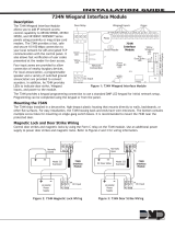
The 716Output Expansion Module
provides four independently
programmable Form C (SPDT)
relays and four zone‑following
annunciator outputs for use on
XR150/XR550Series panels.
Connect the 716Module to the
panel LX‑Bus. The 716Module
cannot be connected to the Keypad
Bus.
In addition to the panel onboard
Form C relays, you can connect
multiple modules to the panel
for unique auxiliary relays
and annunciator outputs,
one per zone. The XR550has
500available LX‑Bus zones. The
XR150has100available LX‑Bus
zones.
Compatibility
• XR150/XR550Panels
What is Included?
• One 716Output Expansion
Module
• One 20‑Wire Harness
• Hardware Pack
1
MOUNT THE MODULE
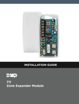
The716comes in a high‑impact plastic housing that you can
mount directly to a wall, backboard, or other flat surface. For easy
installation, the housing base contains holes that allow you to
mount themodule on a single‑gang switch box or ring. Mount the
module outside the panel enclosure.
1. Remove the housing fastener screws and separate the top
housing from the base.
2. Insert screws through the desired mounting holes on the
housing base. Refer to Figure 2for mounting hole locations.
3. Tighten the screws into place.
4. Attach the housing top to the mounted base with the
housing fastener screws. Refer to Figure 3.
Figure 1: 716 Module
Mounting
holes
Housing Base
Housing
fastener
hole
Housing
fastener
hole
Figure 2: Mounting Hole Locations
Figure 3: Assembling the Housing

2 716 INSTALLATION GUIDE | DIGITAL MONITORING PRODUCTS
3
Set the 716Module to an address that is used by the panel to turn outputs on and o. For easy addressing,
the716contains two on‑board rotary switches that you can set with a small screwdriver.
When using annunciator outputs, set the 716address to match the zones that you want the outputs to follow.
If you are only using the Form C relays, set the address to match the output numbers that you want to operate.
The module uses two rotary switches (TENS and ONES) to set the module address. Set the switches to match
the last two digits of the addresses. For example, for address 02set the switches to TENS 0and ONES 2 as
shown in Figure 4. For more information, refer to Table 1.
Note: Any 711, 714, 714‑8, 714‑16, 714‑8INT, 714‑16INT, 715, or other LX‑Bus device can be set to the same
address as a 716that is operating in unsupervised mode. Sharing an LX‑Bus address in this manner does
not cause a conflict between these devices. For more information, refer to “Unsupervised Operation”.
SWITCH
TENS ONES
XR150SERIES XR550SERIES
LX500 LX500 LX600 LX700 LX800 LX900
0 0 500 500 600 700 800 900
0 1 501 501 601 701 801 901
0 2 502 502 602 702 802 902
0 3 503 503 603 703 803 903
0 4 504 504 604 704 804 904
... ... ... ... ... ... ... ...
9 5 595 595 695 795 895 995
9 6 596 596 696 796 896 996
9 7 597 597 697 797 897 997
9 8 598 598 698 798 898 998
9 9 599 599 699 799 899 999
Table 1: LX‑Bus and Corresponding Zone Numbers
SET THE MODULE ADDRESS
WIRE THE MODULE
2
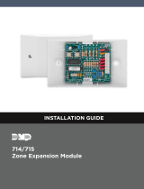
Refer to Figure 4when wiring the module. Connect the included20‑wire harness to the main header. Connect
red, green, and black wires to the panel LX‑Bus. For supervised operation, connect the yellow wire to the panel
LX‑Bus. Connect remaining wires as needed. For more information, refer to “Unsupervised Operation” and
“Supervised Operation”.
MODEL
716
TXD
1
NC
R
Y
G
B
NO
3
NC
NO
4
NC
NO
White/Brown
White/Red
White/Orange
White/Yellow
Switched Grounds (1 to 4)
Positive Voltage
50 VDC @ 50 mA max
To LX-Bus
RED
YELLOW
GREEN
BLACK
To Relay 1
To Relay 2
To Relay 3
To Relay 4
C
C
2
NC
NO
C
C
Relay Contacts
1 Amp @ 30 VDC
Data LED
Address
Switches
NC
NO
C
NC
NO
C
NC
NO
C
NC
NO
C
NS
1
2
3
4
0
1
2
3
4
5
6
7
8
9
0
1
2
3
4
5
6
7
8
9
T
E
N
S
O
N
E
S
7 mA + 28 mA
per active relay
Optional LED
Figure 4: Module Wiring

716 INSTALLATION GUIDE | DIGITAL MONITORING PRODUCTS 3
PROGRAM THE PANEL
Assign the Form C relays to outputs in Output Options and Zone Information, or assign the relays to Zone
Alarm Actions. For example, program the panel Telephone Trouble Output to operate output 520so that a
trouble on the panel phone line would toggle relay 1on a module set to address 520. Output 521would toggle
relay 2on the same 716module. The module’s four Form C relays are rated for 1Amp at 30VDC resistive. For
more information about programming, refer to the appropriate panel programming guide.
4
ADDITIONAL INFORMATION
Wiring Specifications
DMP recommends using 18 or 22 AWG for all LX‑Bus and Keypad Bus connections. The maximum wire distance between
any module and the DMP Keypad Bus or LX‑Bus circuit is 10 feet. To increase the wiring distance, install an auxiliary
power supply, such as a DMP Model 505‑12. Maximum voltage drop between a panel or auxiliary power supply and any
device is 2.0 VDC. If the voltage at any device is less than the required level, add an auxiliary power supply at the end of
the circuit.
To maintain auxiliary power integrity when using 22‑gauge wire on Keypad Bus circuits, do not exceed 500 feet. When
using 18‑gauge wire, do not exceed 1,000 feet. Maximum distance for any bus circuit is 2,500 feet regardless of wire
gauge. Each 2,500 foot bus circuit supports a maximum of 40 LX‑Bus devices.
For additional information refer to the LX‑Bus/Keypad Bus Wiring Application Note (LT‑2031) and the 710 Bus Splitter/
Repeater Module Installation Guide (LT‑0310).
Supervised Operation
To install the module as a supervised device, connect all four LX‑Bus wires from the module to the panel LX‑Bus and
program an appropriate zone as a Supervisory (SV) type. The module may use any address for supervision, provided
that a Supervisory zone is programmed for that address. For example, zone 504on an XR550Series panel would be
programmed as an SV zone to supervise a 716module set to address 04on the first LX‑Bus. Only the first zone number
for the programmed device is supervised. Refer to Table 1.
When installing Zone Expansion Modules on the same LX‑Bus as a supervised 716Module, address the Zone Expanders
to the next zone number. For example, on an XR550Series panel, the zone is 520for supervision and 521for a zone
expander on the same bus.
If a supervised 716Module loses communication with the panel, an open condition (Trouble) is indicated on its
Supervisory zone.
Unsupervised Operation
To operate the module in unsupervised mode, do not connect the yellow wire from the module to the panel LX‑Bus.
Unsupervised operation allows you to install multiple modules and set them to the same address. Do not program a
zone address for unsupervised operation. Unsupervised operation is incompatible with fire listed installations. For more
information, refer to “Compliance Listing Specifications”.
Annunciator Outputs (Switch‑to‑Ground)
Unlike the module Form C relays, the four power limited annunciator outputs on the 716Module follow the zone state
having the same address. For example, output 1 (white/brown) on a 716module set to address 120shorts to ground each
time zone 120is in alarm or trouble while armed. Use this feature to operate relays or LEDs to show changes in the state
of the panel armed zones. Refer to Table 2.
ARMED ZONE STATE 716ANNUNCIATOR OUTPUT ACTION
Normal O—No ground reference
Trouble, wireless low battery, missing On—Steady short to ground
"A" or "L" in Report to Transmit Pulse (1.6seconds On, 1.6seconds O)
Zone Bypassed Slow pulse (1.6seconds On, 4.8seconds O)
Table 2: Annunciator Outputs

Designed, engineered, and
manufactured in Springfield, MO
using U.S. and global components.
LT-0183 1.03 20105
716 OUTPUT
EXPANSION MODULE
Specifications
Operating Voltage 12 VDC Nominal
Current Draw
Standby 13 mA
Operating 13 mA
+ 12 mA per active relay
Weight 4.8 oz. (136.0 g)
Dimensions 2.5” W x 2.5” H (6.35 cm W x 6.35 cm H)
Ordering Information
716 Output Expansion Module
Compatibility
XR150/XR550 Series Panels
Certifications
California State Fire Marshall (CSFM)
New York City (FDNY COA #6167)
Underwriters Laboratory (UL) Listed
ANSI/UL 365 Police Connected Burglar
ANSI/UL 464 Audible Signal Appliances
ANSI/UL 609 Local Burglar
ANSI/UL 864 Fire Protective Signaling
ANSI/UL 985 Household Fire Warning
ANSI/UL 1023 Household Burglar
ANSI/UL 1076 Proprietary Burglar
ULC Subject-C1023 Household Burglar
ULC/ORD-C1076 Proprietary Burglar
ULC S304 Central Station Burglar
ULC S545 Household Fire
MODEL
716
TXD
NS
2
NC
NO
C
3
NC
NO
C
4
NC
NO
C
1
NC
1
12 VDC
12 VDC
12 VDC
12 VDC
2
3
4
NO
C
0
1
2
3
4
5
6
7
8
9
0
1
2
3
4
5
6
7
8
9
T
E
N
S
O
N
E
S
INTRUSION • FIRE • ACCESS • NETWORKS
2500 North Partnership Boulevard
Springfield, Missouri 65803-8877
800.641.4282 | DMP.com
© 2020
Exceptions to Output Expansion Module Addressing
The module can only be wired to an LX‑Bus. To determine the correct output for a particular keypad zone, match the
zone number with the annunciator output number. Special addresses are configured to allow the annunciator outputs to
follow the panel and keypad zones when connected to the first LX‑Bus. Refer to Table 3.
LX‑500
ADDRESS
ZONES
LX‑500
ADDRESS
ZONES
LX‑500
ADDRESS
ZONES
LX‑500
ADDRESS
ZONES
501 1to 4 541 41to 44 519 91‑94 559 131‑134
505 5to 8 551 51to 54 529 101‑104 569 141‑144
509 9to 10 561 61to 64 539 111‑114 579 151‑154
511 11to 14 571 71to 74 549 121‑124 589 161‑164
521 21to 24 581 81to 84
531 31to 34
Table 3: XR150/XR550Series LX‑Bus Addresses and Corresponding Zones
COMPLIANCE LISTING SPECIFICATIONS
UL Listed Installations
To comply with ANSI/UL 365Police‑Connected Burglary System or ANSI/UL 609Local Burglary Alarm Systems, the
module must be mounted in the supplied, UL listed enclosure with a tamper.
Unsupervised operation is not suitable for fire listed installations.
Any auxiliary power supply for a commercial fire installation must be regulated, power limited, and listed for Fire
Protective Signaling.
ULC Commercial Burglary Installations (XR150/XR550Series Panels)
Place the output module with at least one zone expander in a listed enclosure and connect a DMP Model 307Clip‑on
Tamper Switch to the enclosure programmed as a 24‑hour zone.
/