Page is loading ...

Ra ym a rin e
3 3 S TV S a t e llit e
Te le vis io n S y s t e m
US Ve rs ion
Us e r’s Guide
33STVSatelliteTVUser’sGuide


Trademarksandregisteredtrademarks
Autohelm,HSB,RayT echNavigator,SailPilot,SeaTalkandSportpilotareUKregisteredtrademarksofRaymarineUKLimited.
PathnderandRaymarineareUKregisteredtrademarksofRaymarineHoldingsLimited.33STV,45STV ,60STV,AST ,Autoadapt,Auto
GST,AutoSeastate,AutoTrim,Bidata,GSeries,HDFI,LifeTag,MarineIntelligence,Maxiview,OnBoard,Raychart,Raynav,Raypilot,
RayTalk,Raystar,ST40,ST60+,Seaclutter,SmartRoute,Tridata,UniControl,Hybridtouch,andWaypointNavigationaretrademarksof
RaymarineUKLimited.
Allotherproductnamesaretrademarksorregisteredtrademarksoftheirrespectiveowners.
Copyright©2009RaymarineUKLtd.Allrightsreserved.
ENGLISH
Documentnumber:81325-1
Date:09-2009


Contents
Chapter1Introduction.............................................7
Safetynotices.................................................................7
Importantinformation......................................................7
Chapter2Installation...............................................11
2.1Preparation...............................................................12
2.2Procedures...............................................................18
Chapter3Systemoperation&setup......................25
3.1Introduction...............................................................26
3.2Gettingstarted..........................................................26
3.3SetupusingtheACU.................................................28
3.4Applyingfactorydefaultvalues...................................37
3.5Systeminformation...................................................37
3.6Checkingsystempower.............................................38
3.7Skewangle...............................................................38
3.8Graphicaluserinterface.............................................39
Chapter4Maintenance&troubleshooting............41
4.1Maintenance.............................................................42
4.2Troubleshooting........................................................42
4.3Raymarinetechnicalsupport......................................44
Chapter5Satelliteinformation...............................45
5.1Introduction...............................................................46
5.2Satellitecoverage.....................................................46
5.3Satelliteproviders.....................................................47
5.4Satellitetrackingdata................................................49
Chapter6TechnicalSpecication..........................55
6.1Technicalspecication...............................................56
5

633STVSatelliteTVUser’sGuide

Chapter1:Introduction
Safetynotices
Warning:Productinstallationand
operation
Thisproductmustbeinstalledandoperatedin
accordancewiththeRaymarineinstructionsprovided.
Failuretodosocouldresultinpersonalinjury,damage
toyourboatand/orpoorproductperformance.
Caution:Powersupplyprotection
Wheninstallingthisproductensurethepower
sourceisadequatelyprotectedbymeansofa
suitably-ratedfuseorautomaticcircuitbreaker.
Caution:Usecorrectliftingpoint
Whenliftingtheantennaunit,alwaysliftfromthe
baseplate.DoNOTusetheantennacoveror
damagetothecovercouldoccur.
Caution:Donotdamageconnectors
Takecaretoavoiddamagetotheconnectors
underneaththeantennabaseplatewhenmoving
theunit.DoNOTusetheseconnectorstoliftthe
unit.
Caution:Removetransitpacking
Beforeinstallingoroperatingtheproduct,open
theantennaunitcoverandremovethefoam
transitpackinginsertsfromtheunitbase.
Caution:Antennacoating
DoNOTpaintorapplyanyothernishtothe
antennaunit.Thiscoulddegradeperformance
beyondacceptablelimits.
Importantinformation
Handbookinformation
D1174 0-1
Thishandbookdescribeshowtoinstall,operateandmaintainthe
Raymarine33SatelliteTelevision(33STV)system.
Whileoutatseaordocked,theRaymarineSatelliteTVsystem
automaticallyidenties,acquiresandtrackscompatiblesignalsfrom
Introduction
7

alldigitalvideobroadcast(DVB)satellites.Thisprovidesaccessto
hundredsofTVchannels.
Pleasecarefullyreadandfollowtheinstallation,operatingand
maintenanceprocedures.
IMOandSOLAS
Theequipmentdescribedwithinthisdocumentisintendedforuse
onleisuremarineboatsandworkboatsnotcoveredbyInternational
MaritimeOrganization(IMO)andSafetyofLifeatSea(SOLAS)
CarriageRegulations.
Geographiclocation
SatellitesoutsideofNorthAmericatransmitsignalsonalinear
polarization,thismeanssignalsaretransmittedhorizontallyand
vertically.SatellitescoveringNorthAmericatransmitcircularly
polarizedsignalsthatrotate.Iftherotationisclockwisetowardsthe
directionofpropagation,itiscalledright-hand-circular(RHC).Ifthe
rotationiscounterclockwise,itiscalledleft-hand-circular(LHC).
Youcannotreceivesignalsthathavelinearpolarizationonasystem
thatissetupforcircularpolarization,orvice-versa.
TheSTVSystemwillreceivesignalsfromselectedsatellitesinthe
followingareas.
Circularpolarization:
•NorthAmerica
Linearpolarization:
•Europe
•Australia
•NewZealand
•China
•MiddleEast
Uptodatecoveragemapsandsatelliteinformationarefoundby
navigatingtothehomepageofthesatelliteserviceproviders.
Ifyouchangeyourareaofoperation,youmayneedtochangesome
settingsonyourSTVsystem:
•Ifyourgeographiclocationchanges,youmayneedto:
–Adjusttheantennalownoiseblock(LNB)asappropriateforthe
areainwhichyouareoperating.
–Changeyourcontrolboard,ACUsoftwareandsatellite
receivers(IRDs).
Forfulldetailsofchangingyourgeographicareaofoperation,
contactRaymarineProductSupport.
Televisionreception
ForfullfunctionalityofyourSTVSystem,youmustsubscribetothe
relevantservice(s)fromtheappropriateserviceprovider(s).Full
detailsofserviceprovidersaregiven.
EMCconformance
Raymarineequipmentandaccessoriesconformtotheappropriate
ElectromagneticCompatibility(EMC)regulationsforuseinthe
recreationalmarineenvironment.
CorrectinstallationisrequiredtoensurethatEMCperformanceis
notcompromised.
Declarationofconformity
ThisproductconformswithEUDirective2004/108/ECandis
labelledwiththeCEconformitymark.
833STVSatelliteTVUser’sGuide

Productdisposal
DisposeofthisproductinaccordancewiththeWEEEDirective.
TheWasteElectricalandElectronicEquipment(WEEE)
Directiverequirestherecyclingofwasteelectricalandelectronic
equipment.WhilsttheWEEEDirectivedoesnotapplytosome
Raymarineproducts,wesupportitspolicyandaskyoutobeaware
ofhowtodisposeofthisproduct.
Warrantyregistration
ToregisteryourRaymarineproductownership,pleasetakeafew
minutestolloutthewarrantyregistrationcardfoundinthebox,or
visitwww.raymarine.comandregisteron-line.
Itisimportantthatyouregisteryourproducttoreceivefullwarranty
benets.Yourunitpackageincludesabarcodelabelindicatingthe
serialnumberoftheunit.Youshouldstickthislabeltothewarranty
registrationcard.
Technicalaccuracy
Tothebestofourknowledge,theinformationinthisdocumentwas
correctatthetimeitwasproduced.However,Raymarinecannot
acceptliabilityforanyinaccuraciesoromissionsitmaycontain.In
addition,ourpolicyofcontinuousproductimprovementmaychange
specicationswithoutnotice.Asaresult,Raymarinecannotaccept
liabilityforanydifferencesbetweentheproductandthisdocument.
Introduction9

1033STVSatelliteTVUser’sGuide

Chapter2:Installation
Chaptercontents
•2.1Preparationonpage12
•2.2Proceduresonpage18
Installation
11

2.1Preparation
EMCinstallationguidelines
Raymarineequipmentandaccessoriesconformtotheappropriate
ElectromagneticCompatibility(EMC)regulations,tominimize
electromagneticinterferencebetweenequipmentandminimizethe
effectsuchinterferencecouldhaveontheperformanceofyour
system
CorrectinstallationisrequiredtoensurethatEMCperformanceis
notcompromised.
ForoptimumEMCperformancewerecommendthatwherever
possible:
•Raymarineequipmentandcablesconnectedtoitare:
–Atleast1m(3ft)fromanyequipmenttransmittingorcables
carryingradiosignalse.g.VHFradios,cablesandantennas.
InthecaseofSSBradios,thedistanceshouldbeincreased
to7ft(2m).
–Morethan2m(7ft)fromthepathofaradarbeam.Aradar
beamcannormallybeassumedtospread20degreesabove
andbelowtheradiatingelement.
•Theproductissuppliedfromaseparatebatteryfromthatused
forenginestart.Thisisimportanttopreventerraticbehavior
anddatalosswhichcanoccuriftheenginestartdoesnothave
aseparatebattery.
•Raymarinespeciedcablesareused.
•Cablesarenotcutorextended,unlessdoingsoisdetailedin
theinstallationmanual.
Note:Whereconstraintsontheinstallationpreventanyof
theaboverecommendations,alwaysensurethemaximum
possibleseparationbetweendifferentitemsofelectrical
equipment,toprovidethebestconditionsforEMCperformance
throughouttheinstallation
Suppressionferrites
Raymarinecablesmaybettedwithsuppressionferrites.These
areimportantforcorrectEMCperformance.Ifaferritehastobe
removedforanypurpose(e.g.installationormaintenance),itmust
bereplacedintheoriginalpositionbeforetheproductisused.
Useonlyferritesofthecorrecttype,suppliedbyRaymarine
authorizeddealers.
Connectionstootherequipment
Requirementforferritesonnon-Raymarinecables
IfyourRaymarineequipmentistobeconnectedtootherequipment
usingacablenotsuppliedbyRaymarine,asuppressionferrite
MUSTalwaysbeattachedtothecableneartheRaymarineunit.
Partssupplied
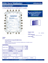
Thefollowingpartsareprovidedfora33STVsystem:
•AntennaUnit
•AntennaControlUnit(ACU)
•InstallationKitcomprising:
–Bolts
–Flatwashers
–Springwashers
–Selftappingscrews
•Cablesasfollows:
12
33STVSatelliteTVUser’sGuide

–R08321-10mPowercable-usedforconnectingtheACUto
theDCpowersupply.
–R08257-3mRFcable-usedforconnectingtheACUand
IntegratedReceiverDecoder(IRD)
–R08135-15mRFcable-usedforconnectingtheAntenna
andACU.
–R42173-1.5mUSBABTypePCcable-usedforconnecting
theACUtoaPCforsystemsetupanddiagnostic.
–R42174-1.8mUSBAMtoAMTypecable-usedforconnecting
theACUtoIRD(OnlycompatiblewithDIRECTVreceiver).
•CDROM-contains:
–SoftwareforrunningtheSTVGraphicalUserInterface(GUI)
onapersonalcomputer(PC).
–Productusermanual,asPDF.
Toolsrequired
Toolsnecessaryforinstallation.
Power drill
11 mm (7/16 in)
socket
8 mm (5/16 in)
drill
10 mm (3/8 in)
spanner
11 mm (7/16 in)
spanner
Socket wrench
50 mm (2 in)
hole saw
Pencil
Adhesive tape
Cross-head
screwdriver
5 mm
Allen key
D117 35 -1
Installation13

Planning
Antennaunit
RF 2RF 1
Bas e plate
conne ctor deta il
Antenna Unit
D
1
1
736 -1
TheAntennaunitcomprisestheantennadish,positioning
mechanism,lownoiseblock(LNB),powersupplyandcontrol
elementsinamoldedradome.
Connectorsontheundersideofthebaseplateconnectthepower,
signalandcontrolcablingfromthebelowdecksunits.
Forconnectiondetails,refertotheinstallationprocedures.
AntennaControlUnit(ACU)
TheAntennaControlUnit(ACU)providesallcontroland
power-switchingfunctionsfortheantenna.Threesoftkeysenable
satelliteprogrammingandantennadiagnosticstobecarriedout.
D11531-1
Twobuttonsattheright-handsideofthefrontpanelareusedwith
somesetupprocedurestoprovideBACKandENTERfunctions.
TheACUrearconnectorsare:
•DC9to30Vforpowerinput.
•ANTRF1-connectspowerandsignaltotheantenna.
•NMEA-connectstoGPS(optional).
•PCINTERFACE-connectstoPCforremoteoperationfroma
computer(optional).
•RECEIVER-connectstothesatellitereceiver(notsupplied).
ANT RF1
FUSEDC 9 to 30V NMEA PC INTERFACE
RECEIVER
-
+
-
+
MADE IN KOREA
D11728-2
RECEIVER USB PORT
Forconnectiondetails,refertotheinstallationprocedures.
14
33STVSatelliteTVUser’sGuide

Antennaposition
Clear view of sky
D11449-1
Theantenna,mustbeinstalledwhere:
•Thereisanallroundclearviewofthehorizon.
•Itisnottoohighabovethewater-themaximumrecommended
heightisonenotexceedinghalfthelengthoftheboat.
•Itisasnearaspossibletothecenterlineoftheboat.
•Onarigidmountingplatformthatisnotsubjecttoexcessive
vibration.
•Awayfromtheedgeoftheboat.Thiswillminimizeexcessive
motion,whichcanadverselyaffectreception.
•Clearofanyradarbeam.Thiscouldadverselyaffectantenna
operation.
Above the beam
Below the beam
In the
beam
Min 1.2 m (4 ft)
Min 1.2 m (4 ft)
D7950_1
•Clearofanyobjectwhichcouldblockthesatellitesignal.Ensure
thereisa+15°to+90°lookangleattheintendedinstallation
position.
+15
90
0
0
Mast
Blocked!
D7951_1
ACUinstallation
TheACUmustbettedbelowdecksinapositionthatis:
•Dry.
•Wellventilated.
•Easilyaccessible.
•NeartothemainTVviewingarea.
Installation15

ACUdimensions
228 mm (9.0 in)55 mm
(2.2 in)
185 mm (7.3 in)
D11550-1
217 mm (8.5 in)
178 mm (7.0 in)
Routingcables
Cablesmustberoutedcorrectly,tomaximizeperformanceand
prolongcablelife.
•DoNOTbendcablesexcessively.Whereverpossible,ensurea
minimumbendradiusof100mm.
Minimum bend of cable
100 mm (4 in) radius
Minimum bend
200 mm (8 in)
diameter
•Protectallcablesfromphysicaldamageandexposuretoheat.
Usetrunkingorconduitwherepossible.DoNOTruncables
throughbilgesordoorways,orclosetomovingorhotobjects.
•Securecablesinplaceusingtie-wrapsorlacingtwine.Coilany
extracableandtieitoutoftheway.
•Whereacablepassesthroughanexposedbulkheadordeckhead,
useasuitablewatertightfeed-through.
•DoNOTruncablesneartoenginesoruorescentlights.
Alwaysroutedatacablesasfarawayaspossiblefrom:
•otherequipmentandcables,
•highcurrentcarryingacanddcpowerlines,
•antennae.
PowerRequirements
ARaymarine33STVsystemneedseithera12Vdcor24Vdc
powersupply.
IftheIRD(s)andtelevision(s)requirea220/240Vacpowersupply,
asuitabledc-to-acconvertermustbetted,toprovidethenecessary
powerfromtheboat’sdcpowersupply.
Grounding
ThesegroundingrequirementsareapplicableforRaymarine
equipmentsuppliedwithaseparatedrainwireorscreen.
1633STVSatelliteTVUser’sGuide

•Theproductpowercabledrainconductor(screen)mustbe
connectedtoacommongroundpoint.
•Itisrecommendedthatthecommongroundpointisabonded
ground,i.e.withthegroundpointconnectedtobatterynegative,
andsituatedascloseaspossibletothebatterynegativeterminal.
Ifabondedgroundsystemisnotpossible,anon-bondedRF
groundmaybeused.
Bondedgroundsystem(preferred)
D117 09-1
1 2 4
3
RFgroundsystem(alternative)
D117 10-1
1 2 4
3
1.Powercabletoproduct
2.Drain(screen)
3.Bonded(preferred)ornon-bondedRFground.
4.Battery
Implementation
Ifseveralitemsrequiregrounding,theymayrstbeconnected
toasinglelocalpoint(e.g.withinaswitchpanel),withthispoint
connectedviaasingle,appropriately-ratedconductor,totheboat’s
commonground.Thepreferredminimumrequirementforthepath
toground(bondedornon-bonded)isviaaattinnedcopperbraid,
witha30Arating(1/4inch)orgreater.Ifthisisnotpossible,an
equivalentstrandedwireconductormaybeused,ratedasfollows:
•forrunsof<1m(3ft),use6mm
2
(#10AWG)orgreater.
•forrunsof>1m(3ft),use8mm
2
(#8AWG)orgreater.
Inanygroundingsystem,alwayskeepthelengthofconnecting
braidorwiresasshortaspossible.
Important:DoNOTconnectthisproducttoapositively-grounded
powersystem.
References
•ISO10133/13297
•BMEAcodeofpractice
•NMEA0400
Extendingcableruns
Note:Systemperformancewillbereducedifsuppliedcables
areextended.
Installation
17

IftheRFcablesuppliedasstandardisnotlongenough,a
98ft(30m)cable,isavailablefromyourRaymarinedealer,
(partnumberE96008).Connectthelongercabletothesupplied15
m(49ft)RFcabletoobtainatotalcablelengthof147ft(45m).
Note:Totalcablelengthsshouldnotexceed45m(147ft).
Systemperformancecannotbeguaranteedifcablesare
extended.
2.2Procedures
Antennainstallation
Theproceduresforinstallingtheantennaassemblycomprise:
•Preparation-removetransitpacking.
•Procedure-preparemountandtantenna.
Antennapreparation
1.Removeandretainthescrewssecuringtheantennadome.
2.Removetheantennadomeandretaininasafeplace.
Packing
restraint
Packing
restraint
D11564_1
3.Locateandremovethepackingrestraintsfromtheantenna
assembly.
4.Replacetheantennadomeandsecurewiththescrewsretained
atstep1.
Antennainstallationprocedure
Preparethemountingsurfacethenttheantenna.
1.Usingadhesivetape,attachthetemplatetothemounting
surface,ensuringthatitisparalleltoyourboat’scenterlineas
markedonthetemplate.
2.Usingasuitableholesaw,removetheshadedcenterportion.
1833STVSatelliteTVUser’sGuide

Drill hole
,
10 m
m
(
4
/
10
inch
)
diameter in
4 po
sitions
Cut h
ole
,
80 m
m (3
3
/
20
inch
es)
diameter
228.6 mm (9 in
ches
)
228.6 mm (9 in
ches)
114.3 mm (4
1
/
2
inches)
114.
3 mm
(4
1
/
2
inch
es)
Ante
nna Base
Uni
t
Te
m
plat
e
D11451-1
3.Drillfour8mmholesinthepositionsindicated.
Drill hole
,
10 m
m
(
4
/
10
inch
)
diameter in
4 po
sitions
Cut h
ole
,
80 m
m (3
3
/
20
inch
es)
diameter
228.6 mm (9 in
ches
)
228.6 mm (9 in
ches)
114.3 mm (4
1
/
2
inches)
114.3 mm (4
1
/
2
inch
es)
Ante
nna Base
Uni
t
T
emplat
e
D11452-1
4.Countersinkthemountingholes,thensmooththeedgesofthe
centerholewithasuitablele,toavoiddamagetothemounting
surface.
5.Securetheantennatothebaseusingthesuppliedbolts,spring
washers,atwashersandnut.
D11731-1
6.Tightentheboltsandensurethatthefoamsealingringis
compressedtopreventwateringress.Besurenottoovertighten
thexingsorcross-threadanyofthebolts.
InstallingtheACU
UsethetwoxingbracketssuppliedtoinstalltheACU.These
bracketscanbettedtothesidesoftheunittoprovideatopor
bottomx.
Antenna Cont
rol Unit
Antenna Cont
rol Unit
Under shelf mounting
Desk top mounting
D11551-1
Installation19

1.Selecttheinstallationsite,ensuringthattheproposedsitemeets
thecriteriadescribedunderPlanningtheACUinstallation.
2.UsethescrewsfromtheACUtoxthemountingbracketsto
theACU.
3.PlacetheACUinthepositionwhereitisgoingtobeinstalled.
4.Markthe2xingholepositionsforeachmountingbracket,on
themountingsurface.
5.Usingasuitabledrillbit,drillthe4holesinthemarkedpositions.
6.Wherenecessary(forexample,ongel-coatedsurfaces),
countersinkthemountingholestoavoiddamagetothemounting
surface.
7.Usingsuitablescrews,securetheACUintoposition.
Systemoptions
YourRaymarineSatelliteTVsystemcanbeconnectedtooneor
multipleIRDs,toofferthemaximumchoiceofchannelstodifferent
cabins.Thissectiondescribesthedifferentcombinationsavailable
andthemethodofconnectingeachvariant.
EnsurethepowersupplyfortheACUisprotectedbyeithera
5Aquick-blowfuseoranequivalentautomaticcircuitbreaker,
connectedin-lineonthepositive(whitewithredtag)wireof
thepowercable.
Notethatforallvariants,theRF1connectorontheACUmustbe
connectedtotheRF1connectorontheantennabaseplate.
Connectingabasicsystem
ForDIRECTVsubscribers:Whenthesystemstartsup,theIRD
cantake20~30minutestofullyloadtheprogramguideforallthree
DIRECTVsatellites.ToenableyoutowatchTVwhilstthelistis
beingloadedonlyselectchannelscarriedonthe101satelliteuntil
theprogramguideisfullyloaded.
connects to
Television Monitor
(not supplied)
IRD (not supplied)
ANT RF1
FUSE NMEA PC INTERFACE
RECEIVER
-
+
-
+
MADE IN KOREA
RF cable
Antenna base plate
ACU
DC 9 to30V
12 V or 24 V dc
power supply
D1172 7-3
Brown with
red sleeve
Blue with
blue sleeve
Green/yellow with
white sleeve
Ground
Drain (screen)
RF 2
RF 1
RECEIVER USB PORT
USB cable
PC cable
NMEA GPS
Note:USBConnectiontoIRDisforusewithDIRECTVonly.
1.ConnectanRFcablefromtheANTRF1connectorontheACU
totheRF1connectorontheantennabaseplate.
2033STVSatelliteTVUser’sGuide
/