Thank you for choosing Rough Country for all your suspension needs.
Rough Country recommends a certified technician install this system. In addition to these instructions, professional knowledge of
disassemble/reassembly procedures as well as post installation checks must be known. Attempts to install this system without
this knowledge and expertise may jeopardize the integrity and/or operating safety of the vehicle.
Please read instructions before beginning installation. Check the kit hardware against the kit content list on this page and the kit
layout on the back page. Be sure you have all needed parts and know where they go. Also please review tools needed list and
make sure you have needed tools. PRODUCT USE INFORMATION
As a general rule, the taller a vehicle is, the easier it will roll. Seat belts and shoulder harnesses should be worn
at all times. Avoid situations where a side rollover may occur. Rough Country makes no claims regarding lifting devices and ex-
cludes any and all implied claims. We will not be responsible for any product that is altered.
This suspension system was developed using a 245/65R-17” tire with factory wheels. If bigger/wider tire are used with the facto-
ry wheels or factory offset wheels you must carefully check the clearance during turning between the tires and the lower control
arm and the front sway bar link before driving. If you have any questions concerning the design, function, and correct use of our
products contact us at 800-222-7023.
The 2” front lift is attained by utilizing a top strut spacer and a strut coil spring spacer. This combination provides
the desired lift while maintaining suspension travel to protect the front axle CV’s. The rear lift is provided by relocating the rear
lower strut mount with the new Rough Country lower control arms. Due to the geometry of the suspension, lift height is greater
than spacer thickness due to the working angle of the suspension. Record before and after measurements below: A 4-wheel
alignment must be performed on this vehicle immediately after installation.
921665000
*1665BAG*
1665BAG
JEEP PATRIOT 2” LIFT KIT
Record Measurements:
Front Driver___________ Rear Driver___________ Front Passenger__________ Rear Passenger_________

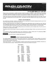
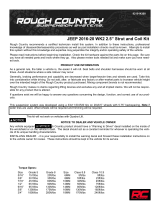
Kit Contents:
2– Front Strut Spacers (A)
2- Front Strut Coil Spring Spacers (B)
2– Dr/Pass Front Sway Bar Reloc bracket (C)
2- Rear Inner Lower Control Arms (D)
2- Rear Outer Lower Control Arms (E)
1– 10MMSTUDBAG-1
1--1665 Bag1 Containing:
2-Front Camber Bolts (F)
2-14mm x 60mm Cam Bolts (G)
4-Cam Washers (H)
2-14mm x 40mm Bolts
4-14mm Lock Nuts
4-14mm Flat Washers
2-Inner Control Arm Sleeves (I)
4-Inner Control Arm Bushings (J)
2-3/8”x 1 1/4” Bolt
2-3/8” Flange Lock Nuts
2-3/8” Flat Washers
2-8mm x 120mm Bolt
2-8mm Lock Nuts
4-8mm Flat Washers
A
A
B C
C
D D
E
G
G
H
H
I I
J
J
F

FRONT INSTALLATION INSTRUCTIONS
1. Chock the rear wheels and jack up the front of the vehicle and support the vehicle with jack stands so that the front wheels
are off the ground. Remove the tires/wheels.
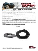
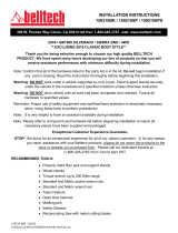
2. Remove the brake line from the strut using a 13mm socket. Retain stock hardware. See Photo 1.
3. Remove the ABS line from the knuckle. See Photo 2.
4. Remove the sway bar from the strut using a 15mm socket. Retain the stock hardware. See Photo 3.
5. Remove the lower strut bolts using a 21mm socket and wrench. See Photo 4.
Tools Needed:
Jack
Jack Stands
13mm Wrench/Socket
15mm Wrench/Socket
17mm Wrench/Socket
18mm Wrench/Socket
21mm Wrench/Socket
9/16” Wrench/Socket
Size Grade 5 Grade 8
5/16” 15 ft/lbs 20 ft/lbs
3/8” 30 ft/lbs 35 ft/lbs
7/16” 45 ft/lbs 60 ft/lbs
1/2” 65 ft/lbs 90 ft/lbs
9/16” 95 ft/lbs 130 ft/lbs
5/8” 135 ft/lbs 175 ft/lbs
3/4” 185 ft/lbs 280 ft/lbs
Class 8.8 Class 10.9
6MM 5 ft/lbs 9 ft/lbs
8MM 18ft/lbs 23 ft/lbs
10MM 32ft/lbs 45ft/lbs
12MM 55ft/lbs 75ft/lbs
14MM 85ft/lbs 120ft/lbs
16MM 130ft/lbs 165ft/lbs
18MM 170ft/lbs 240ft/lbs
Torque Specs:
Photo 1 Photo 2
Photo 3 Photo 4

6. Remove the upper strut nuts using a 15mm socket. See Photo 5.
7. Remove the strut from the vehicle.
8. Install the supplied studs in the front spacer using a 17mm socket. See Photo 6.
9. Compress the strut using a strut compressor and remove the upper nut using a 18mm socket. See Photo 7.
10. The stock upper retaining bushing will be reused from the upper strut hat. See Photo 8.
11. Install the coil spring spacer as shown with factory retaining bushing as shown in Photo 8.
12. Re-install the upper strut retainer with the factory hardware. See Photo 9. Tighten using a 18mm socket.
Photo 5 Photo 6
Photo 7
Photo 9 Photo 10
Photo 8

13. Install the strut spacer on the strut and tighten the factory nuts using a 15mm socket. See Photo 11.
14. Re-install the strut assembly in the upper strut mount with suppled nuts & washers. Do not tighten at this time.
15. Install the supplied camber bolt in the upper location as shown and stock hardware in the lower hole. Tighten upper camber
bolt using a 15mm & 18mm wrench. Factory lower using a 21mm socket and wrench. See Photo 12.
16. Tighten the upper strut hardware using a 17mm wrench.
17. Install the supplied sway bar link relocation bracket as shown with the supplied 3/8” x 1 1/4”bolts, flange lock nuts and 2
washers, with threads facing outward. Tighten using a 9/16” wrench. See Photo 13.
18. Install the factory sway bar link in the bracket with the factory nut. See Photo 14. Tighten using a 15mm wrench.
19. Reinstall the brake line on the knuckle using factory hardware and tighten using a 13mm wrench.
20. Reinstall the ABS wire on the knuckle in the factory location.
21. Reinstall the tires and wheels. Torque to factory specifications.
Photo 12
Photo 13 Photo 14
Photo 10

REAR INSTALLATION INSTRUCTIONS
1. Chock the front wheels and jack up the rear of the vehicle and support the vehicle with jack stands so that the rear wheels
are off the ground. Remove the tires/wheels.
2. Remove the brace as shown from both passenger and driver side using a 15mm wrench. See Photo 1.
3. Remove the sway bar link as shown using a 13mm wrench & socket. Retain bushings, cup washers and lower nut for reuse.
See Photo 2. The center link body will not be re-used.
4. Support the lower control arm with a floor jack under the outer mount of the control arm. See Photo 3.
5. Remove the outer arm hardware using a 18mm wrench from the hub assembly as shown in Photo 4. Retain the stock hard-
ware for reuse.
6. Remove the inner control arm hardware using a 18mm wrench. Lower the arm assembly using the floor jack. See Photo 5.
7. Remove the strut hardware from the lower arm using a 18mm wrench and remove the arm. See Photo 6.
Photo 1 Photo 2
Photo 3 Photo 4
Photo 5 Photo 6

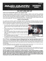
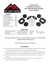
8. Assemble the bushings/sleeves in the lower inner arm and assemble with the lower outer arm with the supplied cam bolts,
washers and 14mm x 40mm bolts, washers and lock nuts. Do not tighten at this time. See Photo 7.
9. Install the new lower arm assemble on the strut as shown in Photo 8. Do not tighten at this time.
10. Insert the outer assembly in the hub assemble, secure with the factory hardware and tighten. See Photo 9.
11. Using a floor jack on the arm hub assembly and inner arm at the same time, jack up the arm into position, align holes using
pry bar and install using the factory hardware. See Photo 10. Do not tighten at this time.
12. Install the factory bushings, cup washers as shown with the supplied 8mm x 120mm bolts, flat washers and lock nuts. See
Photo 11. The stock center link body will not be re-used.
13. Reinstall the brace removed in Step 2 on the completed side. Tighten using a 13mm wrench. See Photo 12.
14. Proceed to opposite side and repeat installation steps.
15. When completed, lower the vehicle to the ground and tighten the inner arm bolts and strut bolts using a 18mm socket and
wrench.
16. Reinstall tires/wheels.
Photo 8
Photo 9 Photo 10
Photo 11 Photo 12
Photo 7
Cam Washers Install here

POST INSTALLATION
1. Check all fasteners for proper torque. Check to ensure there is adequate clearance between all rotating, mobile,
fixed and heated members. Check steering for interference and proper working order. Test brake system.
2. Perform steering sweep. Cycle the steering from full turn to full turn to check for clearance. Failure to perform in-
spections may result in component failure.
3. Using an certified alignment professional with experience in aligning lifted vehicles, get a 4-wheel alignment done to
factory specifications.
4. Readjust headlights to proper settings. MAINTENANCE INFORMATION
It is the ultimate buyers responsibility to have all bolts/nuts checked for tightness after the first 500 miles and then every
1000 miles. Wheel alignment steering system, suspension and driveline systems must be inspected
by a qualified professional mechanic at least every 3000 miles.
By purchasing any item sold by Rough Country, LLC, the buyer expressly warrants that he/she is in compliance with all applica-
ble , State, and Local laws and regulations regarding the purchase, ownership, and use of the item. It shall be the buyers re-
sponsibility to comply with all Federal, State and Local laws governing the sales of any items listed, illustrated
or sold. The buyer expressly agrees to indemnify and hold harmless Rough Country, LLC for all claims result-
ing directly or indirectly from the purchase, ownership, or use of the items.
/