Page is loading ...

11-18 JEEP WK2 2.5” LIFT KIT
Rough Country recommends a certified technician install this system. In addition to these instructions, professional
knowledge of disassemble/reassembly procedures as well as post installation checks must be known. Attempts to install
this system without this knowledge and expertise may jeopardize the integrity and/or operating safety of the vehicle.
Please read instructions before beginning installation. Check the kit hardware against the parts list on this page. Be sure
you have all needed parts and know where they go. Also please review tools needed list and make sure you have need-
ed tools.
PRODUCT USE INFORMATION
As a general rule, the taller a vehicle is, the easier it will roll. Seat belts and shoulder harnesses should be worn at all
times. Avoid situations where a side rollover may occur.
Generally, braking performance and capability are decreased when larger/heavier tires and wheels are used. Take this
into consideration while driving. Do not add, alter, or fabricate any factory or after-market parts to increase vehicle height
over the intended height of the Rough Country product purchased. Mixing component brands is not recommended.
Rough Country makes no claims regarding lifting devices and excludes any and all implied claims. We will not be re-
sponsible for any product that is altered.
If questions exist we will be happy to answer any questions concerning the design, function, and correct use of our prod-
ucts.
This suspension system was developed using a 33x11.50-R20 tire on 20x8.5” wheels with 5.75” backspacing. Note if
wider tires are used, offset wheels will be required and trimming will be required.
This kit will not work on vehicles with Quadra-Lift.
NOTICE TO DEALER AND VEHICLE OWNER
Any vehicle equipped with any Rough Country product should have a “Warning to Driver” decal installed on the inside of
the windshield or on the vehicle’s dash. The decal should act as a constant reminder for whoever is operating the vehi-
cle of its unique handling characteristics.
INSTALLING DEALER - it is your responsibility to install the warning decal and forward these installation instructions on
to the vehicle owner for review. These instructions should be kept in the vehicle for its service
921603000
Torque Specs:
Size Grade 5 Grade 8
5/16” 15 ft/lbs 20 ft/lbs
3/8” 30 ft/lbs 35 ft/lbs
7/16” 45 ft/lbs 60 ft/lbs
1/2” 65 ft/lbs 90 ft/lbs
9/16” 95 ft/lbs 130 ft/lbs
5/8” 135 ft/lbs 175 ft/lbs
3/4” 185 ft/lbs 280 ft/lbs
Class 8.8 Class 10.9
6MM 5 ft/lbs 9 ft/lbs
8MM 18ft/lbs 23 ft/lbs
10MM 32ft/lbs 45ft/lbs
12MM 55ft/lbs 75ft/lbs
14MM 85ft/lbs 120ft/lbs
16MM 130ft/lbs 165ft/lbs
18MM 170ft/lbs 240ft/lbs

60300 Kit Contents:
2-Front Upper Strut Spacers
2-Front Strut Pre Load Spacers
2-Rear Coil Spacers
2-Rear Shock Spacers
1-60300BAG
2-7/16” Large Dia Washers
2-7/16” x 2.5” Bolts
4-7/16” Washers
2-7/16” Nylock Nuts
4-10mm Flat Washers
4-10mm x 40mm Bolts
6-8mm Nylock Nuts
Tools Needed:
5/8” Wrench/Socket
8mm Wrench/Socket
8mm Allen
10mm Socket/Wrench
13mm Wrench/Socket
16mm Socket
18mm Wrench/Socket
19mm Wrench
21mm Wrench/Socket
22mm Deep Well Socket
24mm Wrench
32mm Socket
Jack
Jack Stands
Torque Wrench
Hammer
Strut Compressor

1. Jack up the front of the vehicle and support the vehicle with jack stands, so that the front wheels are off the ground.
Chock rear wheels.
2. Remove the front tires/wheels, using a 22mm deep well socket.
3. Using a 13mm socket, remove the front skid plate. Retain hardware.
4. Unplug the electric power steering.
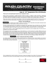
5. Using a 21mm wrench, loosen the tie rod end nut. Do not completely remove. See Photo 1.
6. Using a hammer, hit the knuckle at the tie rod end to release the taper. Remove and retain hardware for reuse. See
Photo 2.
7. Using a 19mm wrench and an 8mm socket, remove the sway link from the sway bar. Retain hardware for reuse.
See Photo 3.
8. Using a 21mm wrench, loosen the upper ball joint nut. Do not completely remove. See Photo 4.
9. Using a hammer hit the knuckle at the upper ball joint to release the taper. Remove the nut and retain for reuse.
See Photo 5.
10. Using a 10mm socket, remove the ABS sensor from the knuckle. Retain the hardware for reuse. See Photo 6.
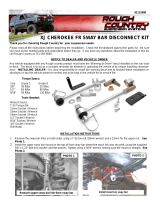
FRONT INSTALLATION INSTRUCTIONS
PHOTO 1 PHOTO 2
PHOTO 3 PHOTO 4
PHOTO 5 PHOTO 6
Loosen tie rod end nut.
Remove sway link. Loosen upper ball joint nut.
Remove ABS sensor.

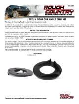
11. Using a 21mm socket, remove the brake caliper and hang caliper out of the way. Retain hardware for reuse. Do
not hang caliper by the brake line. See Photo 7.
12. Remove the rubber o-ring from the hub and remove the brake rotor. Retain o-ring for reuse. See Photo 8.
13. Using a 32mm socket, remove the axle nut. Retain nut for reuse. See Photo 9.
14. Using a 24mm wrench and an 8mm Allen, remove the lower ball joint nut. See Photo 10.
15. Remove the knuckle from the Jeep.
16. Using 21mm and 24mm wrenches, remove the lower strut hardware. Retain the hardware for reuse. See Photo 11.
17. Some models require removal of an electrical relay on the pass side. Remove the plastic cover and use a 10mm
socket to unbolt the assembly. Unclip the harness and move until upper strut nuts are accessible.
18. Using a 13mm socket, remove the upper strut hardware from under the hood. Retain hardware for reuse. See
Photo 12.
19. READ ENTIRE STEP: Slightly pull the axle out of the diff housing and rest on the lower control arm.
TAKE CARE TO NOT DAMAGE THE BOOT.
20. Remove the axle and strut together to prevent strut fork from damaging CV boot.
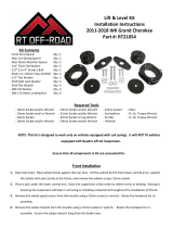
PHOTO 7 PHOTO 8
PHOTO 9 PHOTO 10
PHOTO 11 PHOTO 12
Remove brake caliper. Remove hub o-ring.
Remove axle nut. Remove lower ball joint nut.
Remove lower strut bolt. Remove upper strut nuts.

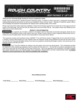
21. Install the supplied strut spacer on the strut using the supplied 8mm hardware. Tighten using a 13mm wrench. See
Photo 13.
22. Place the strut assembly into a strut compressor as shown in Photo 14. Mark the top-hat, top of the coil and the
isolator, then mark the bottom of the coil spring and the strut body as shown in Photo 14.
23. Carefully compress the strut and rotate the bottom of the strut 180°. See Photo 15.
24. Keeping the strut compressed, remove the top nut using an 18mm socket. Retain hardware.
25. Remove the strut hat and factory isolator. See Photos 16 & 17.
26. Install the supplied pre load spacer between the factory isolator and the strut hat. See Photo 18.
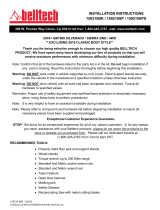
PHOTO 13 PHOTO 14
PHOTO 15
Mark top-hat, isolator, coil, and strut body.
Install upper strut spacer.
Rotate bottom of strut.
PHOTO 16
Remove strut hat and isolator.
PHOTO 17
Remove strut hat and isolator.
PHOTO 18
Install strut pre load spacer.

27. Install the strut hat assembly into the coil, making sure to align the marks made on the top-hat, top of the coil and
isolator in step 22. Make sure that the mark on the bottom of the coil is still 180° from the mark on
the strut body. See Photo 19.
28. Place the strut and coil assembly in the strut compressor, compress the strut, and install the factory top nut using an
18mm socket.
29. Install the strut assembly and axle on the vehicle using the factory hardware for the upper and lower mounts.
Torque to factory specs.
30. Install the knuckle on the lower ball joint and tighten using a 24mm wrench and an 8mm Allen.
31. Install the axle nut and torque to factory specs using a 32mm socket.
32. Install the brake rotor and o-ring.
33. Install the brake caliper using the factory hardware. Torque to factory specs using a 21mm socket.
34. Install the ABS sensor into the knuckle using a 10mm socket.
35. Install the upper ball joint into the knuckle and tighten using a 21mm wrench.
36. Install the sway link into the sway bar using the factory hardware. Tighten using a 19mm wrench and an 8mm
socket.
37. Install the tie rod end into the knuckle and tighten using a 21mm socket.
38. Repeat steps 5-37 on opposite side of the vehicle.
39. Connect the electric power steering plug.
40. Install the factory skid plate using the factory hardware, torque to factory specs using a 13mm socket.
41. Install the wheels and tires and lower the vehicle to the ground.
PHOTO 19
Install strut hat assembly w/ isolator.

Rear Installation
1. Using an 18mm wrench and socket, remove the tow bar from the knuckle. See Photo 1.
2. Using 18mm and 8mm wrenches, remove the sway link from the sway bar. Retain hardware. See Photo 2.
3. Using an 18mm wrench and socket, remove the 2 upper control arms from the knuckle. Retain hardware. See
Photo 3.
4. If applicable, remove the ride height sensor linkage using a 10mm wrench.
5. Using a 10mm socket, remove the ABS line from the brake caliper and hang out of the way.
6. Place a jack under the lower control arm to support it.
7. Using 21mm and 24mm wrenches, remove the lower shock hardware. Retain hardware. See Photo 4.
8. Mark the position of the coil spring in relation to the vehicle body and upper coil spring isolator.
9. Slowly lower the jack and remove the coil spring. See Photo 5.
10. Remove the lower coil isolator from the lower control arm by pushing in on the clips from the underside. Note the
position of the lower isolator in the lower control
arm as the new supplied spacer will be oriented
the same, in the following step.
PHOTO 1 PHOTO 2
PHOTO 3
Remove sway link.
Remove the toe link.
Remove upper control arms.
PHOTO 4
Remove lower shock hardware,.
PHOTO 5
Remove the coil spring.

11. Remove the push pins from the inner fender just behind the shock. See Photo 6.
12. Using a 16mm socket, remove the upper shock bolts. See Photo 7.
13. Install the supplied spacer on top of the shock and install in the upper mount using the supplied 10mm x 40mm
bolts and washers. Torque to 32ft/lbs using a 16mm socket. See Photo 8.
14. Install the supplied lower spacer in the lower control arm according to the noted position in step 11. See Photo 9.
15. Install the factory coil spring in the upper mount and on the lower spacer. See Photo 10.
16. Place the supplied 7/16” x 3.5” bolt, small washer and large dia. washer through the lower coil spacer from the
underside of the lower control arm. See Photo 11.
PHOTO 6 PHOTO 7
PHOTO 8
Remove the upper shock hardware.
Remove push pins from inner fender liner.
Install shock and upper spacer.
PHOTO9
Install lower coil spacer.
PHOTO 10
Install coil spring.
PHOTO 11
Install coil spacer bolt and washers.

17. Place the supplied 7/16” nylock and washer inside the coil spring and on the 7/16” bolt. See Photo 12.
18. Torque the 7/16” hardware to 60ft/lbs using a 5/8” wrench and socket. See Photo 13.
19. Install the shock on the lower control arm. Torque to factory specs using a 24mm wrench and 21mm socket. See
Photo 14.
20. Attach the sway link to the sway bar using the factory hardware. Tighten using 18mm and 8mm wrenches See
Photo 15.
21. Install the upper control arms using the factory hardware. Torque to factory specs using an 18mm wrench and
socket. See Photos 16 & 17.
PHOTO 12 PHOTO 13
PHOTO 14
Torque coil spacer hardware.
Install coil spacer hardware.
Install shock on lower control arm.
PHOTO 15
Attach sway link to sway bar.
PHOTO 16
Install upper control arms.
PHOTO 17
Install supper control arms.

22. Install the toe link using the factory hardware. See Photo 18.
23. Repeat process on opposite side of the vehicle.
24. Install the wheels and tires and lower the vehicle to the
ground. PHOTO 18
By purchasing any item sold by Rough Country, LLC, the buyer expressly warrants that he/she is in compliance with all
applicable , State, and Local laws and regulations regarding the purchase, ownership, and use of the item. It shall be
the buyers responsibility to comply with all Federal, State and Local laws governing the sales of any
items listed, illustrated or sold. The buyer expressly agrees to indemnify and hold harmless Rough
Country, LLC for all claims resulting directly or indirectly from the purchase, ownership, or use of the
items.
Install toe link.
POST INSTALLATION INSTRUCTIONS
1. Check all fasteners for proper torque. Check to ensure for adequate clearance between all rotating, mobile, fixed,
and heated members. Verify clearance between exhaust and brake lines, fuel lines, fuel tank, floor boards and wiring
harness. Check steering gear for clearance. Test and inspect brake system.
2. Perform steering sweep to ensure front brake hoses have adequate slack and do not contact any rotating, mobile or
heated members. Inspect rear brake hoses at full extension for adequate slack. Failure to perform hose check/ re-
placement may result in component failure.
3. On some vehicles the front lower skirting will need to be trimmed if using certain wheel /tire combinations and with
heavy offset wheels. Trim only as needed.
4. Activate four wheel drive system and check front hubs for engagement.
5. Have a qualified alignment center align the vehicle immediately. Realign to factory specifications. The following are
the recommended specifications:
Caster in degrees +6.95° +-.50°
Camber in degrees -.38° +-.50°
Toe In in degrees +0.1 +-.06°
6. Perform head light check and adjustment to proper settings.
7. Check and retighten wheels at 50 miles and again at 500 miles.
8. All kit components must be retightened at 500 miles and then every three thousand miles after installation. Periodi-
cally check all hardware for tightness.
9. Install “Warning to Driver” decal on sun visor
Note: Installation of larger tires will require speedometer recalibration.
Thank you for choosing Rough Country for all of your suspension needs.
/