Bauknecht DDT 7790 IN Program Chart
- Category
- Cooker hoods
- Type
- Program Chart

5019 418 33034
DDT 7790
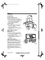
INSTALLATIONSANGABEN
Mindestabstand zur Kochfläche: 50 cm (Elektrokochplatten), 75 cm (Gas-, Öl- oder
Kohlekochplatten). Folgen Sie bei der Installation der Nummerierung (1Ö2Ö3Ö....).
Schließen Sie das Gerät erst nach erfolgter Installation an die Stromversorgung an.
Achtung! Das Auslassrohr und die Befestigungsmanschetten (15) sind nicht im
Lieferumfang inbegriffen und müssen gesondert erworben werden.
INSTALLATION SHEET
Minimum height above cooker: 50 cm (electric cookers), 75 cm (gas, gas oil or coal
cookers). To install, follow points (1Ö2Ö3Ö.....). Do not connect the appliance to the
electrical power supply until installation is completed. Warning! The exhaust pipe
and clamps (15) are not supplied and must be bought separately.
FICHE D’INSTALLATION
Distance minimale par rapport à la cuisinière : 50 cm (cuisinière électrique), 75 cm
(cuisinière à gaz, mazout ou charbon). Pour le montage, suivez la numérotation
(1Ö2Ö3Ö.....). Ne branchez pas l’appareil tant que l'installation n’est pas terminée.
Attention ! Le conduit d'évacuation et les colliers de fixation (15) ne sont pas
fournis et doivent être achetés à part.
INSTALLATIEKAART
Minimumafstand tot het kooktoestel: 50 cm (elektrische kooktoestellen), 75 cm
(kooktoestellen op gas, olie of kolen). Volg voor de montage de nummering
(1Ö2Ö3Ö.....). Geef het apparaat geen stroom totdat de installatie geheel voltooid
is. Let op de afvoerbuis en de klembanden (15) worden niet bijgeleverd en moeten
apart worden aangeschaft.
FICHA DE INSTALACIÓN
Distancia mínima desde los quemadores: 50 cm (quemadores eléctricos), 75 cm
(quemadores de gas, gasóleo o carbón). Para el montaje, siga la numeración
(1Ö2Ö3Ö...). No conecte el aparato a la corriente eléctrica hasta que la instalación
esté completamente finalizada. ¡Atención! El tubo de descarga y las abrazaderas
(15) no están incluidas y se compran aparte.
FICHA DE INSTALAÇÃO
Distância mínima dos fogões: 50 cm (fogões eléctricos), 75 cm (fogões a gás,
gasóleo ou carbono). Para a montagem siga a numeração (1Ö2Ö3Ö.....). Não ligue o
aparelho à corrente eléctrica até a instalação estar concluída. Atenção! O tubo de
descarga e as tiras de fixação (15) não são fornecidas e devem ser compradas à parte.
SCHEDA INSTALLAZIONE
Distanza minima dai fuochi: 50 cm (fuochi elettrici), 75 cm (fuochi a gas, gasolio o
carbone). Per il montaggio seguire la numerazione (1Ö2Ö3Ö.....). Non dare corrente
all’apparecchio finché l’installazione non è totalmente completata. Attenzione! Il
tubo di scarico e le fascette di fissaggio (15) non sono fornite e vanno acquistate a
parte.
ȀǹȇȉǼȁǹ ǼīȀǹȉǹȈȉǹȈǾȈ
ǼȜȐȤȚıIJȘ ĮʌȩıIJĮıȘ Įʌȩ IJȚȢ İıIJȓİȢ: 50 cm (ȘȜİțIJȡȚțȑȢ İıIJȓİȢ), 70 cm (İıIJȓİȢ ĮİȡȓȠȣ,
ʌİIJȡİȜĮȓȠȣȒ µİ țȐȡȕȠȣȞȠ). īȚĮ IJȘȞ IJȠʌȠșȑIJȘıȘ ĮțȠȜȠȣșȒıIJİ IJȘȞ ĮȡȓșµȘıȘ (1Ö2Ö3Ö.....).
ȂȘȞ IJȡȠijȠįȠIJİȓIJİ µİ ȘȜİțIJȡȚțȩ ȡİȪµĮ IJȘ ıȣıțİȣȒ ʌȡȚȞ IJȘȞ ȠȜȠțȜȒȡȦıȘ IJȘȢ
İȖțĮIJȐıIJĮıȘȢ. ȆȡȠıȠȤȒ! ȅ ıȦȜȒȞĮȢ ĮʌĮȖȦȖȒȢ țĮȚ IJĮ țȠȜȐȡĮ ıIJİȡȑȦıȘȢ (15) įİȞ
įȚĮIJȓșİȞIJĮȚ țĮȚ ʌȡȑʌİȚ ȞĮ ĮʌȠțIJȘșȠȪȞ ȤȦȡȚıIJȐ.
D
GB
F
NL
E
P
I
GR
41833034.fm Page 1 Monday, November 3, 2003 11:58 AM

5019 418 33034
DDT 7790
=
=
X
G
17b
17b
4-13
4-13
1
2
3
11
11
12
15
17a
17a
6
5
16
B
G
H
8
8
18
F
9
10
14
7
9
1
0
1
4
7
5
6
4 x 4x8
4 x 3,5x9,5
2 x
2,9x6,5
41833034.fm Page 2 Monday, November 3, 2003 11:58 AM

5019 418 33034
DDT 7790
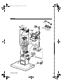
Preliminary information for installing the hood:
Disconnect the power supply at the domestic main switch before carrying out electrical
connections.
Remove the grease filter/s.
Pre-assemble the three parts of the flue support bracket with 4 screws. The width X of the
bracket G must be identical to the internal width of the telescopic flue.
1. Using a pencil, draw the centre line on the wall up to the ceiling to facilitate installation
operations.
2. Attach the hole diagram to the wall: the vertical centre line printed on the hole diagram
must match the centre line drawn on the wall, and the lower edge of the hole diagram must
match the lower edge of the hood: remember that with installation completed the bottom
of the hood must be at least 50 cm above the cooktop in case of electric cookers and 75 cm
in case of gas or mixed cookers.
3. Place the support bracket on the hole diagram so that it matches the dashed rectangle, mark
the two external holes and drill, remove the hole diagram, insert 2 wall plugs and fix the
hood support bracket with two 5x45 mm screws.
4. Hook the hood to the bracket.
5. Adjust the distance between the hood and the wall.
6. Adjust the hood horizontally.
7. From the inside of the extraction unit, mark the holes for fixing the hood.
8. Remove the hood from the bracket.
9. Drill on the mark (Ø 8 mm - see step 10).
10.Insert 2 wall plugs.
11.Fit the flue support bracket G to the wall and against the ceiling, use the support bracket as
hole diagram (the small slot on the support must match the line drawn on the wall - step 4)
and mark 2 holes with the pencil, drill the holes (Ø 8 mm), and finally insert 2 plugs.
12.Fix the flue support bracket to the wall with two 5x45 mm screws.
13.Hook the hood to the bottom bracket.
14.Fix the hood to the wall with two 5x45 mm screws (ABSOLUTELY NECESSARY).
15.Connect an exhaust pipe (pipe and clamps are not supplied and must be bought separately)
to the collar B located above the extraction motor unit.
For extractor operation, connect the other end of the exhaust pipe to the home discharge
device. For filter operation, fix the deflector F to the flue support bracket G and connect the
other end of the exhaust pipe to the deflector collar F. Once the steam and fumes have been
filtered by the carbon filter (not provided, to be ordered separately) they are conveyed back
to the kitchen through grid H.
16.Carry out the electrical connection.
17.Apply the flues and fix them with 2 screws (20a) to the flue support G (20b).
18.Slide the bottom section of the flue in the special seat above the hood to completely cover
the extraction unit.
Refit the grease filter/s and check for correct hood operation.
INSTALLATION - ASSEMBLY INSTRUCTIONS
D F NL EGB
P I GR
41833034.fm Page 6 Monday, November 3, 2003 11:58 AM

5019 418 33034
DDT 7790
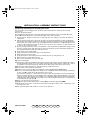
CONTROL PANEL
Control panel calibration
When the appliance is plugged in (or after a power failure) the system calibrates the buttons;
during calibration two blinking dots will appear.
The calibration lasts for 15''.
At the end of the calibration procedure, the two dots will stop blinking and only the bottom
right dot will stay alight.
1. ON button (Stand by) / OFF extraction / Resetfilter saturation indicator:
- ON (Stand by) - the display shows a lighted dot only.
- OFF - the display is OFF: all controls, except for the light button, are disabled.
To set the hood to ON (Stand by) or OFF, press the button and wait until the dot appears or
disappears according to the required setting.
Reset filter saturation indicator. Press and hold for at least 3 seconds, an acoustic signal
will sound. The reset operation can only take place when the hood is on.
2. Light ON/OFF button.
3. Extraction speed decrease button (1, 2, 3, P-intensive).
4. Extraction speed increase button (P-intensive, 3, 2, 1).
Warning! The intensive extraction speed appears on the left of the display with the letter P and
the remaining operating time in minutes (and the blinking dot) on the right; after 5 minutes, it
automatically switches to extraction speed 2.
5. Timer button: after selecting the required extraction speed, press this button to set the
timing:
Extraction speed 1: 20 minutes
Extraction speed 2: 15 minutes
Extraction speed 3: 10 minutes
Intensive extraction speed (P): 5 minutes
The display will show the remaining operating time and the blinking dot on the right.
At the end, the hood will switch off.
Press again to disable the timing.
6. Display: shows the selected extraction speed, grease filter (F) or carbon filter (C)
saturation, Stand by mode (lighted dot) and control panel calibration (two blinking
dots).
Warning! The carbon filter saturation indicator is normally deactivated (for extractor
version - see attached instructions manual). In order to activate it (for filter operation - see
attached instructions manual), simultaneously press AND HOLD buttons 3 and 4 until C appears
on the display. To deactivate the carbon filter saturation indicator, simultaneously press AND
HOLD buttons 3 and 4: letter F will appear on the display, followed by C. The latter will
disappear after a few seconds.
12345
6
FIG. 1
PRODUCT SHEET
D F NL EGB
P I GR
41833034.fm Page 7 Monday, November 3, 2003 11:58 AM

5019 418 33034
DDT 7790
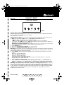
1. Control panel.
2. Grease filter.
3. Halogen bulbs.
4. Steam deflector.
5. Telescopic flue.
To clean the grease filter
Wash the grease filter at least once a month.
1. Disconnect the electrical power supply.
2. Remove the grease filters - Fig. 2: push the
spring release handle backwards (f1), then
remove the filter downwards (f2).
3. After cleaning the grease filter, remount in
reverse order ensuring the entire
extraction surface is covered.
Replacing bulbs
1. Disconnect the electrical power supply.
2. Use a small screwdriver or any other
suitable tool to prise off (m-Fig. 2) the
lamp cover (p-Fig. 2).
3. Remove the burnt-out bulb.
Replace using 20 W max halogen bulbs
only, making sure not to touch them with
your hands.
4. Close the lighting unit (snap-close).
Carbon filter Fitting and
Maintenance
Fitting the carbon filter:
1. Disconnect the electrical power supply.
2. Remove the grease filter (f1/f2 - Fig. 2).
3. Turn the side knobs 90° and then remove
the filter holder (g - Fig. 3).
4. Fit the carbon filter (h - Fig. 3) in the filter
holder (i - Fig. 3).
5. Refit the filter holder and secure it to the
hood by turning the side knobs 90°
(g - Fig. 3).
6. Refit the grease filter.
Carbon filter maintenance:
Unlike traditional carbon filters, this carbon
filter can be washed and reactivated.
With normal hood use, the filter should be
cleaned once a month. The best way to clean
the filter is in a dishwasher at the highest
temperature possible, using a normal
dishwasher detergent. To avoid particles of
food or dirt settling on the filter during
washing and giving rise to unpleasant smells,
it is advisable to wash the filter on its own.
After washing, dry the filter in the oven at
100°C for 10 minutes to reactivate it.
The filter will retain its odour-absorbing
capacity for three years, after which it must be
replaced.
4
2
f1
f2
3
5
1
m
p
FIG. 3
FIG. 2
D F NL EGB
P I GR
41833034.fm Page 8 Monday, November 3, 2003 11:58 AM
-
 1
1
-
 2
2
-
 3
3
-
 4
4
-
 5
5


Bauknecht DDT 7790 IN Program Chart
- Category
- Cooker hoods
- Type
- Program Chart
Ask a question and I''ll find the answer in the document
Finding information in a document is now easier with AI
Related papers
-
Bauknecht DKEL 5790 IN Program Chart
-
Bauknecht DTR 5890/IN/01 Program Chart
-
Bauknecht DKLC 3710 IN Program Chart
-
-
Whirlpool DDB 5390 AL User guide
-
Bauknecht DDLE 5790 IN Program Chart
-
Whirlpool DNHV 5363 SG User guide
-
-
-
Bauknecht DBR 6990/IN Program Chart
Other documents
-
Whirlpool AKR 950 IX WP Program Chart
-
-
-
Whirlpool AKR 921 AL Program Chart
-
Whirlpool AKR 957 IX WP Program Chart
-
-
-
Maytag MET 9050 PAS Program Chart
-
Whirlpool AKR 651 WH Program Chart
-
IKEA HOO 600 S Program Chart