HySecurity SwingRiser – HRG Relay Owner's manual
- Category
- Gate Opener
- Type
- Owner's manual

www.hysecurity.com
D0779
SwingRiser - HRG
Relay manual
DISCLAIMER
HySecurity relay-controlled hydraulic gate operators
do not meet current UL 325 Safety Standards and that
HySecurity recommends decommission and
replacement of all manufacturers’ relay-controlled
operators with modern Smart Touch™ based
operators, which fully comply with UL 325 safety
standards. By downloading and using this document
you acknowledge that HySecurity no longer provides
parts or technical support for those older operators.
Note
HySecurity accepts no responsibility, implied or
express, for claims arising from continued use of pre-
2001 relay-controlled operators.

HR30
Hy-Security Gate Operators
HRG 220 SWING GATE OPERATOR, SINGLE
HRG 222 SWING GATE OPERATOR, PAIR
HANDBOOK
Manufacturers and Designers of Hydraulic Systems

OBSOLETE

OBSOLETE

OBSOLETE

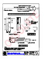
3
2
1
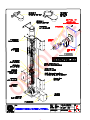
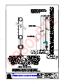
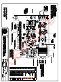
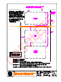
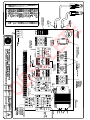
NOTE: ALL LATERAL FORCES MUST BE SUPPORTED BY BACKING POST/PILASTER.
SINGLE POST SHOWN. OPPOSITE POST SIMILAR MIRROR IMAGE.
CUSTOM DIMENSIONS MUST BE APPROVED BY FACTORY BEFORE ORDER IS ACCEPTED.
CUSTOM HEIGHT ADDS TO THIS DIMENSION.
seattle, washington
TITLE
DRAWING NUMBER:
1 1
SHT OF
HR34
REVDRAWN
APPROVED
CHECKED
DATE
DATE
DATE
6/23/00KERI
PART NUMBER
N/A A
91
2"7"
8"
16 1
2"
3"
3"
7"
12"
9"
11
2"
111
2"
9"
14 1
2"
12"
81"
57"
10"
5"
9"
12
3
8"
60"
8"
CUSTOM HEIGHT
"
LOCATION OF
OPTIONAL 2nd
INDEX ARM
"
"
CUSTOM HEIGHT
INDEX ARM BRACKET
3" X 3"
HINGE
BEARING
ACCESS
PANEL
LIMIT SWITCH
ACCESS PANEL
STANDARD
INDEX ARM
BRACKET
HOSE ACCESS PANEL
TYPICAL TOP CAP INSTALLATIONS
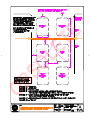
FOOTPRINT DIMENSIONS
6" PIPE BRACKET
4" PIPE BRACKET PILASTER BRACKET
5/8" SQUARE
ENGRNG REL NOTICE
ERN000043
3/4" BOLT HOLES
(2 PLACES)
3/4" MOUNTING
SLOTS (4 PLACES)
BASE PLATE
CUSTOM REQUEST STANDARD DIMENSIONS
12
3
6" X 6" PLATE
CUTOUT
13"
OBSOLETE

OBSOLETE

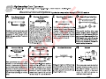
Operator MaintenanceOperator Maintenance
Operator MaintenanceOperator Maintenance
Operator Maintenance
Hydraulic System
Fluid Level: Under normal conditions, hydraulic systems do not consume oil. Before adding any oil, check the
system thoroughly for leaks. Remove the bright metal plug in the tank, fill to plug level, then replace plug. We
recommend our Uniflow hydraulic oil, part number H-004, which is sold in one gallon containers by our distribu-
tors. Automatic transmission fluid may be used, although its performance in cold weather will be sluggish unless
the operator is well heated. Do not use brake fluid.
Look for leaks: Occasionally there may be slight seeping at the fittings after some usage. Tightening of the fittings
will usually correct the problem. If the leaking persists, replace "O" rings, fittings or hoses, if required. No further
leaks should occur.
Oil Change: A hydraulic system does not foul its oil, unlike a gas engine, so oil changes do not need to be frequent.
Rather, heat breakdown is the main concern in a hydraulic system. If the unit is subjected to high use, especially in
a warm climate, change the oil more frequently. In general, we recommend draining the reservoir and replacing the
oil at five or ten year intervals.
There are several ways to change the hydraulic oil, depending on the type of operator being serviced. If you
don’t know how to drain the oil, contact your distributor for directions. Refill with new Uniflow hydraulic oil
(available from your distributor). To avoid overfilling, never pour into the port where the black breather cap is
located. Instead, remove only the bright metal plug in the tank. Slowly pour the oil into the tank until the oil is
within one inch of the filler port. Replace the plug and wipe up any spilled oil.
Cold Weather:
1. Check that your reservoir is filled with Uniflow high performance oil.
2. Ice can partly or totally jam gate operation. Check by operating the gate manually.
Electrical Controls
Before servicing, turn off power disconnect switch
No routine maintenance is needed for the electrical system or controls. If the environment is very sandy or dusty, seal
all holes in the electrical enclosure. Blow dust out of the electric panel with compressed air. A qualified electrician may
troubleshoot with the aid of the electrical drawings in Appendix 4.
If it is necessary to call a distributor for assistance, be sure to have your model and serial number ready. Other helpful
information would include the name of the job, approximate date of installation, and the service record of the operator,
especially any work that has been done recently. Be prepared to describe as exactly as you can what the machine is or
is not doing. Describe any unusual sounds or location of oil leaks.
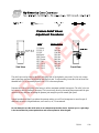
How to Adjust the Pressure Relief Valve: To check your relief valve setting, first disconnect one of the hoses.
Run the operator either open or closed (the gate will not move with the hose disconnected. The relief valve is found
on the rear of the hydraulic power unit. It has a hex adjusting head and lock nut. To adjust, loosen the lock nut and
screw the threaded bolt clockwise for increased pressure, counterclockwise to decrease pressure.
MODEL FACTORY SETTING
111 Series 750 psi
SS, E Models 1000 psi
EX Model 1300 psi
444 Series 1300 psi
Do not attempt to use the relief valve as an entrapment protection device. Photocells or gate edges are the best
methods to protect pedestrians and reserve power to the drive gate.
5/25/00 G39
OBSOLETE

OBSOLETE

OBSOLETE

OBSOLETE

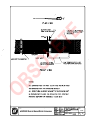
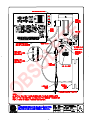
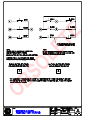
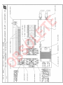
Field Hose Measurements for
HVG and HRG Operators
When field measuring for the necessary hose length to order, the following may be helpful:
There is little room in the base of the HRG or the HVG operators and limited room in the
control/power panel, therefore, your field measurements must be very accurate when
calculating the length of the necessary hydraulic hoses. If your dimensions are too little, you
will not reach the connections, if your measurements are too long, you will have trouble
finding space for the excess hose.
Remember that two hoses are needed for each motor or each cylinder. This means that you
need four hoses when you are dealing with a HVG operator and also when you are installing a
HRG 222 (pair) operator.
#3
#4
#2
#5
#1
Roadway
Be sure to measure accurately the following distances: (the best way is to pull a cord through
the conduit, mark it, and then measure it.)
1. The bottom of the pump/control panel to the bottom of the trench.
2. The total distance across the trench.
3. The distance back up to the bottom of the operator.
4. Add approximately 6" for the hoses to reach up into the operator.
5. Add approximately 24" for the hoses to reach up into the power/control panel.
The part numbers for the hoses are:
1/4" hose for HRG: H SFHO 004 SW
3/8" hose for HVG: H SFHO 006 4216
For assistance call your distributor.
#2
(if necessary)
2 ea. hydraulic hoses
in 2" conduit
3/4" conduit for electrical
only
5/11/00 HV/HR45
OBSOLETE

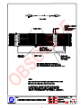
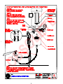
INSTALLATION INSTRUCTIONS FOR HRG SWING GATE OPERATORINSTALLATION INSTRUCTIONS FOR HRG SWING GATE OPERATOR
INSTALLATION INSTRUCTIONS FOR HRG SWING GATE OPERATORINSTALLATION INSTRUCTIONS FOR HRG SWING GATE OPERATOR
INSTALLATION INSTRUCTIONS FOR HRG SWING GATE OPERATOR
1. Permanent Wiring Shall Be Employed. Run wire in conduit and wirenut to the loose wires that are connected
to the disconnect switch. The disconnect switch is located on the baffle surrounding the electric control panel.
Note 1: Proper grounding is required and grounding wire is located in the disconnect switch area.
Note 2: Before servicing or opening electrical panel, be certain to turn off all electric power.
2. Button Station Operation: Install the push button control station within sight of the gate. Be sure gate opening
is clear before operating gate. Connect the push button to the terminal strip as detailed on drawing E57. If the
distance is greater than 200 feet, see E71 for details on long range pushbutton control.
3. Entrapment Protection - minimum safeguards:
A. Since automatic gates are not intended for pedestrian use, always install a separate pedes-
trian walkway and access gate. Install signs which direct persons to use the pedestrian gate,
and to not enter through the vehicle gate.
B. Be certain that all operating switches are located at least a six foot distance from the gate,
to reduce the possibility of any attempt to reach through in order to operate the gate.
C. Be certain to mount at least two of the enclosed 8-1/2" x 11" warning placards on each side
of the gate to warn users of the hazards of a power operated gate.
D. Automatic Operation: Entrapment protection sensors must be installed to guard both the opening and
closing of the gate. Install two photo electric eyes, or attach a minimum of two edge sensors to create a
reversing function for each direction of gate travel. All sensors guarding the closing direction connect to
terminals #1 and #6 in the control box. All sensors guarding the opening direction connect to terminal #9
and #6. See drawing E41 for mounting and connection details of the edge sensors.
Caution: Vehicle detectors are not entrapment protection sensors.
4. Using 5/8"-3/4" anchor bolts, mount operator base with proper clearance from square tube to backing post. See
drawing HR34 for dimensions. It is important that the finished installation be plumb and true. Use shims if
necessary to level the operator base.
5. Attach the top of the operator to the backing post or supporting wall, using the bracket provided. The attaching
bracket "sleeves" inside the top of the operator post. Note: The backing post/column, (provided by others) must
accomodate all of the "tip over" loads imposed by the gate panel.
6. Mount the controller box near the gate operator. See drawing G39.
7. Pull six wires minimum (eight wires if close position indication is required) from control panel to junction area
in the base of the operator post assembly. This may be either by underground conduit or by a seal-tight conduit
mounted into the side of the base.
8. HRG operators normally do not ship with the hydraulic hoses included, until the exact length is specified by
the installer. See HV/HR45 and verify correct length has been ordered.
9. Pull the hoses in a 2" minimum conduit and connect, being certain to match the color coded ends. Also be certain
that the connectors are firmly snapped together.
10. Remove the lowest cover plate to expose the limit switches and connect the limit switch wiring according to
the tagged terminal numbers on the prewired cords. See HRG Electrical Connection Diagrams for more
information.
page 1 of 2 6/13/00 HR21b
OBSOLETE

11. Remove the shipping plug on the pump manifold and replace with the vented cap that is provided.
12. Connect appropriate power wiring to match voltage and phase of the operator. Be certain to oversize feeder
wires to allow for voltage drop (see wire size schedule, E16a & E16b), especially for single phase machines.
Machines to operate on high voltages (above 120 VAC) do not need a neutral wire. Wirenut the power feeders
to the loose wires at the back of the On/Off switch.
13. Verify that the primary tap of the control transformer is connected to match the supplied voltage.
It is especially important to distinguish between 208 and 230 volt supplies. The various voltage taps are identified
by a label on the transformer or in the electrical drawings.
14. Test basic functions of the operator first, before connecting any external control wiring. If your operator is
equipped with vehicle detectors, be certain that they are connected to a loop or unplugged so that they do not cause
interference with the function of the machine. If the motor turns, but nothing moves, reverse two poles of a three
phase power source. Also check that the by-pass valve is closed. Push in the round black knob that is located on
the right side of the pump manifold. Also be certain that the hose quick connectors are firmly engaged.
15. After testing the basic functions, follow our electrical connection diagrams to add any accessories or external
control wiring. Test the operator functions again.
16. Check the "soft stop" open timer, which is mounted on top of the control relay. The label on the timer dial
shows the minimum and maximum settings. In operation the timer only needs to be set long enough for the
gate to coast to a smooth stop after opening. There is no bad effect if the timer is set for too long, except that
the operator cannot be started closed until this timer times out.
Additional instructions, gate tensioner and lock pin assembly
1. Install the gate using the clamps provided and adjust for the correct clearance between the gate and the road
surface. Allow three inches clearance at the far end of the gate panel. See drawings for gate panel clearance
dimensions.
2. Clamp the index arm mounting bracket near the bottom of a vertical member of the gate. The best attachment
point is at the one-third to one-half of the gate length from the gate hinge.
3. Cut the index arm arm to the correct length. Connect the threaded rod end to the mounting bracket on the gate
panel. Drill a ½” hole and bolt the other end of the index arm to the mounting bracket on the operator post assembly.
4. Mount the locking pin mechanism on the lower corner of the free end of the gate panel in such a position that
the pin penetrates 2" into a lock receptacle when the gate is fully closed.
5. Bury a tube in the roadway to act as a receptacle for the locking pin. The tube should have an angular cut on
the tip and project about two inches above the grade to act as a "catch" for the locking pin. Use a 3-1/2" x 1-1/2"
tube of appropriate length for this purpose. Use blacktop or grout to create a mound around the exposed tube, so
passing vehicles encounter a smooth bump.
NOTICE: If the locking pin mechanism is not used, security of this system is adversely affected and the operator
drive shaft may be exposed to high stresses by wind loading or vandals. If the lock pin receptacle is not built or
installed to create a strike stop for the gate, the lock pin may not always align with the receptacle.
6. Adjust the threaded end of the index arm rod to place the far end of the gate in an exact position for the locking
pin to strike and slide down into the receptacle as the gate closes. The most reliable index arm adjustment will allow
the gate to swing slightly past center so that the lock pin firmly strikes the back of the receptacle and is held firmly
in that position. Tighten all parts of the index arm assembly firmly for trouble free operation.
page 2 of 2 6/13/00 HR21b
OBSOLETE

ADJUSTMENT OF FLOW CONTROL REGULATING VALVESADJUSTMENT OF FLOW CONTROL REGULATING VALVES
ADJUSTMENT OF FLOW CONTROL REGULATING VALVESADJUSTMENT OF FLOW CONTROL REGULATING VALVES
ADJUSTMENT OF FLOW CONTROL REGULATING VALVES
ON SWING GATE OPERATORSON SWING GATE OPERATORS
ON SWING GATE OPERATORSON SWING GATE OPERATORS
ON SWING GATE OPERATORS
HRG 220 swing gate operators have at least two flow control regulating valves. The flow control valve(s) need
to be adjusted correctly for proper performance of the gate operator. The flow control valve is the small square
brass valve device with the knurled adjusting knob, located just above the quick-disconnect fitting to the hydraulic
hoses. The most important flow control adjustment is the one governing the closing of the gate. The closing
flow control is the valve just above the quick-disconnect fitting that is painted red. Because the gate drops as is
closes, gravity could over-accelerate the gate, depending on it's weight. The job of the flow control valve is to
regulate the closing speed by preventing over-acceleration in the close cycle. The flow control is not intended to
be used as a true speed adjusting control valve because it would create a tremendous inefficiency if over-
tightened.
To Adjust the close flow control valve correctly, start with the valve fully open, (all color bands exposed) and
turn clockwise until you have achieved proper gate control in the closed direction. Because of the low flow rate
of the HRG operator, correct adjustment will be at the bottom third of the color bands on the flow control valve.
The most crucial part of the closing of the swing gate is when the lock pin strikes it's receptacle. The flow
control valve adjustment is most helpful for maintaining control at this point of operation. (Other important
adjustments are available for correct locking. See separate instructions on "Adjustment of Indexing Arm")
Adjustment of the flow control valve affecting the opening, is much less important. Set the valve at approximately
3 turns from fully closed, or in a position that creates the smoothest operation.
The HRG 222 pair of swing gates will have two flow control valves for the close direction and two for the open
direction. The close flow control valves adjust the same as single HRG operators except that the valve governing
the master post (post with the limit switch) must be set to cause the master gate post to operate slightly slower
than the slave gate post. Because there is only one limit switch for two gate posts, it is important that the slave
post reach the fully closed position before the master post. The master post will shut down power to both posts
when it reaches the fully closed position. The flow control valves for the open direction are adjusted only to
slightly slow the master opening speed to assure the same delay in limit function. The only other use for the flow
control valves is to help prevent the force of wind gusts from over-accelerating the gate.
Caution: Over-tightening of the flow control valves will cause the operator to draw more motor horsepower
than necessary or desirable.
Be certain to tighten the set screws on the adjusting knobs to lock your adjustments.
6/9/00 HR46
OBSOLETE

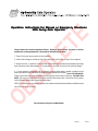
The procedure for manual operation follows. During a power failure, accident or serious
malfunction of the equipment, it is important to follow this procedure.
1. Turn off electrical power switch to the controller.
2. Unlock the locking pin (at the far end of the gate panel) and lift the pin out of it's receptacle.
3. Remove the bolt , or padlock, from the index arm mount on the operator post assembly and swing
away the entire index arm assembly. The gate panel is now free to swing on its auxiliary hinges.
4. If your operator is equipped with an optional accessory hand pump, manual operation can be
achieved from the control enclosure without using any mechanical releases. TO CLOSE THE GATE:
Simply operate the hand pump, located in the lower portion of the control enclosure. TO OPEN THE
GATE: pull and twist the knurled knob on the solenoid directional valve, (below the electric motor
on the hydraulic pump) then operate the hand pump.
NOTE: To return the valve to normal operation, be certain to release the knurled knob on the directional
valve by twisting it clockwise.
For assistance call your local Distributor.
Operation Instructions for Manual or Emergency SituationsOperation Instructions for Manual or Emergency Situations
Operation Instructions for Manual or Emergency SituationsOperation Instructions for Manual or Emergency Situations
Operation Instructions for Manual or Emergency Situations
HRG Swing Gate OperatorHRG Swing Gate Operator
HRG Swing Gate OperatorHRG Swing Gate Operator
HRG Swing Gate Operator
5/10/00 HR23
OBSOLETE

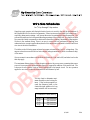
Pushbutton Control Wiring
16 ga 125' Maximum
14 ga 200' Maximum
12 ga 300' Maximum
10 ga 500' Maximum
Wire Size SchedulesWire Size Schedules
Wire Size SchedulesWire Size Schedules
Wire Size Schedules
for 1/2-hp through 5-hp motors
Supplying a gate operator with the right electrical service is crucial to the way the performance of
the operator the life of its electrical components. If the wire size used is too small, the voltage loss—
especially during motor starting—will prevent the motor from attaining its rated horsepower. The
percent of horsepower lost is far greater than the percentage of the voltage loss. A voltage loss could
also cause the control components to chatter while the motor is starting, substantially reducing their
life due to the resultant arcing. There is no way to restore the lost performance resulting from
undersized wires, except to replace them; therefore it is much more economical to choose a sufficient
wire size at the initial installation.
The tables on the following page are based on copper wire and allow for a 5% voltage drop. The
ampere values shown are the service factor ampere rating (maximum full load at continuous duty)
of the motor.
Always connect in accordance with the National Electrical Code, article 430, and other local codes
that may apply.
The maximum distance shown is from the gate operator to the power source; assuming that source
power is from a panel box with adequate capacity to support the addition of this motor load. The
values are for one operator, with no other loads applied to the branch circuit. For two operators
applied to one circuit, reduce the maximum allowed distance by half.
Use this chart to determine maxi-
mum allowable control wiring dis-
tance. If the location required ex-
ceeds the distances listed on the
chart at the right, addition of a long
range interface will be neccessary.
4/14/00 E16a
OBSOLETE

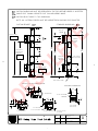
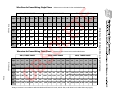
Wire Size for Voltage Drop Over Distance
E16b
Wire Sizes for Power Wiring, Single Phase Distances are shown in the unshaded boxes
Wire Gauge Wire Gauge
Always connect in accordance with the National Electrical Code, article 430, and other local codes that may apply.
Wire sizes for Power Wiring, Three Phase Distances are shown in the unshaded boxes
115 V, SINGLE PHASE 208 V, SINGLE PHASE 230 V, SINGLE PHASE
Amps 10.0 11.06 14.4 27.2 NA NA 5.5 6.1 7.6 14.2 16.2 NA 5.0 5.8 7.2 13.6 14.8 27.0
Horse 1/2hp 3/4hp 1hp 2hp 3hp 5hp 1/2hp 3/4hp 1hp 2hp 3hp 5hp 1/2hp 3/4hp 1hp 2hp 3hp 5hp
Power
12ga 90 75 60 30 290 260 205 110 100 350 300 245 130 120 65
10ga 140 120 100 50 460 415 330 175 155 560 480 385 205 190 105
8ga 220 190 155 80 725 650 525 280 245 880 760 610 325 300 165
6ga 350 300 245 130 1,150 1,040 835 445 390 1,400 1,120 975 515 475 260
4ga 555 480 385 205 1,825 1,645 1,320 710 620 2,220 1,915 1,550 815 750 410
2ga 890 765 620 330 2,920 2,630 2,110 1,130 1,000 3,550 3,060 2,465 1,305 1,200 660
208 V, THREE PHASE 230 V, THREE PHASE 460 V, THREE PHASE
Amps 2.7 3.1 4.2 6.5 6.7 16 2.4 3.0 3.8 6.2 6.4 15.4 1.2 1.5 1.9 3.1 3.2 7.7
Horse 1/2hp 3/4hp 1hp 2hp 3hp 5hp 1/2hp 3/4hp 1hp 2hp 3hp 5hp 1/2hp 3/4hp 1hp 2hp 3hp 5hp
Power
12ga 590 510 375 245 235 100 730 585 460 280 270 115 2,915 2,350 1,850 1,130 1,100 455
10ga 930 810 600 390 375 160 1,160 930 730 450 435 180 4,640 3,710 2,930 1,800 1,740 725
8ga 1,475 1,285 950 615 595 250 1,835 1,470 1,160 710 690 285 7,340 5,870 4,650 2,840 2,750 1,150
6ga 2,350 2,045 1,510 975 945 400 2,925 2,340 1,845 1,130 1,095 455 11,700 9,350 7,400 4,550 4,400 1,800
4ga 3,720 3,240 2,390 1,545 1,500 630 4,625 3,700 2,920 1,790 1,735 720 18,500 14,800 11,700 7,200 7,000 2,900
OBSOLETE

OBSOLETE

OBSOLETE
Page is loading ...
Page is loading ...
Page is loading ...
Page is loading ...
Page is loading ...
Page is loading ...
Page is loading ...
Page is loading ...
Page is loading ...
Page is loading ...
Page is loading ...
Page is loading ...
Page is loading ...
Page is loading ...
Page is loading ...
Page is loading ...
Page is loading ...
Page is loading ...
Page is loading ...
-
 1
1
-
 2
2
-
 3
3
-
 4
4
-
 5
5
-
 6
6
-
 7
7
-
 8
8
-
 9
9
-
 10
10
-
 11
11
-
 12
12
-
 13
13
-
 14
14
-
 15
15
-
 16
16
-
 17
17
-
 18
18
-
 19
19
-
 20
20
-
 21
21
-
 22
22
-
 23
23
-
 24
24
-
 25
25
-
 26
26
-
 27
27
-
 28
28
-
 29
29
-
 30
30
-
 31
31
-
 32
32
-
 33
33
-
 34
34
-
 35
35
-
 36
36
-
 37
37
-
 38
38
-
 39
39


HySecurity SwingRiser – HRG Relay Owner's manual
- Category
- Gate Opener
- Type
- Owner's manual
Ask a question and I''ll find the answer in the document
Finding information in a document is now easier with AI
Related papers
-
HySecurity HVG Relay Owner's manual
-
-
-
-
-
-
-
-
-
Other documents
-
Ventev 14x12x6 NEMA 4X User manual
-
 Hy-Security 222 EX Installation and Maintenance Manual
-
 Calimet CM9-631 User manual
-
 Hy-Security SwingRiser 30 Installation And Reference Manual
-
GHOST CONTROLS Standard Photo Eyes User guide
-
PROAIM P-CBTR-01 User manual
-
 Portatree PHOTOCELL Operating instructions
-
ICM Controls ICM550 User manual
-
Chamberlain HS670 User manual
-


