Page is loading ...

EN - Programming and operations manual
Swing gate operator
HydraSwing 40
HydraSwing 40F
HydraSwing 40 Twin
HydraSwing 40F Twin
HydraSwing 80F
HydraSwing 150
HydraSwing™

Contents ................................................................................................................2
Hydraswing Components.................................................................................................................................................5
HydraSupply Components...............................................................................................................................................7
Hydraswing Pump Pack Components ............................................................................................................................8
Safety Information..................................................................................................9
Breather Cap Installation And Grounding.......................................................................................................................17
Emergency Stop Button .................................................................................................................................................18
Manual Release Option..................................................................................................................................................18
Hand Pump: Manual Release ........................................................................................................................................19
Power.....................................................................................................................20
Installing The Earth Ground ...........................................................................................................................................20
Gate Site Considerations................................................................................................................................................21
Wiring AC Power.............................................................................................................................................................21
Turning The Power Switch On .......................................................................................................................................22
Wiring Diagram: Hydraswing/Hydrasupply......................................................................................................................23
Wire Sizing And Runs.....................................................................................................................................................24
Low Voltage Control Wiring ............................................................................................................................................24
HydraSwing Wiring Chart (Incoming Power)..................................................................................................................25
Performance Of Operators On 1 And 3 Phase 50/60hz .................................................................................................25
Ups Backup Power Options ..........................................................................................................................................27
Dc Power Supply (Ups) Connections ............................................................................................................................27
AC Power Supply With Hyinverter AC ............................................................................................................................28
Initial Setup ......................................................................................................... 29
Open Position And Hydraulic Hose Swap.......................................................................................................................29
Gate Postion Sensor.......................................................................................................................................................30
Setting The Close & Open Limits....................................................................................................................................30
Adjusting The Pressure Relief Valve...............................................................................................................................31
Modbus Rtu In Hydraswing ............................................................................................................................................32
Adjusting the Gate Speed................................................................................................................................................32
Emergency Fast Operate (Efo).......................................................................................................................................33
Setting The Emergency Fast Close ................................................................................................................................33
Installing A Push-Button Device For EFC ......................................................................................................................33
Entrapment Protection ........................................................................................ 34
Manufacturer’s Responsibility.........................................................................................................................................36
Pressure Relief Valve – All Hydraulic Operators: ..........................................................................................................36
Inherent Entrapment Sensor System – Hydraulic Operators (IES) ................................................................................36
The Inherent Entrapment Sensor (IES) .........................................................................................................................37
How Software Handles Monitoring External
Entrapment Protection Sensors .....................................................................................................................................38
External Entrapment Protection Sensors: What The
Installer Needs To Do......................................................................................................................................................38
Supply Power To the Sensors.........................................................................................................................................41
Control Panel Overview.........................................................................................42
STC Board, Power Supply Board And Display...............................................................................................................43
Display & Menu Options........................................................................................44
Understanding The Display And Keypad........................................................................................................................44
Initial Setup.....................................................................................................................................................................46
Initial Setup Using S.T.A.R.T. . .......................................................................................................................................46
Menu Mode And The STC Keypad.................................................................................................................................47
Contents
22 support.hysecurity.com

Menu Mode Navigation...................................................................................................................................................47
Run Mode And The STC Keypad ..................................................................................................................................48
Viewing Gate Operator Scrolling Status.........................................................................................................................48
Stop The Status Display Scrolling ..................................................................................................................................50
Change The Contrast On 7 Segment Displays ..............................................................................................................50
Display Power Saving Mode ..........................................................................................................................................50
Check The Software Version ..........................................................................................................................................50
Check Time And Date ....................................................................................................................................................50
User Menu......................................................................................................................................................................50
Installer Menu.................................................................................................................................................................54
Adjusting The Gate Speed..............................................................................................................................................54
Resetting Open And Close Limits........................................................................................................... .......................62
Learn Close Limits .........................................................................................................................................................63
Learn Open Limits ..........................................................................................................................................................63
Setting The Close Timer.................................................................................................................................................63
Test The Operator...........................................................................................................................................................64
STC Inputs & Wiring...............................................................................................65
Overview Of The STC And Power Supply Board............................................................................................................66
Integrating With Security Systems And Hynet™ Gateway..............................................................................................67
Smart Touch Controller Inputs.........................................................................................................................................68
STC Terminal Inputs........................................................................................................................................................68
Connecting Accessory Devices.......................................................................................................................................70
User Relays – Programming Procedure..........................................................................................................................71
Hy8relay Module Option..................................................................................................................................................74
Bi-Parting & Dual Gate Systems............................................................................75
Connecting An Interlocked Pair (Dual Gate) ..................................................................................................................75
Dual Gate Wiring Connections .......................................................................................................................................76
Dual Or Sequenced Gates: Power, Software & Accessory Requirements .................................................................... 77
Programming A Dual Gate (Interlocked Pair) ................................................................................................................78
Connecting Sequenced Gates .......................................................................................................................................79
Twin Hydraswings ..........................................................................................................................................................81
Sequenced Gate: Conguration #1 ................................................................................................................................82
Sequenced Gate: Conguration #2 ................................................................................................................................83
Vehicle Detector Installation And Loop Layouts ................................................ 85
Anti-Tailgate Mode (Closing Logic) ................................................................................................................................85
Tailgate Alert ..................................................................................................................................................................85
Vehicle Detectors And The Smart Touch Controller .......................................................................................................86
Hy5B Installation ...........................................................................................................................................................86
Test The Vehicle Loop ....................................................................................................................................................87
Check The Version Of Software .....................................................................................................................................87
Install Hy5b Vehicle Detectors .......................................................................................................................................88
Vehicle Detector And Loop Fault Diagnostics ................................................................................................................90
Installing Standard 11-Pin Box Type Vehicle Detectors .................................................................................................93
Loop Layouts: Single Lane, Bi- Or Single-Directional ....................................................................................................94
Loop Layouts: Two Lane, Bi-Directional.........................................................................................................................95
Photo Eye Installation...........................................................................................96
Photo Eyes (Non-Contact) Installation ...........................................................................................................................97
Compatibility ...................................................................................................................................................................98
Installation ......................................................................................................................................................................98
33
MX3636-01 Rev. J ©2023

Conguration ..................................................................................................................................................................98
Photo Eye Connections: Smart Touch & Smart DC Controllers .....................................................................................99
Photo Eye Function ........................................................................................................................................................90
Retro-Reective Photo Eye Systems ...........................................................................................................................100
Using Photo Eye Sensors Instead Of Vehicle Loops ..................................................................................................101
Photo Eye Alignment Feature .....................................................................................................................................102
Installing Gate Edge Sensors ............................................................................ 103
Compatibility .................................................................................................................................................................104
Installation ....................................................................................................................................................................104
Edge Sensor Installation Tips .......................................................................................................................................104
Gate Edge Function .....................................................................................................................................................105
Troubleshooting ................................................................................................. 106
System Diagnostic Messages ......................................................................................................................................106
Access The Event Log Through The User Menu ........................................................................................................117
Electrical Issues ...........................................................................................................................................................118
AC-Powered Gate Operators .......................................................................................................................................119
Hydraswing Wiring Diagram: Pre-May 2017 ................................................................................................................120
Mechanical Issues ........................................................................................................................................................120
Hydraulic Issues ...........................................................................................................................................................120
Typical Problems And Troubleshooting Procedures ..................................................................................................... 120
General Maintenance ........................................................................................ 122
Smart Touch Analyze And Retrieve Tool (S.T.A.R.T.) ...................................................................................................122
What You Need ............................................................................................................................................................122
Installing S.T.A.R.T. Software .......................................................................................................................................122
Software Maintenance .................................................................................................................................................123
Electrical Controls ........................................................................................................................................................123
Clock Battery Replacement ........................................................................................................................................123
Mechanical Maintenance .............................................................................................................................................124
Hydraulic System Maintenance ....................................................................................................................................124
Brake Valve Adjustments .............................................................................................................................................. 125
Pressure Relief Valve Adjustments .............................................................................................................................126
Open Valve ...................................................................................................................................................................126
Hydraswing Hydraulic Cylinder Maintenance ..............................................................................................................126
Hydraswing Operator Maintenance Schedule ..............................................................................................................127
Hydrasupply Maintenance Schedule ............................................................................................................................128
Wiring Hysecurity Sensors: Smart Touch ......................................................... 129
Wiring Tips For Sensor Com Terminal: Smart Touch ...................................................................................................120
Menu Mode Navigational Tips ......................................................................................................................................130
Smart Touch: 2 Ch Wired Edge With Hy2NC ...............................................................................................................130
Smart Touch: Photo Eye Thru Beam (EMX IRB MON) ................................................................................................132
Smart Touch: Photo Eye / Reective (E3K R10K4) ......................................................................................................133
Smart Touch: The Solution, Mim-62 (Multi-Input Module) ............................................................................................133
Smart Touch: Wireless Edge, Wireless Gate Link ........................................................................................................135
Appendix A - French Translations .................................................................... 138
Warranty ........................................................................................................... 140
Specications ................................................................................................... 142
Contact Information:
Visit support.hysecurity.com for installation manuals, replacement part instructions, part diagrams and more.
Qualied HySecurity distributors are experienced and trained to assist in resolving installation problems. For the
name of a qualied distributor near you, call HySecurity at 800-321-9947. *Before contacting your distributor or
HySecurity Technical Support, obtain the serial number of your operator.
44 support.hysecurity.com

HydraSwing ComponentS
Gate hinge pin
Swing gate
HydraSwing 40 (cover
off)
Gate mount
welded to gate
55
MX3636-01 Rev. J ©2023


HydraSupply ComponentS
.....
Reset button
(external)
Ground rod
Conduit
Grade level
Smart Touch Controller
display and keypad
Smart Touch Controller
Variable Frequency
Drive
Motor
Pump pack
assembly
Earth ground
location in cabinet
Control box
Power board
Hand pump
location
(Hand pump
not shown)
77
MX3636-01 Rev. J ©2023


Safety information
SAFETY MESSAGES
The safety messages below inform you about potential
hazards that can result in injury. Safety messages specifi cally
address level of exposure to operator and are preceded by
one of four words:
DANGER, WARNING, CAUTION or
NOTICE.
COMMON INDUSTRIAL SYMBOLS
These international safety symbols may appear on product
or in its literature to alert of potential personal injury hazards.
Obey all safety messages that follow these symbols to avoid
possible injury or death.
Symbol Safety Hazard
Attention -
Take Notice
Danger -
Keep Away
Entrapment Zone
Possible Pinch Point
DANGER
Indicates a hazardous situation which, if not avoided,
WILL result in DEATH or SERIOUS INJURY.
WARNING
Indicates a hazardous situation which, if not avoided,
COULD result in DEATH or SERIOUS INJURY.
CAUTION
Indicates a hazardous situation which, if not avoided,
COULD result in MINOR or MODERATE INJURY.
NOTICE
Addresses practices not related to personal injury.
Indicates damage to equipment is probable if the
hazardous situation is not avoided.
IMPORTANT SAFETY INSTRUCTIONS
Hazards, associated with automatic gates, can
be reduced with proper site design, installation,
and use. Installers, maintenance crews, and
owners/users must read and follow the safety
requirements found in HySecurity® product
manuals.
It is important that only qualifi ed installers
handle installation of HySecurity Gate
vehicular gate operators. A “qualified”
installer has one of the following:
1.
A minimum of three years experience installing similar
equipment.
2.
Proof of attending a HySecurity Technical Training
seminar within the past three years.
3.
Signifi cant manufacturer endorsements of technical
aptitude in gate operator installation and operation.
Underwriter Laboratories (UL) and the American Society for
Testing and Materials (ASTM) are responsible for current
safety standards and regulations regarding gate operators
and automated gates. All aspects of gate installation must
comply with the appropriate safety standard. For the most
up-to-date ASTM F2200 Gate and Fence Standards, refer
to www.astm.org. For UL 325 Safety Standard, refer to
www.ul.com. Consult local government agencies for up-to-
date rules and regulations as certain municipalities have
established licensing, codes or regulations that regulate
automated gate system design and installation.
GENERAL SAFETY INFORMATION
A gate operator is only a component in a gate system.
The other parts of the gate system can include the
gate, the external safety sensors, access controls, and
vehicle detectors. To have a gate system that provides
for safety, security, and reliable operation it is essential
these components operate together as a system. It is
the responsibility of the system designer and/or installer
to ensure any safety or operational issues have been
addressed.
WARNING
DANGER
CAUTION
NOTICE
Indicates a hazardous situation which, if not avoided, WILL
result in DEATH or SERIOUS INJURY.
Indicates a hazardous situation which, if not avoided, COULD
result in DEATH or SERIOUS INJURY.
Indicates a hazardous situation which, if not avoided, COULD
result in MINOR or MODERATE INJURY.
Addresses practices not related to personal injury. Indicates
damage to equipment is probable if the hazardous situation
is not avoided.
99
MX3636-01 Rev. J ©2023

Safety information
WARNING
To reduce the risk of injury or death:
1. READ AND FOLLOW ALL INSTRUCTIONS.
2. Never let children operate or play with gate controls. Keep the remote control away from children.
3.
Always keep people and objects away from the gate. NO ONE SHOULD CROSS THE PATH OF THE MOVING GATE.
4.
Test the gate operator monthly. The gate MUST reverse on contact with a rigid object or stop when an object activates
the non-contact sensors. After adjusting the force or the limit of travel, retest the gate operator. Failure to adjust and
retest the gate operator properly can increase the risk of injury or death.
5. Use the emergency release only when the gate is not moving.
6. KEEP GATES PROPERLY MAINTAINED. Read the user’s manual. Have a qualifi ed service person make repairs to
gate hardware.
7. The entrance is for vehicles only. Pedestrians must use separate entrance.
8. SAVE THESE INSTRUCTIONS.
IDENTIFYING GATE OPERATOR CATEGORY AND UL 325 USAGE CLASS
The UL 325 standard covers gate operators. Within this safety standard several Usage Classes are described that defi ne
diff erent types of installations where gate operators can be applied. Some operators are restricted in their usage application.
Appropriate Usage Classes are shown in the Specifi cations.
Class I
Class I: Intended for use in a location of one to four single family dwellings or
a parking area associated with one to four single family dwellings.
Class II Class II: Intended for use in a commercial location or building such as a multi-
family housing units (fi ve or more single family units) hotels, garages, retail
stores or other buildings servicing general public.
Class III
Class III: Intended for use in an industrial location or building such as factories
or loading docks or other locations not accessible by the general public.
Class IV
Class IV: Intended for use in guarded industrial locations or buildings such as
an airport security area or other restricted access location, not servicing general
public, in which access is monitored by security personnel or via closed circuitry.
1010 support.hysecurity.com

Safety information
VEHICULAR TRAFFIC ONLY
WARNING
This automatic gate operator is not designed nor is it intended for pedestrian traffi c. Vehicular gate operators must by
their nature be powerful to function reliably. This power can cause injury or death. Accordingly, direct all pedestrian traffi c
to a separate walk-through gate.
Install this gate operator only when:
The operator is appropriate for the construction of the
gate and the usage Class of the gate.
All openings of a horizontal slide gate are guarded or
screened from the bottom of the gate to a minimum of
1.83 m (6 ft) above the ground to prevent a 57.2 mm (2-1/4
in) diameter sphere from passing through the openings
anywhere in the gate, and in that portion of the adjacent
fence that the gate covers in the open position.
All exposed pinch points are eliminated or guarded.
Guarding is supplied for exposed rollers.
The operator is intended for installation only on gates used for
vehicles. Pedestrians must be supplied with a separate access
opening. The pedestrian access opening shall be designed to
promote pedestrian usage. Locate the gate such that persons
will not come in contact with the vehicular gate during the entire
path of travel of the vehicular gate.
The gate must be installed in a location so that enough
clearance is supplied between the gate and adjacent structures
when opening and closing to reduce the risk of entrapment.
Swinging gates shall not open into public access areas.
The gate must be properly installed and work freely in both
directions prior to the installation of the gate operator. Do
not over-tighten the operator clutch or pressure relief valve
to compensate for an improperly installed, improperly
functioning, or damaged gate.
Permanently mounted controls intended for user activation
must be located at least 1.83 m (6 ft) away from any moving
part of the gate and where the user is prevented from
reaching over, under, around or through the gate to operate
the controls.
Exception: Emergency access controls only accessible
by authorized personnel (e.g. fi re, police, EMS) may be
placed at any location in the line-of-sight of the gate.
The Stop and/or Reset button must be located in the line-
of-sight of the gate. Activation of the reset control shall not
cause the operator to start.
A minimum of two (2) WARNING SIGNS shall be installed,
in the area of the gate. Each placard is to be visible by
persons located on the side of the gate on which the placard
is installed.
For gate operators utilizing a non-contact sensor (Photo
Eye):
See instructions on the placement of non-contact
sensors for each type of application.
Care shall be exercised to reduce the risk of nuisance
tripping, such as when a vehicle trips the sensor while
the gate is still moving.
One or more non-contact sensors shall be located where
the risk of entrapment or obstruction exists, such as the
perimeter reachable by a moving gate or barrier.
For a gate operator utilizing a contact sensor (Edge):
One or more contact sensors shall be located where
the risk of entrapment or obstruction exists, such as at
the leading edge, trailing edge, and postmounted both
inside and outside of a vehicular horizontal slide gate.
A hardwired contact sensor shall be located and its
wiring arranged so that the communication between
the sensor and the gate operator is not subjected to
mechanical damage.
A wireless device such as one that transmits radio
frequency (RF) signals to the gate operator for
entrapment protection functions shall be located where
the transmission of the signals are not obstructed or
impeded by building structures, natural landscaping
or similar obstruction. A wireless device shall function
under the intended end-use conditions.
One or more contact sensors shall be located on
the inside and outside leading edge of a swing gate.
Additionally, if the bottom edge of a swing gate is greater
than 152 mm (6 in) but less than 406 mm (16 in) above
the ground at any point in its arc of travel, one or more
contact sensors shall be located on the bottom edge.
USE OF VEHICLE DETECTORS
Use of vehicle detectors (loop detectors) is strongly
encouraged to prevent damage to vehicles caused by gates
closing on them. This is not considered to be a safety item as
vehicle detectors cannot provide protection to pedestrians.
In some situations, photoelectric devices may be used as
vehicle detectors, but should be wired accordingly.
GATE CONSTRUCTION AND SAFETY
Gate construction plays a very important role in ensuring
the safety of any automated gate system. The standard for
gate construction is ASTM F2200. Below are key areas to
address in gate design for safety. For complete information
consult the standard. Copies of the standard are available at:
https://www.astm.org/Standards/F2200.htm.
1111
MX3636-01 Rev. J ©2023

Safety information
Another source of information is available from DASMA, the
Door and Access System Manufacturer’s Association. The
Association publishes Technical Data Sheets, one of which
concerns ASTM F2200. For more information, see:
http://www.dasma.com/PDF/Publications/TechDataSheets/
OperatorElectronics/TDS370.pdf.
General Requirements for gate construction:
Gates shall be constructed in accordance with the
provisions given for the appropriate gate type listed.
Refer to ASTM F2200 for additional gate types.
Gates shall be designed, constructed and installed to not fall
over more than 45 degrees from the vertical plane, when a
gate is detached from the supporting hardware.
Gates shall have smooth bottom edges, with vertical bottom
edged protrusions not exceeding 0.50 in (12.7 mm) other
than the Exceptions listed ASTM F2200.
The minimum height for barbed wire shall not be less than 6
ft (1.83 m) above grade. The minimum height for barbed tape
shall not be less than 8 ft (2.44 m) above grade.
An existing gate latch shall be disabled when a manually
operated gate is retrofitted with a powered gate operator.
A gate latch shall not be installed on an automatically
operated gate.
Protrusions shall not be permitted on any gate. Consult
ASTM F2200 for exceptions.
Gates shall be designed, constructed and installed such
that their movement shall not be initiated by gravity when
an automatic operator is disconnected.
For pedestrian access in the vicinity of an automated
vehicular gate, a separate pedestrian gate shall be
provided. The pedestrian gate shall be installed in a
location such that a pedestrian shall not come in contact
with a moving vehicular access gate. A pedestrian gate
shall not be incorporated into an automated vehicular
gate panel.
Any non-automated gate that is to be automated shall be
upgraded to conform to the provisions of this specifi cation.
This specifi cation shall not apply to gates generally
used for pedestrian access and to vehicular gates not
to be automated.
Any existing automated gate, when the operator requires
replacement, shall be upgraded to conform to the
provisions of this specifi cation in eff ect at that time.
The following provisions shall apply to Class I, Class II,
Class III, and Class IV vehicular horizontal swing gates:
Gates shall be designed, constructed and installed so as
not to create an entrapment area between the gate and
the supporting structure or other fi xed object when the gate
moves toward the fully open position, subject to the following
provisions.
The width of an object (such as a wall, pillar or column)
covered by a swing gate when in the open position shall not
exceed 4 inches (102 mm), measured from the centerline of
the pivot point of the gate. Exception: For a gate that is not
in compliance with this provision, the defi ned area shall be
subject to the entrapment protection provisions of UL 325.
Except for the zone specifi ed above the distance between a
fi xed object such as a wall, pillar or column, and a swing gate
when in the open position shall not be less than 16 inches
(406 mm). Exception: For a gate that is not in compliance
with this provision, the defi ned area shall be subject to the
entrapment protection provisions of UL 325.
EXTERNAL ENTRAPMENT PROTECTION
SENSORS
Most Nice | HySecurity gate operators are equipped with a
Type A, Inherent Entrapment Sensor (IES). UL 325 Safety
Standard compliance requires an additional means of
entrapment protection that includes installation of external
entrapment protection sensors, the number of which
depends on entrapment hazards that exist at each particular
installation.
To comply with UL 325, the following external sensors may
be used:
Contact sensors, such as edge sensors
Non-contact sensors, such as photo eyes
Built-in Type C device (Mercury 310 only)
Site designer or installer can choose photo eyes, edge
sensors, internal Type C sensor, or a combination of
these devices. Whatever devices are used, protection in
both opening and closing directions of gate travel must
be provided, as well as and where a risk of entrapment is
present.
UL 325 Safety Standard for automatic sliding gates
specifi cally requires that edge sensors, photo eyes, or a
combination of both devices be installed to protect against
pedestrian entrapment in BOTH directions of gate travel and
wherever entrapment hazards exist.
PHOTO EYES:
One or more non-contact sensor (photo
eyes) shall be located where entrapment risk or obstruction
exists, such as perimeter reachable by a moving gate.
Care shall be exercised to reduce the risk of nuisance
tripping, such as when a vehicle trips the sensor while the
gate is moving.
1212 support.hysecurity.com

Safety information
EDGE SENSORS: One or more contact sensors (edge
sensors) shall be located at leading edge, trailing edge, and
post-mounted, both inside and outside of a sliding gate.
One or more contact sensors shall be located on the inside
and outside leading edge of a swing gate. Additionally, if the
bottom edge of a swing gate is greater than 6"(152mm) but
less than 16"(406mm) above the ground at any point in its
arc of travel, one or more contact sensors shall be located
on the bottom edge.
SENSOR SECURITY:
A hard-wired contact sensor shall
be located and its wiring arranged so that communication
between sensor and gate is not subjected to mechanical
damage.
TYPE A ENTRAPMENT PROTECTION: In
Type A
entrapment protection, the controller monitors the electrical
resistance of the actuator motors, so if a moving gate comes
up against the physical resistance of an immovable object,
it will cause the gate to stop, hence limiting the force..
TYPE C ENTRAPMENT PROTECTION:
In Type C
entrapment protection, the controller monitors the actuator
encoder output, and if there is an unexpected decrease in
speed, it will cause the gate to stop, hence limiting the force.
SENSOR FUNCTION and COMMUNICATION:
A wireless
sensor that transmits its signal to gate operator must be
located so its signal is not impeded by building structures
or other obstructions. All sensors must be installed so that
they function as intended for end-use conditions.
UL 325 LISTING:
Edge sensors and photo eyes must
be tested and labeled as “Recognized Components” or
otherwise certifi ed to UL 325 requirements in order to
CAUTION
A contact or non-contact sensor is also required to
protect against possible entrapment if gate opens to a
position less than 16 inches from any object, such as
a post or wall.
be deemed acceptable for use in a gate operator. Study
Important Safety Instructions and consider your specifi c
installation to determine where greatest entrapment
risks exist. Locate edge sensors and/or photo sensors
accordingly. Be certain that a suffi cient number of sensors
are used so that pedestrians are protected from entrapment
in both directions of gate travel and all hazard areas are
fully protected. Most HySecurity gate operators require
external entrapment sensors that utilize Normally Closed
(NC) contact means of monitoring. HySecurity gate
operators utilizing the SmartCNX Controller require external
entrapment sensors that have a 10k Ohm or 4-wire pulsed
monitoring scheme. Refer to UL website at www.ul.com
for
most up-to-date list of gate operator safety standards (UL
325). Mercury 310 controller can monitor 10k sensors as
well as BlueBus photo eyes.
RECOMMENDED EXTERNAL ENTRAPMENT PROTECTION SENSORS LIST
UL 325 Standard:
• The operator shall monitor for the presence of every device at least once during each open and close cycle (32.1.8).
• It shall not be possible to make simple modifi cations in the fi eld by adding, suppressing or changing, either on the
operator or external entrapment protection device(s), to bypass, interfere with, or otherwise defeat the monitoring
function. (32.1.10).
• Entrapment zones are now defi ned for each gate type (4.23, 4.24, 4.29, 4.34).
Swing Gates: To enable fully automatic operation, all SWING gate operators will require a minimum of ONE monitored
external entrapment protection sensor to protect entrapment zones in either the open or close direction of travel. However,
an additional monitored sensor is required if there is a risk of entrapment in both directions of gate travel.
Preferred solution for swing gates: A photo eye for the close direction and/or a hard-wired wraparound edge sensor on
the leading edge of the gate, which protects for both directions of gate travel.
IMPORTANT!
Installers must assess each specifi c site and install
sensors that protect all potential entrapment zones.
For more information visit Gate Safety at www.hysecurity.com/gatesafety or
see latest operator manuals at https://support.hysecurity.com/hc/en-us
1313
MX3636-01 Rev. J ©2023

Safety information
Nice | HySecurity Recommended Sensors Control Boards
Mfg. Part # or
Model Brand Nice | Hysecurity
Part # Max
Range Smart
Touch Smart
DC SmartCNX 1050 Mercury
310
Photo Eyes
(Retro
-re ective)
E3K-R10K4-NR-1 Omron MX000999 40 ft • • •
NIR-50-325 EMX -45 ft • • • • •
IRB-RET EMX -53 ft • • • • •
E-931-S50RRGQ Seco-Larm -46 ft • • • •
Photo Eyes
(Thru-
Beam)
Blue Bus
Era Photo Eyes
Nice |
HySecurity
EPMB/A
EPMOB/A 45 ft • • •
OVS-50TNR Optex -33 ft • •
IRB-MON EMX MX3990 65 ft • • • •
E-960-D90GQ Seco-Larm -90 ft • • • •
Edge
Sensors
Sentir Series ASO Safety "AS1502-*
AS1501-*"
• • • • •
CPT210-2U-#-T2 Miller Edge -• • • • •
Edge
Sensor
Converters
Hy2NC (Converts 10K
to NC Monitoring)
HySecurity MX4018 • •
GEM103 (Converts
10K to Pulsed
Monitoring)
Miller Edge -•
Edge
Wireless
Kits
iGAZE RE Kit Transmitter
Solutions
-• • • • •
WEL-200 EMX -• • • • •
Multi-Input
Module
The Solution –
MIM-62
Miller Edge -• • • •
The following sensors have been tested with Nice | HySecurity gate operators by an
independent laboratory and certi ed to comply with UL 325 7th Edition. Select sensors from
this list for UL compliant gate automation solutions. Contact the sensor manufacturer for
speci c recommendations for use.
UL 325 Standard:
• The operator shall monitor for the presence of every device at least once during each open and close cycle (32.1.8)
• It shall not be possible to make simple modi cations in the eld by adding, suppressing or changing, either on the operator or external
entrapment protection device(s), to bypass, interfere with, or otherwise defeat the monitoring function. (32.1.10)
• Entrapment zones are now de ned for each gate type (4.23, 4.24, 4.29, 4.34)
Slide Gates: To enable fully automatic operation, all SLIDE gate operators will require a minimum of TWO monitored external entrapment
protection sensors (one for each direction) to protect entrapment zones in both the open and close direction of travel.
Preferred solution for slide gates: A photo eye for the close direction and a hard-wired edge sensor for the open direction that is mounted to
the face of the leading post of the fence behind the gate. (Reach through injuries are the most common hazard associated with automatic
sliding gates)
Swing Gates: To enable fully automatic operation, all SWING gate operators will require a minimum of ONE monitored external entrapment
protection sensor to protect entrapment zones in either the open or close direction of travel. However, an additional monitored sensor is
required if there is a risk of entrapment in both directions of gate travel.
Preferred solution for swing gates: A photo eye for the close direction and/or a hard-wired wraparound edge sensor
on the leading edge of the gate, which protects for both directions of gate travel.
For more information and latest updates, visit www.hysecurity.com/gatesafety
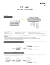
Recommended External Entrapment
Protection Sensors List
325
Bottom Edge
(if more than 4”)
PUBLIC
SECURE
Swing Gate Potential Entrapment Zones
Install Photo Eye
Protects Leading End
(EYE CLOSE)
5
4
3
2
1
1
6
1. Leading Edge
2. Bottom Edge Entry / Exit
3. Posts
4. Post Pivot / Pinch Points
5. Arm Movement
The sensors shown in the table below have been tested with Nice | HySecurity gate operators by an independent laboratory
and certifi ed to comply with UL 325 7th Edition. Select sensors from this list for UL compliant gate automation solutions.
Contact the sensor manufacturer for specifi c recommendations for use.
1414 support.hysecurity.com

Safety information
ELECTRICAL SAFETY
Turn gate operator and all circuit
breakers OFF before performing
maintenance on the gate operator
or making contact with output
receptacles.
Never insert any objects into output
receptacles during operation. The
possibility exists of electrical shock,
electrocution, or death.
Never let power wires lay in water.
Never use damaged or worn wire when connecting
equipment. Inspect for cuts in the insulation.
Never grab or touch a live power
cord or cable with wet hands. The
possibility exists of electrical shock,
electrocution or death.
Always make certain that proper
power has been selected for the job.
See Cable Selection Chart in this
manual.
GROUNDING SAFETY
Always make sure that electrical
circuits are properly grounded to a
suitable earth ground (ground rod)
per the National Electrical Code
(NEC) and local codes. Severe
injury or death by electrocution
can result from operating an
ungrounded operator.
Never use gas piping as an electrical ground.
BATTERY SAFETY
HySecurity operators use sealed Absorbed Glass Mat (AGM)
batteries and HySecurity highly recommends replacing used
batteries with new AGM-type batteries.
CAUTION
Batteries used with HySecurity gate operator contain
materials considered hazardous to environment.
Proper battery disposal is required by federal law.
Refer to Hazardous Waste Regulations federal
guidelines.
To reduce risk of fi re or injury to persons:
Observe polarity between batteries and charging circuit.
Never mix battery sizes, types, or brands. Charging circuit
on HySecurity DC operators is designed for AGM-type
batteries, not fl ooded lead acid-type batteries.
Exercise care in handling batteries. Be
aware metal found in rings, bracelets, and
keys can conduct electricity, short
batteries, and cause potential injury.
Do not open or mutilate batteries. Battery cells
contain corrosive materials which may cause
burns and other injuries. Material within
batteries is toxic.
Always dispose of batteries properly. Do not
place batteries in fire. Battery cells may
explode. Follow federal guidelines for proper
disposal of hazardous waste.
Always keep battery cables in good working
condition. Repair or replace all worn cables.
Replace batteries according to instructions
found in DC Battery Replacement.
Do not charge frozen battery. Battery can
explode. If frozen, warm the battery to at
least 61°F (16°C).
ENVIRONMENTAL SAFETY/HAZARDOUS
MATERIALS AND PROPER DISPOSAL
Decommissioning is a controlled process used to safely
retire a piece of equipment that is no longer
serviceable. If the equipment poses an
unacceptable and unrepairable safety risk due to
wear or damage or is no longer cost eff ective to
maintain (beyond life-cycle reliability) and is to be
decommissioned (demolition and dismantlement), be sure to
follow rules below.
Do not pour waste or oil directly onto the ground, down a
drain or into any water source.
Contact your country's Department of Public Works or
recycling agency in your area and arrange for proper
disposal of any electrical components, waste or oil
associated with this equipment.
When the life cycle of this equipment is over, remove battery
and bring to appropriate facility for lead reclamation. Use
safety precautions when handling batteries that contain
sulfuric acid.
When the life cycle of this equipment is over, it is
recommended that the frame and all other metal and plastic
parts be sent to a recycling center.
Metal and plastic recycling involves the collection of metal and
plastic from discarded products and its transformation into raw
materials to use in manufacturing a new product.
Recyclers and manufacturers alike promote the process
1515
MX3636-01 Rev. J ©2023

Safety information
of recycling metal and plastic. Using a metal and plastic
recycling center promotes energy cost savings.
WIND LOAD
When the IES (type A sensor) trips, it
sends a signal to gate operator to stop
and reverse direction. This feature may
be falsely triggered in excessively windy
conditions because wind itself, acting
over surface area of gate panel, can
provide necessary force to trigger IES.
CAUTION
Do not adjust IES sensitivity/Force setting to
accommodate for inappropriately designed gate
panels. Loss of IES sensitivity increases mechanical
wear on gate hardware and gate operator. It may also
pose a safety hazard. Compensating for wind loads by
adjusting IES may set IES sensitivity to a level which,
when encountering an obstruction, ignores obstruction
and fails to reverse direction.
MAINTENANCE OF GATE SYSTEMS
To keep your automated gate system performing both safely
and reliably it is important to ensure that the components of
that system are functioning properly.
At least monthly:
Disconnect the gate operator and manually move the
gate through its range of travel. Note any squeaks from
rollers or hinges or areas of binding. The gate should
travel smoothly and quietly throughout its range. If it
does not, contact a gate professional to correct the
problem.
Reconnect the gate operator and perform the following
tests:
•
With the gate opening, block any photo eyes and/
or depress any safety edges used to protect the
open direction. The gate should stop and/or reverse.
•
With the gate closing, block any photo eyes and/or
depress any safety edges used to protect the close
direction. The gate should stop and/or reverse.
•
Using a suitable obstruction in the path of the gate
(a solid, immovable object), run the gate in the open
direction until it contacts the obstruction. The gate
should stop and reverse, or it will just stop if a Type
C sensor is engaged before the Type A sensor is
tripped.
•
Using a suitable obstruction in the path of the gate
(a solid, immovable object), run the gate in the close
direction until it contacts the obstruction. The gate
should stop and reverse, or it will just stop if a Type
C sensor is engaged before the Type A sensor is
tripped.
NOTICE
For more information on Gate Safety, visit:
https://support.hysecurity.com/hc/en-us/
categories/360003177593-Safety.
1616 support.hysecurity.com

BreatHer Cap inStallation and grounding
The gate operator has a vent plug that keeps the hydraulic uid from spilling during shipment. The vent plug
must be replaced by the breather cap before operating the swing gate.
DANGER
Failure to perform the following procedure will cause premature pump shaft failure and void the
Limited Warranty.
1. Remove the vent plug and discard it.
2. Replace the vent plug with the breather cap.
.....
Refer to the Power section for more
information about the earth ground.
Consult local codes for proper
connection and depth of ground rod.
HydraSupply
Vent plug
Breather cap
Ground lug
1717
MX3636-01 Rev. J ©2023

emergenCy Stop Button
Make sure all users of the gate know where the emergency stop
button is located (see illustration). It complies with UL 325 Safety
Standards requirements.
Pressing the emergency stop button while the gate is opening or
closing disables the automatic close timer and stops gate travel.
Gate travel remains stopped until the operator receives another
open or close signal.
manual releaSe option
WARNING
Before attempting a manual release, make sure the gate is not in motion and power is disconnected
(turned OFF).
The manual release option can be found on the brake manifold.
To move the gate manually, turn OFF the power switch on the control box in the HydraSupply cabinet, and
then simply push the release lever, as shown in the illustration.
Emergency Stop
button
HydraSupply
Release position
Standard or Run
position
Brake manifold
HydraSwing 40, 40F, and 40 & 40F Twin
CAUTION
For the HydraSwing 80F or 150 models, pushing
close while using the manual release option may
cause an air pocket to form in the hydraulic
cylinder and cause overow from the reservoir.
If you notice uid leakage, stop gate travel
immediately and use the hand pump.
1818 support.hysecurity.com

Hand pump
A hand pump kit is used to manually operate the hydraulic mechanism that secures the gate. In the event of a
power failure, manual operation can be achieved by accessing the hydraulics cabinet. Follow the steps below
to open or close the gate:
NOTE: A manual release mechanism exists on the brake manifold assembly. Refer to Manual Release Option on page 18.
Open the Gate using the Hand Pump
1. Open the HydraSupply cabinet.
2. Turn the power switch OFF.
3. Locate the hand pump and the Knurled Knob on the Open Valve.
4. Firmly, pull and twist the knurled knob counterclockwise. Release the knob so that it remains in the
open position.
NOTE: If the valve re-seats itself, repeat the pull and twist in the opposite direction until the valve remains open.
5. Begin pumping the handle up and down. As hydraulic uid is
pumped into the cylinder, it begins to move the gate. It is a slow
process.
6. Continue pumping until the gate reaches full open position.
7. Turn the knurled knob so it springs back to the closed position.
Close the Gate using the Hand Pump
1. Check that the knurled knob is in the closed position. Begin
pumping the handle up and down. The gate slowly closes with
the pumping motion.
2. The gate will maintain its position whenever you stop pumping.
3. Continue pumping until the gate reaches the full closed position.
Knurled knob
.
.
.
.
.
.
.
.
.
.
HydraSwing 80F and 150 HydraSwing 40, 40F and Twin 40 & 40F
1919
MX3636-01 Rev. J ©2023

Power
How to wire the operator is presented in the Installation Instructions, but detailed information about the earth
and equipment ground, wiring to AC power and the availability of UPS systems are described in this section.
Supplemental documents to this section include:
• DC Power Supply with HyCharger DC • AC Power Supply with HyInverter AC
inStalling tHe eartH ground
An earth ground refers to the grounding rod and accompanying equipment ground which need to be installed
to safeguard against potential electrical shock and damage to personnel and equipment.
DANGER
The potential for lightning discharge exists with all gates, fences and gate operators. National Electric
Code (NEC) - Article 250 requires a separate earth ground in addition to the required equipment ground.
HySecurity recommends grounding the operator with a separate earth ground rod (or a similar device
in the case of crash products) to shield the operator against electromagnetism and other electrical signals
that may cause, erratic operation with, or damage to, the Smart Touch Controller and other electrical parts.
For earth grounding requirements in the U.S.A., refer
to the National Fire Protection Association (NFPA) 780
- Standard for the Installation of Lightning Protection
Systems. Highlights of the standard include:
• The ground rod must be UL listed copper-clad
steel, solid copper, hot-dipped galvanized
steel, or stainless steel. Minimum requirements:
⅝ inch (16 mm) diameter and 8 feet (244 cm) in
length.
• The ground rod is driven into the earth (refer to
local codes for proper depth requirements).
• The ground rod is electrically bonded to the
chassis with a single length of un-spliced 6
AWG copper wire less than 3 feet (91 cm) long.
Due to the large concrete foundation on crash
products, make the necessary adjustments to
accommodate for earth ground requirements.
• Local jurisdictions may impose other
requirements above the NEC, Article 250
and NFPA 780 Consult the local codes and
regulations regarding requirements in your
area.
NOTICE: Properly grounding the gate operator is critical to gate operator performance and the life of its electrical
components. Use sufcient wire size during installation. If you do not ground the operator with a separate earth
ground, you risk voiding the HySecurity Warranty.
.....
HydraSupply cabinet
Ground rod
Consult local
codes for
proper depth
Grade level
3 ft (91.4cm)
Maximum distance
Ground lug Control Box
Variable speed
Drive (VFD)
Power switch
2020 support.hysecurity.com
/