Asus P5G965 User manual

Category
Computer cases
Type
User manual

This manual is also suitable for

Asus P5G965 V-Series is an advanced PC barebone system that offers vast expandability with the latest computing technology, extensive connectivity with high-speed data transfer, and the ability to house multiple storage drives for data storage and retrieval.

Asus P5G965 V-Series is an advanced PC barebone system that offers vast expandability with the latest computing technology, extensive connectivity with high-speed data transfer, and the ability to house multiple storage drives for data storage and retrieval.

V-Series P5G965
ASUS PC (Desktop Barebone)
Installation manual
E2796
2
Installation manual
Rear panel features
Front panel features
REAR
S P K
LINE
IN
FRONT
MIC IN
SIDE
S P K
C T R
BASS
5.25-inch drive
bay cover
IEEE 1394 port
Power button
Reset button
HDD LED
USB 2.0 ports
Microphone port
3.5-inch drive bay
cover
Headphone port
PS/2 mouse port
Cover screw
PS/2 keyboard port
Parallel port
Voltage selector
Metal bracket lock
Power connector
E-SATA port
VGA port
USB 2.0 ports
8-channel
audio ports
Expansion slot
metal brackets
Power supply fan
Chassis fan vents
LAN (RJ-45) port
Cover screw
IEEE 1394 port
3
Installation manual
Selecting the voltage
The system’s power supply unit has a 115
V/230 V voltage selector switch located
beside the power connector. Use this
switch to select the appropriate system
input voltage according to the voltage
supply in your area.
If the voltage supply in your area is
100-127 V, set the switch to 115 V.
If the voltage supply in your area is
200-240 V, set the switch to 230 V.
CR2032 3V
Lithium Cell
CMOS Power
CD
Super
I/O
A
TX12V
AAFP
DDR DIMM_A1 (64 bit,240-pin module)
SB_PWR
USB78
USB56
CLRTC
PCI1
Intel
®
GMCH
945G
Intel
®
ICH7
DDR DIMM_A2 (64 bit,240-pin module)
DDR DIMM_B1 (64 bit,240-pin module)
DDR DIMM_B2 (64 bit,240-pin module)
CHA_FAN
CPU_FAN
EATXPWR
PCI2
SPDIF_OUT
Intel
82573L
PS/2KBMS
T: Mouse
B: Keyboard
PCIEX1_1
PCIEX16
COM1
PARALLEL PORT
VGA
PANEL
®
SATA1 SATA2
SATA4SATA3
FLOPPY
PRI_IDE
COM2
ALC882
TI
TSB43AB22A
ADH
LGA775
LAN_USB34
AUDIO
USB1
USB2
Bottom:
1394
Top:
IE1394_2
USB910
CHASSIS
Internal components
1. Front panel cover
2. 5.25-inch optical drive bays
3. Hard disk drive bay
4. Floppy disk drive bay
5. Power supply unit
6. CPU socket
7. DIMM sockets
8. ASUS motherboard
9. PCI Express x16 slot
10. PCI slots
11. PCI Express x1 slot
12. Metal bracket lock
6
1
2
3
4
12
10
7
8
5
11
9
4
Installation manual
Removing the side cover and
front panel assembly
1. Remove the cover screws on the rear panel.
2. Pull the side cover toward the rear panel until its hooks disengage from the
chassis tab holes. Set the side cover aside.
3. Locate the front panel assembly hooks, then lift them until they disengage
from the chassis.
4. Swing the front panel assembly to the right, until the hinge-like tabs on the
right side of the assembly are exposed.
5. Remove the front panel assembly, then set aside.
Air ductduct
1
1
2
2
4
3
4
4
3
3
3
Chassis tab holes
Installing a CPU
To prevent damage to the socket
pins, do not remove the PnP cap
unless you are installing a CPU.
To install a CPU:
1. Locate the CPU socket on the motherboard.
2. Press the load lever with your thumb
(A), then move it to the left (B) until it
is released from the retention tab.
A
B
Load lever
Retention tab
5
Installation manual
3. Lift the load lever in the direction of the
arrow to a 135º angle.
4. Lift the load plate with your thumb and
forenger to a 100º angle (4A), then push
the PnP cap from the load plate window to
remove (4B).
6. Close the load plate (A), then push
the load lever (B) until it snaps into the
retention tab.
5. Position the CPU over the socket, making
sure that the gold triangle is on the
bottom-left corner of the socket. Fit the
socket alignment key into the CPU notch.
Installing the CPU fan and heatsink assembly
The Intel
®
Pentium
®
4 LGA775 processor requires a specially designed heatsink
and fan assembly to ensure optimum thermal condition and performance.
To install the CPU heatsink and fan:
1. Place the heatsink on top of the installed
CPU, making sure that the four fasteners
match the holes on the motherboard.
2. Push down two fasteners at a time in a
diagonal sequence to secure the heatsink
and fan assembly in place.
3. When the fan and heatsink assembly is in
place, connect the CPU fan cable to the
connector on the motherboard.
1
A
B
A
B
1
3
4A
4B
Load plate
PnP cap
Gold
triangle
mark
Alignment key
A
B
6
Installation manual
Installing an expansion card
Installing a DIMM
1. Locate the DIMM sockets in the motherboard.
2. Unlock a DIMM socket by pressing the retaining clips outward.
3. Align a DIMM on the socket such that the notch on the DIMM matches the
break on the socket.
4. Push the DIMM to the socket until the retaining clips snap inward.
Unplug the power supply before adding or removing DIMMs. Failure to do
so may cause damage to the motherboard and/or components.
A DDR DIMM is keyed with a notch so that it ts in only one direction. Do not
force a DIMM into a socket to avoid damaging the DIMM.
2. Remove the metal bracket lock.1. Remove the metal cover opposite
the slot that you intend to use.
3. Insert the card connector to the
slot, then press the card rmly
until it ts in place.
4. Replace the metal bracket lock.
1
2
3
4
7
Installation manual
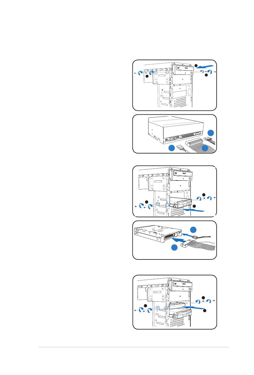
Installing storage drives
Optical drive
1. Place the chassis upright, then
remove the upper 5.25” drive bay
metal plate cover.
2. Insert the optical drive to the bay,
then carefully push the drive until its
screw holes align with the holes on
the bay.
3. Secure the optical drive with two
screws on both sides of the bay.
4. Connect the audio (A), IDE (B), and
power (C) plugs to connectors at
the back of the drive.
3
3
2
Floppy disk drive
1. Place the chassis upright, then
remove the lower 3.5” drive bay
metal plate cover.
2. Insert the oppy disk drive to the
bay, then carefully push the drive
until its screw holes align with the
holes on the bay.
3. Secure the oppy disk drive with
two screws on both sides of the
bay.
4. Connect the signal (A) and power
(B) plugs to connectors at the back
of the drive.
3
3
2
Hard disk drive
1. Place the chassis upright, then
remove the upper 3.5” drive bay
metal plate cover.
2. Insert the hard disk drive to the bay,
then carefully push the drive until its
screw holes align with the holes on
the bay.
3. Secure the hard disk drive with two
screws on both sides of the bay.
3
3
2
C
B
A
B
A
8
Installation manual
4. For SATA HDD: Connect the SATA
signal and power plugs to the
connectors at the back of the drive.
For IDE HDD: Connect the IDE and
power plugs to the connectors at the
back of the drive.
Removing the bay covers and reinstalling the
front panel assembly and side cover
If you installed an optical and/or oppy disk drive, remove the bay cover(s) on the
front panel assembly before reinstalling it to the chassis. To do this:
1. Locate the bay cover locks.
2. Press the locks outward to release
the bay cover.
3. Push the bay cover inward, then set
it aside.
4. Follow the same instructions to
remove the 3.5” drive bay cover.
Air duct
To reinstall the front panel assembly and side cover:
1. Insert the front panel assembly hinge-like tabs to the holes on the right side
of the chassis.
2. Swing the front panel assembly to the left, then insert the hooks to the
chassis until the front panel assembly ts in place.
3. Insert the six side cover hooks into the chassis tab holes .
4. Push the side cover to the direction of the front panel until it ts in place.
5. Secure the cover with two screws you removed earlier.
2
1
3
2
5
5
1
1
2
2
4
Chassis tab holes
  • Page 1 1
  • Page 2 2
  • Page 3 3
  • Page 4 4
  • Page 5 5
  • Page 6 6
  • Page 7 7
  • Page 8 8

Asus P5G965 User manual

Category
Computer cases
Type
User manual
This manual is also suitable for

Asus P5G965 V-Series is an advanced PC barebone system that offers vast expandability with the latest computing technology, extensive connectivity with high-speed data transfer, and the ability to house multiple storage drives for data storage and retrieval.

Ask a question and I''ll find the answer in the document

Finding information in a document is now easier with AI