6
TOOLS AND HARDWARE REQUIRED
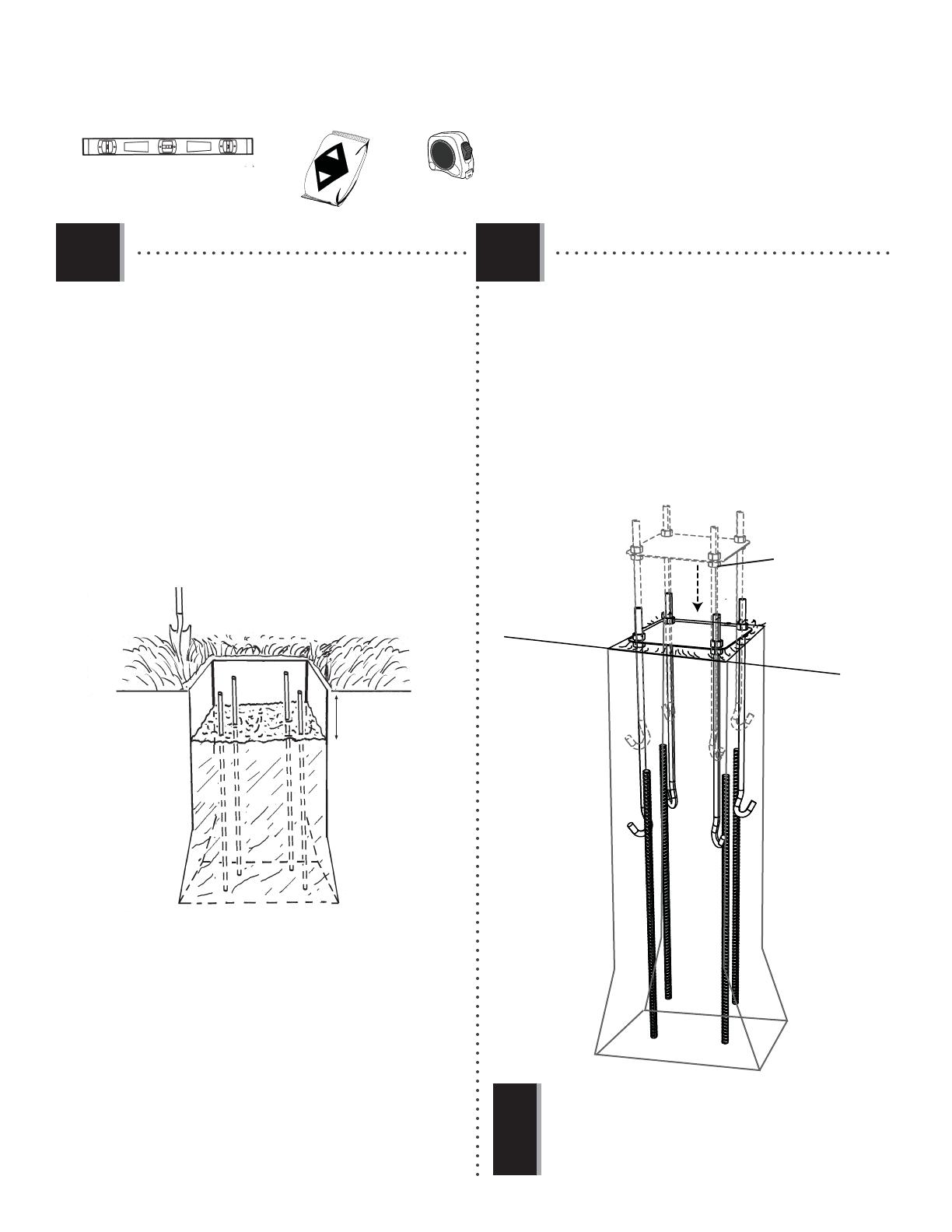
X SECTION 1 (CONTINUED)
• Center the Template (AKT) over the hole. Insert the
J-Bolts (AEI) into the concrete and agitate the Template
assembly to eliminate any air bubbles. Push the
J-Bolts into the cement until the Template is
resting flat against the cement. Form the cement
into a downward slope toward the playing surface
to allow water runoff. The lower four Hex Nuts (AOE)
will be in the concrete permanently. Clean off any
concrete on the Template or the exposed portion
of the J-Bolts. Using a carpenter’s level, ensure the
Template is square to the playing surface. Plate should
be level and about 1/2” above the playing surface
for water to drain off of the steel.
18” (20 cm)
AEZ
(80-lb Bag x 8)
• If you are using concrete mix, mix the concrete
according to the instructions on the bags. Please
note that a thicker mix of concrete will dry stronger.
Pour the concrete into the hole, stopping about
18” (46 cm) from the top of the hole. Push the
four pieces of 24” Rebar (AEZ) firmly to the bottom
of the hole. The Rebar should be arranged in a
square about 8” (20 cm) wide in the center of
the hole so each piece will be next to a J-Bolt
when it is placed in the cement. Finish filling
the hole to the top with concrete. The top of the
concrete should extend about 1/2” (13 mm)
above the playing surface and slope downward
toward the playing surface to allow water runoff.
1.3
AKT
AEI
AOE
Playing surface
!
• You are now finished with the initial assembly steps. DO NOT
PROCEED WITH THE ASSEMBLY until the concrete has fully cured.
Curing will take a minimum of 72 hours (3 days). In humid climates
or wet weather, allow additional time for the concrete to cure. Never
use the system without first following the cementing instructions.
1.4


