Page is loading ...

www.mellanox.com
Mellanox MetroX™Long Haul Systems
Hardware User Manual
Models: TX6240/TX6280
Rev 1.1

Document Number: MLNX-15-1402
Mellanox Technologies
2
Mellanox Technologies
350 Oakmead Parkway Suite 100
Sunnyvale, CA 94085
U.S.A.
www.mellanox.com
Tel: (408) 970-3400
Fax: (408) 970-3403
Mellanox Technologies, Ltd.
Hakidma 26
Ofer Industrial Park
Yokneam 2069200
Israel
www.mellanox.com
Tel: +972 (0)74 723 7200
Fax: +972 (0)4 959 3245
© Copyright 2015. Mellanox Technologies. All Rights Reserved.
Mellanox®, Mellanox logo, BridgeX®, ConnectX®, Connect-IB®, CoolBox®, CORE-Direct®, GPUDirect®, InfiniBridge®,
InfiniHost®, InfiniScale®, Kotura®, Kotura logo, MetroX®, MLNX-OS®, PhyX®, ScalableHPC®, SwitchX®, TestX®,
UFM®, Virtual Protocol Interconnect®, Voltaire® and Voltaire logo are registered trademarks of Mellanox Technologies,
Ltd.
CyPU™, ExtendX™, FabricIT™, FPGADirect™, HPC-X™, Mellanox Care™, Mellanox CloudX™, Mellanox NEO™,
Mellanox Open Ethernet™, Mellanox PeerDirect™, Mellanox Virtual Modular Switch™, MetroDX™, NVMeDirect™,
StPU™, Switch-IB™, Unbreakable-Link™ are trademarks of Mellanox Technologies, Ltd.
All other trademarks are property of their respective owners.
NOTE:
THIS HARDWARE, SOFTWARE OR TEST SUITE PRODUCT (“PRODUCT(S)”) AND ITS RELATED
DOCUMENTATION ARE PROVIDED BY MELLANOX TECHNOLOGIES “AS-IS” WITH ALL FAULTS OF ANY
KIND AND SOLELY FOR THE PURPOSE OF AIDING THE CUSTOMER IN TESTING APPLICATIONS THAT USE
THE PRODUCTS IN DESIGNATED SOLUTIONS. THE CUSTOMER'S MANUFACTURING TEST ENVIRONMENT
HAS NOT MET THE STANDARDS SET BY MELLANOX TECHNOLOGIES TO FULLY QUALIFY THE PRODUCT(S)
AND/OR THE SYSTEM USING IT. THEREFORE, MELLANOX TECHNOLOGIES CANNOT AND DOES NOT
GUARANTEE OR WARRANT THAT THE PRODUCTS WILL OPERATE WITH THE HIGHEST QUALITY. ANY
EXPRESS OR IMPLIED WARRANTIES, INCLUDING, BUT NOT LIMITED TO, THE IMPLIED WARRANTIES OF
MERCHANTABILITY, FITNESS FOR A PARTICULAR PURPOSE AND NONINFRINGEMENT ARE DISCLAIMED.
IN NO EVENT SHALL MELLANOX BE LIABLE TO CUSTOMER OR ANY THIRD PARTIES FOR ANY DIRECT,
INDIRECT, SPECIAL, EXEMPLARY, OR CONSEQUENTIAL DAMAGES OF ANY KIND (INCLUDING, BUT NOT
LIMITED TO, PAYMENT FOR PROCUREMENT OF SUBSTITUTE GOODS OR SERVICES; LOSS OF USE, DATA,
OR PROFITS; OR BUSINESS INTERRUPTION) HOWEVER CAUSED AND ON ANY THEORY OF LIABILITY,
WHETHER IN CONTRACT, STRICT LIABILITY, OR TORT (INCLUDING NEGLIGENCE OR OTHERWISE)
ARISING IN ANY WAY FROM THE USE OF THE PRODUCT(S) AND RELATED DOCUMENTATION EVEN IF
ADVISED OF THE POSSIBILITY OF SUCH DAMAGE.

Rev 1.1
Mellanox Technologies
3
Table of Contents
Revision History . . . . . . . . . . . . . . . . . . . . . . . . . . . . . . . . . . . . . . . . . . . . . . . . . . . . . . . . . . . 9
About this Manual . . . . . . . . . . . . . . . . . . . . . . . . . . . . . . . . . . . . . . . . . . . . . . . . . . . . . . . . 10
Chapter 1 Introduction to Mellanox MetroX™Long Haul Systems. . . . . . . . . . . . . . . 11
1.1 Overview . . . . . . . . . . . . . . . . . . . . . . . . . . . . . . . . . . . . . . . . . . . . . . . . . . . . . . . 11
1.2 Speed and Switching . . . . . . . . . . . . . . . . . . . . . . . . . . . . . . . . . . . . . . . . . . . . . . 11
1.3 Management Interfaces and FRUs. . . . . . . . . . . . . . . . . . . . . . . . . . . . . . . . . . . . 12
1.4 Features . . . . . . . . . . . . . . . . . . . . . . . . . . . . . . . . . . . . . . . . . . . . . . . . . . . . . . . . 12
1.4.1 Network Management Feature . . . . . . . . . . . . . . . . . . . . . . . . . . . . . . . . . . . . . . . 12
1.5 Certifications . . . . . . . . . . . . . . . . . . . . . . . . . . . . . . . . . . . . . . . . . . . . . . . . . . . . 12
1.6 Ordering Information. . . . . . . . . . . . . . . . . . . . . . . . . . . . . . . . . . . . . . . . . . . . . . 13
Chapter 2 Installation . . . . . . . . . . . . . . . . . . . . . . . . . . . . . . . . . . . . . . . . . . . . . . . . . . . . 14
2.1 Safety Warnings. . . . . . . . . . . . . . . . . . . . . . . . . . . . . . . . . . . . . . . . . . . . . . . . . . 14
2.2 Air Flow. . . . . . . . . . . . . . . . . . . . . . . . . . . . . . . . . . . . . . . . . . . . . . . . . . . . . . . . 15
2.3 Package Contents. . . . . . . . . . . . . . . . . . . . . . . . . . . . . . . . . . . . . . . . . . . . . . . . . 17
2.4 Mounting Options . . . . . . . . . . . . . . . . . . . . . . . . . . . . . . . . . . . . . . . . . . . . . . . . 19
2.4.1 TX6240/TX6280 Mounting . . . . . . . . . . . . . . . . . . . . . . . . . . . . . . . . . . . . . . . . . 19
2.4.2 MEX6200 Mounting . . . . . . . . . . . . . . . . . . . . . . . . . . . . . . . . . . . . . . . . . . . . . . . 24
2.5 Grounding . . . . . . . . . . . . . . . . . . . . . . . . . . . . . . . . . . . . . . . . . . . . . . . . . . . . . . 26
2.5.1 TX6240/TX6280 Grounding. . . . . . . . . . . . . . . . . . . . . . . . . . . . . . . . . . . . . . . . . 26
2.5.2 MEX6200 Grounding . . . . . . . . . . . . . . . . . . . . . . . . . . . . . . . . . . . . . . . . . . . . . . 26
2.6 Connecting the TX6240/TX6280 System to the MEX6200 Unit . . . . . . . . . . . . 27
2.7 Cable Installation. . . . . . . . . . . . . . . . . . . . . . . . . . . . . . . . . . . . . . . . . . . . . . . . . 30
2.8 Initial Power On. . . . . . . . . . . . . . . . . . . . . . . . . . . . . . . . . . . . . . . . . . . . . . . . . . 31
2.8.1 TX6240/TX6280 Initial Power On . . . . . . . . . . . . . . . . . . . . . . . . . . . . . . . . . . . . 31
2.8.2 MEX6200 Initial Power On . . . . . . . . . . . . . . . . . . . . . . . . . . . . . . . . . . . . . . . . . 33
2.9 System Bring-Up . . . . . . . . . . . . . . . . . . . . . . . . . . . . . . . . . . . . . . . . . . . . . . . . 33
2.9.1 Configuring Network Attributes . . . . . . . . . . . . . . . . . . . . . . . . . . . . . . . . . . . . . . 33
2.9.2 Remote Connection. . . . . . . . . . . . . . . . . . . . . . . . . . . . . . . . . . . . . . . . . . . . . . . . 36
2.10 FRU Replacements . . . . . . . . . . . . . . . . . . . . . . . . . . . . . . . . . . . . . . . . . . . . . . . 37
2.10.1 TX6240/TX6280 Power Supply and Fans . . . . . . . . . . . . . . . . . . . . . . . . . . . . . . 37
2.10.2 MEX6200 Power Supply and Fan. . . . . . . . . . . . . . . . . . . . . . . . . . . . . . . . . . . . . 40
Chapter 3 Interfaces . . . . . . . . . . . . . . . . . . . . . . . . . . . . . . . . . . . . . . . . . . . . . . . . . . . . . 41
3.1 Data Interfaces. . . . . . . . . . . . . . . . . . . . . . . . . . . . . . . . . . . . . . . . . . . . . . . . . . . 41
3.1.1 RS232 (Console) . . . . . . . . . . . . . . . . . . . . . . . . . . . . . . . . . . . . . . . . . . . . . . . . . . 41
3.1.2 Management . . . . . . . . . . . . . . . . . . . . . . . . . . . . . . . . . . . . . . . . . . . . . . . . . . . . . 41
3.1.3 USB. . . . . . . . . . . . . . . . . . . . . . . . . . . . . . . . . . . . . . . . . . . . . . . . . . . . . . . . . . . . 42
3.1.4 I2C. . . . . . . . . . . . . . . . . . . . . . . . . . . . . . . . . . . . . . . . . . . . . . . . . . . . . . . . . . . . . 42
3.1.5 Reset Button . . . . . . . . . . . . . . . . . . . . . . . . . . . . . . . . . . . . . . . . . . . . . . . . . . . . . 42
3.2 MEX6200 Interfaces . . . . . . . . . . . . . . . . . . . . . . . . . . . . . . . . . . . . . . . . . . . . . . 43
3.2.1 LINK Ports and Connectors . . . . . . . . . . . . . . . . . . . . . . . . . . . . . . . . . . . . . . . . . 43
3.2.2 Management Ports and Connectors. . . . . . . . . . . . . . . . . . . . . . . . . . . . . . . . . . . . 47

Mellanox Technologies
4
3.2.3 Facility Protection for MEX6200 . . . . . . . . . . . . . . . . . . . . . . . . . . . . . . . . . . . . . 49
3.2.4 Fiber Protection. . . . . . . . . . . . . . . . . . . . . . . . . . . . . . . . . . . . . . . . . . . . . . . . . . . 51
3.3 LEDs . . . . . . . . . . . . . . . . . . . . . . . . . . . . . . . . . . . . . . . . . . . . . . . . . . . . . . . . . . 52
3.3.1 TX6240/TX6280 LED Notifications . . . . . . . . . . . . . . . . . . . . . . . . . . . . . . . . . . 52
3.3.2 MEX6200 LED Notifications . . . . . . . . . . . . . . . . . . . . . . . . . . . . . . . . . . . . . . . . 57
3.4 Inventory Pull-out Tab. . . . . . . . . . . . . . . . . . . . . . . . . . . . . . . . . . . . . . . . . . . . . 58
Chapter 4 Software Management. . . . . . . . . . . . . . . . . . . . . . . . . . . . . . . . . . . . . . . . . . . 59
4.1 Upgrading Software . . . . . . . . . . . . . . . . . . . . . . . . . . . . . . . . . . . . . . . . . . . . . . 59
Chapter 5 Troubleshooting . . . . . . . . . . . . . . . . . . . . . . . . . . . . . . . . . . . . . . . . . . . . . . . . 60
5.1 TX6240/TX6280 Troubleshooting Instructions . . . . . . . . . . . . . . . . . . . . . . . . . 60
5.2 MEX6200 Troubleshooting Instructions . . . . . . . . . . . . . . . . . . . . . . . . . . . . . . . 62
Chapter 6 Specifications . . . . . . . . . . . . . . . . . . . . . . . . . . . . . . . . . . . . . . . . . . . . . . . . . . 65
6.1 TX6240 System- Standalone . . . . . . . . . . . . . . . . . . . . . . . . . . . . . . . . . . . . . . . . 65
6.2 TX6280 System - Standalone . . . . . . . . . . . . . . . . . . . . . . . . . . . . . . . . . . . . . . . 66
6.3 MEX6200 WDM Unit . . . . . . . . . . . . . . . . . . . . . . . . . . . . . . . . . . . . . . . . . . . . . 67
Appendix A Accessory and Replacement Parts . . . . . . . . . . . . . . . . . . . . . . . . . . . . . . . 68
Appendix B Thermal Threshold Definitions . . . . . . . . . . . . . . . . . . . . . . . . . . . . . . . . . 69
Appendix C Interface Specifications . . . . . . . . . . . . . . . . . . . . . . . . . . . . . . . . . . . . . . . . 70
C.1 QSFP Interface . . . . . . . . . . . . . . . . . . . . . . . . . . . . . . . . . . . . . . . . . . . . . . . . 70
C.2 RJ-45 CONSOLE and I2C Interface . . . . . . . . . . . . . . . . . . . . . . . . . . . . . . . 72
C.3 RJ45 to DB9 Harness Pinout . . . . . . . . . . . . . . . . . . . . . . . . . . . . . . . . . . . . . 73
Appendix D Disassembly and Disposal . . . . . . . . . . . . . . . . . . . . . . . . . . . . . . . . . . . . . . 74
D.1 Disassembly Procedure . . . . . . . . . . . . . . . . . . . . . . . . . . . . . . . . . . . . . . . . . 74
D.2 Disposal . . . . . . . . . . . . . . . . . . . . . . . . . . . . . . . . . . . . . . . . . . . . . . . . . . . . . 74
Appendix E Safety Warnings (Multiple Languages) . . . . . . . . . . . . . . . . . . . . . . . . . . . 75
E.1 Nordic Countries Notices . . . . . . . . . . . . . . . . . . . . . . . . . . . . . . . . . . . . . . . . 75
E.2 Installation Safety Warnings (English) . . . . . . . . . . . . . . . . . . . . . . . . . . . . . 75
E.3 (תירבע) הנקתהב תוחיטב תורהזא . . . . . . . . . . . . . . . . . . . . . . . . . . . . . . . . . . . . . . 78
E.4 安裝安全性警告 (Chinese) . . . . . . . . . . . . . . . . . . . . . . . . . . . . . . . . . . . . . . 82
E.5 Avertissements de sécurité pour l'installation (French) . . . . . . . . . . . . . . . . . 85
E.6 Installation Sicherheitshinweise(German) . . . . . . . . . . . . . . . . . . . . . . . . . . . 88
E.7 Advertencias de seguridad de instalación (Spanish) . . . . . . . . . . . . . . . . . . . 92
E.8 Предупреждения по технике безопасности при установке (Russian) . . . 95
E.9 Avertismente privind siguranţa la instalare (Romanian) . . . . . . . . . . . . . . . . 98
E.10 Sigurnosna upozorenja za instaliranje (Croatian). . . . . . . . . . . . . . . . . . . . . 102
E.11 Avvertenze di sicurezza per l’installazione (italiano) . . . . . . . . . . . . . . . . . 105
E.12 Montaj Güvenlik Uyarıları (Türkçe) . . . . . . . . . . . . . . . . . . . . . . . . . . . . . . 109

Rev 1.1
Mellanox Technologies
5
List of Figures
Figure 1: Long Haul TX6240/TX6280 Front Side View . . . . . . . . . . . . . . . . . . . . . . . . . . . . . . . . .11
Figure 2: Air Flow Direction Marking - Connector Side Inlet to Power Side Outlet . . . . . . . . . . .16
Figure 3: Air Flow Direction Marking - Power Side Inlet to Connector Side Outlet . . . . . . . . . . .16
Figure 4: Rack Rail Kit Parts . . . . . . . . . . . . . . . . . . . . . . . . . . . . . . . . . . . . . . . . . . . . . . . . . . . . . .19
Figure 5: Screwing on the Rail . . . . . . . . . . . . . . . . . . . . . . . . . . . . . . . . . . . . . . . . . . . . . . . . . . . . .20
Figure 6: Inserting the Caged Nuts . . . . . . . . . . . . . . . . . . . . . . . . . . . . . . . . . . . . . . . . . . . . . . . . .21
Figure 7: Slide the Rail into the Rail Slide . . . . . . . . . . . . . . . . . . . . . . . . . . . . . . . . . . . . . . . . . . .21
Figure 8: Installing the Slides . . . . . . . . . . . . . . . . . . . . . . . . . . . . . . . . . . . . . . . . . . . . . . . . . . . . .22
Figure 9: System Placement in the Rack . . . . . . . . . . . . . . . . . . . . . . . . . . . . . . . . . . . . . . . . . . . . .23
Figure 10: Installation Completed . . . . . . . . . . . . . . . . . . . . . . . . . . . . . . . . . . . . . . . . . . . . . . . . . . .23
Figure 11: Rack Installation Kit . . . . . . . . . . . . . . . . . . . . . . . . . . . . . . . . . . . . . . . . . . . . . . . . . . . . .24
Figure 12: Rack Mount Brackets . . . . . . . . . . . . . . . . . . . . . . . . . . . . . . . . . . . . . . . . . . . . . . . . . . . .24
Figure 13: Brackets Attached to the MEX6200 Unitt . . . . . . . . . . . . . . . . . . . . . . . . . . . . . . . . . . . .25
Figure 14: Attaching the Brackets to the Rack . . . . . . . . . . . . . . . . . . . . . . . . . . . . . . . . . . . . . . . . .25
Figure 15: Installed Fiber Tray . . . . . . . . . . . . . . . . . . . . . . . . . . . . . . . . . . . . . . . . . . . . . . . . . . . . .25
Figure 16: Grounding the MEX6200 . . . . . . . . . . . . . . . . . . . . . . . . . . . . . . . . . . . . . . . . . . . . . . . . .27
Figure 17: MEX6200/TX6240 Connectivity . . . . . . . . . . . . . . . . . . . . . . . . . . . . . . . . . . . . . . . . . .28
Figure 18: MEX6200/TX6280 Connectivity . . . . . . . . . . . . . . . . . . . . . . . . . . . . . . . . . . . . . . . . . .29
Figure 19: MetroX E2E Connectivity . . . . . . . . . . . . . . . . . . . . . . . . . . . . . . . . . . . . . . . . . . . . . . . .29
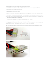
Figure 20: Breakout or Fanout Cable . . . . . . . . . . . . . . . . . . . . . . . . . . . . . . . . . . . . . . . . . . . . . . . . .30
Figure 21: System Status LEDs 5 Minutes After Power On . . . . . . . . . . . . . . . . . . . . . . . . . . . . . . .32
Figure 22: Two Power Inlets - Electric Caution Notifications . . . . . . . . . . . . . . . . . . . . . . . . . . . . .32
Figure 23: Power Supply Unit Extraction . . . . . . . . . . . . . . . . . . . . . . . . . . . . . . . . . . . . . . . . . . . . .38
Figure 24: PS Unit Pulled Out . . . . . . . . . . . . . . . . . . . . . . . . . . . . . . . . . . . . . . . . . . . . . . . . . . . . . .38
Figure 25: Fan Module Latches . . . . . . . . . . . . . . . . . . . . . . . . . . . . . . . . . . . . . . . . . . . . . . . . . . . . .39
Figure 26: MEX6200 Power Supply and Fan Unit . . . . . . . . . . . . . . . . . . . . . . . . . . . . . . . . . . . . . .40
Figure 27: MEX6200 Front Panel . . . . . . . . . . . . . . . . . . . . . . . . . . . . . . . . . . . . . . . . . . . . . . . . . . .43
Figure 28: MEX6200 with 8 Unprotected Transponders . . . . . . . . . . . . . . . . . . . . . . . . . . . . . . . . . .45
Figure 29: External ALARM Diagram . . . . . . . . . . . . . . . . . . . . . . . . . . . . . . . . . . . . . . . . . . . . . . .47
Figure 30: MEX6200 with 4 Protected Transponders . . . . . . . . . . . . . . . . . . . . . . . . . . . . . . . . . . . .50
Figure 31: MEX6200 with Transponder Protection . . . . . . . . . . . . . . . . . . . . . . . . . . . . . . . . . . . . .51
Figure 32: Fiber Protection with Optical Switch . . . . . . . . . . . . . . . . . . . . . . . . . . . . . . . . . . . . . . . .51
Figure 33: MEX6200 with Optical Switch . . . . . . . . . . . . . . . . . . . . . . . . . . . . . . . . . . . . . . . . . . . .51
Figure 34: System Status LEDs - Front and Rear sides . . . . . . . . . . . . . . . . . . . . . . . . . . . . . . . . . . .52
Figure 35: Fan Status LED - Front and Rear sides . . . . . . . . . . . . . . . . . . . . . . . . . . . . . . . . . . . . . .53
Figure 36: Power Status LED . . . . . . . . . . . . . . . . . . . . . . . . . . . . . . . . . . . . . . . . . . . . . . . . . . . . . .54

Mellanox Technologies
6
Figure 37: Rear Side Panel . . . . . . . . . . . . . . . . . . . . . . . . . . . . . . . . . . . . . . . . . . . . . . . . . . . . . . . .55
Figure 38: Port LEDs . . . . . . . . . . . . . . . . . . . . . . . . . . . . . . . . . . . . . . . . . . . . . . . . . . . . . . . . . . . . .56
Figure 39: Pull-out Tab . . . . . . . . . . . . . . . . . . . . . . . . . . . . . . . . . . . . . . . . . . . . . . . . . . . . . . . . . . .58
Figure 40: QSFP Connector Male and Female Views . . . . . . . . . . . . . . . . . . . . . . . . . . . . . . . . . . . .71
Figure 41: RJ45 to DB9 Harness Pinout . . . . . . . . . . . . . . . . . . . . . . . . . . . . . . . . . . . . . . . . . . . . . .73

Rev 1.1
Mellanox Technologies
7
List of Tables
Table 1: Revision History Table . . . . . . . . . . . . . . . . . . . . . . . . . . . . . . . . . . . . . . . . . . . . . . . . . . . .9
Table 2: References . . . . . . . . . . . . . . . . . . . . . . . . . . . . . . . . . . . . . . . . . . . . . . . . . . . . . . . . . . . .10
Table 3: Speed and Switching Capabilities . . . . . . . . . . . . . . . . . . . . . . . . . . . . . . . . . . . . . . . . . .11
Table 4: Management Interfaces and FRUs . . . . . . . . . . . . . . . . . . . . . . . . . . . . . . . . . . . . . . . . . .12
Table 5: Ordering Part Numbers (OPNs) . . . . . . . . . . . . . . . . . . . . . . . . . . . . . . . . . . . . . . . . . . . .13
Table 6: Air Flow Label Legend . . . . . . . . . . . . . . . . . . . . . . . . . . . . . . . . . . . . . . . . . . . . . . . . . . .15
Table 7: Installation Kit Options . . . . . . . . . . . . . . . . . . . . . . . . . . . . . . . . . . . . . . . . . . . . . . . . . .19
Table 8: Serial Terminal Program Configuration . . . . . . . . . . . . . . . . . . . . . . . . . . . . . . . . . . . . . .33
Table 9: Configuration Wizard Session - DHCP . . . . . . . . . . . . . . . . . . . . . . . . . . . . . . . . . . . . . .34
Table 10: Configuration Wizard Session - Static IP Configuration . . . . . . . . . . . . . . . . . . . . . . . . .35
Table 11: Link Port Specification . . . . . . . . . . . . . . . . . . . . . . . . . . . . . . . . . . . . . . . . . . . . . . . . . . .43
Table 12: Uplink LINK Port Specifications . . . . . . . . . . . . . . . . . . . . . . . . . . . . . . . . . . . . . . . . . . .44
Table 13: Service LINK Port Specifications . . . . . . . . . . . . . . . . . . . . . . . . . . . . . . . . . . . . . . . . . .44
Table 14: MEX6200 Services . . . . . . . . . . . . . . . . . . . . . . . . . . . . . . . . . . . . . . . . . . . . . . . . . . . . . .44
Table 15: COM Port Specification . . . . . . . . . . . . . . . . . . . . . . . . . . . . . . . . . . . . . . . . . . . . . . . . . .45
Table 16: COM Port Specification . . . . . . . . . . . . . . . . . . . . . . . . . . . . . . . . . . . . . . . . . . . . . . . . . .45
Table 17: ALARM Interfaces, Pin Function . . . . . . . . . . . . . . . . . . . . . . . . . . . . . . . . . . . . . . . . . .46
Table 18: MNG Port Specifications . . . . . . . . . . . . . . . . . . . . . . . . . . . . . . . . . . . . . . . . . . . . . . . . .47
Table 19: Control Connector Wiring . . . . . . . . . . . . . . . . . . . . . . . . . . . . . . . . . . . . . . . . . . . . . . . .48
Table 20: ETH Port Connector, Pin Functions . . . . . . . . . . . . . . . . . . . . . . . . . . . . . . . . . . . . . . . . .48
Table 21: MNG Port Specifications . . . . . . . . . . . . . . . . . . . . . . . . . . . . . . . . . . . . . . . . . . . . . . . . .49
Table 22: LINK Ports in Protected Configuration . . . . . . . . . . . . . . . . . . . . . . . . . . . . . . . . . . . . . .50
Table 23: Status LEDs . . . . . . . . . . . . . . . . . . . . . . . . . . . . . . . . . . . . . . . . . . . . . . . . . . . . . . . . . . .52
Table 24: System Status LED Assignments . . . . . . . . . . . . . . . . . . . . . . . . . . . . . . . . . . . . . . . . . . .53
Table 25: Fan Status LED Assignments . . . . . . . . . . . . . . . . . . . . . . . . . . . . . . . . . . . . . . . . . . . . . .54
Table 26: Power Supply Unit Status LED Assignments . . . . . . . . . . . . . . . . . . . . . . . . . . . . . . . . .55
Table 27: Bad Port LED Assignments . . . . . . . . . . . . . . . . . . . . . . . . . . . . . . . . . . . . . . . . . . . . . . .55
Table 28: Port LEDs in Ethernet System Mode . . . . . . . . . . . . . . . . . . . . . . . . . . . . . . . . . . . . . . . .56
Table 29: Port LEDs in InfiniBand System Mode . . . . . . . . . . . . . . . . . . . . . . . . . . . . . . . . . . . . . .56
Table 30: MEX6200 LEDs . . . . . . . . . . . . . . . . . . . . . . . . . . . . . . . . . . . . . . . . . . . . . . . . . . . . . . . .57
Table 31: Long Haul Troubleshooting . . . . . . . . . . . . . . . . . . . . . . . . . . . . . . . . . . . . . . . . . . . . . . .60
Table 32: MEX6200 Troubleshooting . . . . . . . . . . . . . . . . . . . . . . . . . . . . . . . . . . . . . . . . . . . . . . .62
Table 33: TX6240 Specifications . . . . . . . . . . . . . . . . . . . . . . . . . . . . . . . . . . . . . . . . . . . . . . . . . . .65
Table 34: TX6280 Specifications . . . . . . . . . . . . . . . . . . . . . . . . . . . . . . . . . . . . . . . . . . . . . . . . . . .66
Table 35: MEX6200 Specifications . . . . . . . . . . . . . . . . . . . . . . . . . . . . . . . . . . . . . . . . . . . . . . . . .67
Table 36: OPNs for Replacement Parts . . . . . . . . . . . . . . . . . . . . . . . . . . . . . . . . . . . . . . . . . . . . . .68


Rev 1.1
Mellanox Technologies
9
Revision History
Table 1 - Revision History Table
Date Revision Description
June 2015 1.2 Added Hebrew safety warnings
Added Japan VCCI Statement
Updated “Specifications”
Updated “Mounting Options”
December 2014 1.1 Updated Section 2.3 Package Contents
January 2015 1.0 First release of the new edition

Rev 1.1
Mellanox Technologies
10
About this Manual
This manual describes the installation and basic use of the Mellanox Long Haul systems.
Intended Audience
This manual is intended for IT managers and system administrators.
References
Conventions
The following icons are used throughout this document to indicate information that is important
to the user.
Table 2 - References
Document Description
SwitchX® Switch System
Hardware Release Notes
For possible hardware issues see the switch support product page. This docu-
ment can be found on the support web page for this product.
MLNX-OS® User Manual This document contains information regarding configuring and managing
MLNX-OS software- see http://www.mellanox.com/page/mlnx_os.
This icon makes recommendations to the user.
This icon indicates information that is helpful to the user.
This icon indicates a situation that can potentially cause personal injury or damage to
hardware or software.
Risk of electric shock!

Introduction to Mellanox MetroX™Long Haul Systems Rev 1.1
Mellanox Technologies
11
1 Introduction to Mellanox MetroX™Long Haul Systems
1.1 Overview
Mellanox MetroX series extends Mellanox’s RDMA solutions for high-performance technology
to local, campus and metro applications. It enables data sharing and support for disaster recovery,
40Gb/s RDMA execution over distant sites - up to 80km using WDM long-haul transceivers.
While InfiniBand products have been traditionally deployed for their high-performance intercon-
nect benefits within the data center, Mellanox MetroX systems, implementing long-haul Infini-
Band, enable connecting between data centers deployed across multiple geographically
distributed sites, extending the same world-leading interconnect benefits of InfiniBand beyond
local data centers and storage clusters.
Mellanox’s MetroX is the perfect cost-effective, low power, easily managed and scalable solu-
tion that enables today’s data centers and storage to run over local and distributed InfiniBand fab-
rics, managed as a single unified network infrastructure. The TX6240 and TX6280 systems,
which implement long-haul InfiniBand, can transfer data up to distances of 40km and 80km,
respectively. The systems enable aggregate data and storage networking over a single, consoli
-
dated InfiniBand fabric. The long-haul InfiniBand technology guarantees high-performance,
high-volume data sharing between distant sites, enabling existing data centers’ expansion, disas
-
ter recovery, data mirroring and campus connectivity.
MetroX enables a campus network to assemble large aggregate clusters, all connected and easily
managed by an InfiniBand Subnet Manager - an embedded manager, OpenSM, or using Mella
-
nox’s Unified Fabric Manager (UFM®).
Figure 1: Long Haul TX6240/TX6280 Front Side View
1.2 Speed and Switching
Table 3 describes maximum throughput and interface speed per system model.
Table 3 - Speed and Switching Capabilities
System Model
10GbE* SFP+
Interfaces
40/56GbE QSFP+ Interfaces Throughput
TX6240 N/A 2 FDR10 QSFP+ uplink
2 FDR QSFP+ downlink
80Gb/s

Introduction to Mellanox MetroX™Long Haul SystemsRev 1.1
Mellanox Technologies
12
*The switches can support 10Gb/s interfaces using QSFP to SFP adapters
1.3 Management Interfaces and FRUs
Table 4 lists the various management interfaces and available replacement parts per system
model.
1.4 Features
1.4.1 Network Management Feature
For a full feature list, refer to the product brief of the relevant system:
1.5 Certifications
The list of certifications (such as EMC, Safety and others) per system for different regions of the
world is located on the Mellanox website at:
http://www.mellanox.com/page/environmental_compliance
TX6280 N/A 1 FDR10 QSFP+ uplink
1 FDR QSFP+ downlink
40Gb/s
Table 4 - Management Interfaces and FRUs
System
Model
USB
MGT
Ports
Qty.
MGT
Ports
Location
I
2
C
Console
Replaceable
PSU
Replaceable
Fan
TX6240 Front 2 Front (x2) Rear Front 2 FRUs 1 FRU
TX6280 Front 2 Front (x2) Rear Front 2 FRUs 1 FRU
System
Model
USB
TX6240 http://www.mellanox.com/related-docs/prod_long_haul_systems/MetroX_TX6240.pdf
TX6280 http://www.mellanox.com/related-docs/prod_long_haul_systems/MetroX_TX6280.pdf
Table 3 - Speed and Switching Capabilities
System Model
10GbE* SFP+
Interfaces
40/56GbE QSFP+ Interfaces Throughput

Introduction to Mellanox MetroX™Long Haul Systems Rev 1.1
Mellanox Technologies
13
1.6 Ordering Information
the following table lists ordering information for the available systems. Please pay attention to
the airflow direction when ordering your system. For more details, see
“Air Flow” on page 15._
Table 5 - Ordering Part Numbers (OPNs)
System
Model
OPN Description
TX6240 MTX6240-2F_BL MetroX™ 40km WDM lossless long haul 40G system bundle, 2 long-haul QSFP+
ports, PSU side to connector side airflow, RoHS6
TX6280 MTX6280-2F_BL MetroX™ 80km WDM lossless long haul 40G system bundle, 1 long-haul QSFP+
port, PSU side to connector side airflow, RoHS6

InstallationRev 1.1
Mellanox Technologies
14
2Installation
Installation and initialization of the system require attention to the normal mechanical, power,
and thermal precautions for rack-mounted equipment.
The installation procedure for the Metrox system involves the following phases:
1. Follow the safety warnings in Section E.2,“Installation Safety Warnings (English),” on page
75.
2. Pay attention to the air flow consideration within the system and rack - refer to “Air Flow” on
page 15.
3. Make sure that none of the package contents is missing or damaged - see “Package Contents”
on page 17
4. Mount the system to the rack - see “Mounting Options” on page 19.
5. Ground the system, refer to “Grounding” on page 26.
6. Connect the WDFM
7. Power on the system - refer to “Initial Power On” on page 31
8. Perform system bring-up - see “System Bring-Up” on page 33
FRU replacements are described in Section 2.10 on page 37.
2.1 Safety Warnings
Prior to the installation, please review the safety warnings as follows:
For Nordic Countries Notices, see .Section E.1,“Nordic Countries Notices,” on page 75
For Safety Warnings in English, see Section E.2,“Installation Safety Warnings (English),” on
page 75.
For Safety Warnings in Hebrew, see Section E.3, “(תירבע) הנקתהב תוחיטב תורהזא,” on page 78.
For Safety Warnings in Chinese, see page 82.
For Safety Warnings in French, see Section E.5, “Avertissements de sécurité pour l'installation
(French),” on page 85.
For Safety Warnings in German, Section E.6, “Installation Sicherheitshinweise(German),” on
page 88.
For Safety Warnings in Spanish, see Section E.7, “Advertencias de seguridad de instalación
(Spanish),” on page 92.
For Safety Warnings in Russian, see Section E.8, “Предупреждения по технике безопасности
при установке (Russian),” on page 95.
For Safety Warnings in Romanian, see Section E.9, “Avertismente privind siguranţa la instalare
(Romanian),” on page 98.
The rack mounting holes conform to the EIA-310 standard for 19-inch racks. Take
precautions to guarantee proper ventilation in order to maintain good airflow at ambi
-
ent temperature.

Installation Rev 1.1
Mellanox Technologies
15
For Safety Warnings in Croatian, see Section E.10, “Sigurnosna upozorenja za instaliranje (Croa-
tian),” on page 102.
For Safety Warnings in Italian, see Section E.11, “Avvertenze di sicurezza per l’installazione
(italiano),” on page 105.
For Safety Warnings in Turkish see Section E.12, “Montaj Güvenlik Uyarıları (Türkçe),” on
page 109.
2.2 Air Flow
Mellanox systems are offered with two air flow patterns:
• Connector (front) side inlet to power side outlet - marked with red labels on the power
supply side as shown in
Figure 2.
• Power (rear) side inlet to connector side outlet - marked with blue labels on the power
supply side as shown in
Figure 3.
Table 6 provides an air flow label color legend and respective OPN designations,
All servers and systems in the same rack should be planned with the same air-
flow direction.
All FRU components need to have the same air flow direction. A mismatch in
the air flow will affect the heat dissipation.
Table 6 - Air Flow Label Legend
Direction
Label OPN
Designation
Description
R Connector side inlet to
power side outlet. Red
labels are placed on the
power inlet side.

InstallationRev 1.1
Mellanox Technologies
16
Figure 2: Air Flow Direction Marking - Connector Side Inlet to Power Side Outlet
Figure 3: Air Flow Direction Marking - Power Side Inlet to Connector Side Outlet
F Power side inlet to connec-
tor side outlet. Blue labels
are placed on the power
inlet side.
Table 6 - Air Flow Label Legend
Direction
Label OPN
Designation
Description
OK
!
!
OK
OK
!
!
OK
I2C
OK
!
!
OK
OK
!
!
OK
I2C

Installation Rev 1.1
Mellanox Technologies
17
2.3 Package Contents
Before installing your new system, unpack the system, and check, against the parts list below,
that all the parts have been sent. Check the parts for visible damage that may have occurred
during shipping.
The MTX6240-2F_BL package content is as follows:
• 1 x MTX6240-2SFS system
• 1 x 3R transponder (MEX6200):
• MEX6200 unit
• 4 x Optical module, 10GbE SFP+, LC-LC, DWDM C-Band, 40km. CH#28 up to CH#31
• Ethernet cable
• Mellanox passive ribbon fiber hybrid enable, MPO to 8XLC, 0.5m
• 3m RS-232 terminal cable
• Power cords
• AC power: 3m power cord equipped with the appropriate plug
• Kit for rack installation: 19", 23" (if ordered), or 600 mm ETSI (if ordered)
• Fiber tray
• 8 x Flat Phillips screws
• 4 x Phillips pan-head M6 screws
• 4 x M6 cage nuts
• 1 x Rail kit
• 2 x Power cable for each power supply unit – Type C13 to C14, length 183cm
• 1 x Harness DB9 to RJ-45
• 1 x Mellanox® optical module, 40Gb/s, QSFP, MPO, 850nm, SR4L up to 30m
• 1 x Mellanox® passive fiber hybrid cable, MPO to 8xLC, 5m
• 1 x Quick Start Guide
The MTX6280-2F_BL package content is as follows:
• 1 x MTX6280-2SFS System
• 1 x 3R transponder (MEX6200):
• MEX6200 unit
• 4 x Mellanox® optical module, 10GbE SFP+, LC-LC, 850nm, SR up to 300m
• 4 x Optical module, 10GbE SFP+, LC-LC, DWDM C-Band, 80km. CH#28 up to CH#31
• Ethernet cable
• Mellanox passive ribbon fiber hybrid enable, MPO to 8XLC, 0.5m
• 3m RS-232 terminal cable
• Power cords
• AC power: 3m power cord equipped with the appropriate plug

InstallationRev 1.1
Mellanox Technologies
18
• Kit for rack installation: 19", 23" (if ordered), or 600 mm ETSI (if ordered)
• Fiber tray
• 8 x Flat Phillips screws
• 4 x Phillips pan-head M6 screws
• 4 x M6 cage nuts
• 1 x Rail kit
• 1 x Power cable for each power supply unit – Type C13 to C14, length 183cm
• 1 x Harness DB9 to RJ-45
• 1 x Mellanox® optical module, 40Gb/s, QSFP, MPO, 850nm, SR4L up to 30m
• 1 x Mellanox® passive fiber hybrid cable, MPO to 8xLC, 5m
• 1 x Quick Start Guide
If anything is damaged or missing, contact your sales representative at support@mella-
nox.com.

Installation Rev 1.1
Mellanox Technologies
19
2.4 Mounting Options
2.4.1 TX6240/TX6280 Mounting
There are two installation kit options: standard and short. Standard depth systems should be
mounted using the standard rail kit; short systems can be mounted using either of the rail kits.
The following parts are included in the rail kit rack (see Figure 4):
• Two rails
• Two rail slides
• Two system slides
• 16 recessed flat head (6-32) screws (with extras)
• 10 caged nuts
• 10 pan head (M6) screw bolts
Figure 4: Rack Rail Kit Parts
Table 7 - Installation Kit Options
Kit OPN Rack Size
MSX60-BKIT 40-60 cm deep (Short)
MSX60-SKIT 60-80 cm deep (Standard)
System slide x2
Rail x2
Rail slide x2
Nuts and bolts
Screws

InstallationRev 1.1
Mellanox Technologies
20
Planning the system’s placement in the rack
Before mounting the system to the rack, select the way you wish to place the system. Pay atten-
tion to the airflow within the rack cooling, connector and cabling options.
While planning how to place the system, review the following points:
• Make sure the system air flow is compatible with your installation selection. It is
important to keep the airflow within the rack in the same direction.
• In case there are cables that cannot bend within the rack or in case more space is needed
for cable bending radius, it is possible to recess the connector side or the FRU side by
2” (5.08cm) by optional placement of the system’s rails.
• The FRU side is extractable. Mounting the sliding rail inverted to the system will allow
you to slide the FRU side of the system, in and out.
Mounting the slides to the system
Step 1. The recession feature is bi-directional, meaning that you can recess the system either backward
or forward.
Step 2. Screw the system slides onto the system. Use 5 flat head 6-32 screws for a short system and 7
screws for a standard depth system to connect each system slide. The recommended tightening
torque is 1.5±0.2 Nm.
Figure 5: Screwing on the Rail
Step 3. Clip the caged nuts into the holes in the rack on the side of the rack you will be sliding the sys-
tem into.
5 screws per side are needed for the short system.
7 screws per side are needed for the standard system.
If using a torque screwdriver to tighten the screws, set it to 1.5±0.2 Nm.
/