
HP 36-Port InfiniBand Switch Cable
Management Kit Installation Guide
HP Part Number: 574412-doc
Published: May 2009

© Copyright 2009 Hewlett-Packard Development Company, L.P.
The information contained herein is subject to change without notice. The only warranties for HP products and services are set forth in the express
warranty statements accompanying such products and services. Nothing herein should be construed as constituting an additional warranty. HP
shall not be liable for technical or editorial errors or omissions contained herein.
InfiniBand™ is a trademark of the InfiniBand® Trade Association.
Voltaire is a registered trademark of Voltaire, Incorporated.

Table of Contents
1 Preparing for Installation................................................................................................5
1.1 Audience...........................................................................................................................................5
1.2 Documentation Resources.................................................................................................................5
1.3 Kit Description..................................................................................................................................5
1.4 Kit Contents.......................................................................................................................................5
1.5 Required Resources...........................................................................................................................6
1.6 Prerequisites......................................................................................................................................6
2 Installing the Cable Management Bracket...................................................................7
2.1 Installing the Cable Management Bracket........................................................................................7
2.2 Installing the Releasable Cable Ties to Secure the InfiniBand Cables..............................................7
3 Removing InfiniBand Cables and Switches..................................................................9
3.1 Removing a Damaged Cable From the Cable Management Bracket................................................9
3.2 InfiniBand Switch Removal.............................................................................................................10
Table of Contents 3

4

1 Preparing for Installation
1.1 Audience
This guide is intended for HP service representatives and other persons trained to install hardware
options in the HP Rack 10000 Series. Such persons are expected to understand the hazards of
working in this environment and to take suitable precautions to minimize danger to themselves
and others.
1.2 Documentation Resources
You can download the documentation for components referenced in this installation guide from
the following locations:
• HP Rack 10000 Series:
http://h18004.www1.hp.com/products/servers/proliantstorage/racks/10000series/
documentation.html
• HP Cluster Platform:
http://docs.hp.com/en/highperfcomp.html
1.3 Kit Description
The HP 36-port InfiniBand switch cable management kit described in this guide is designed to
align and support the InfiniBand cables that are cabled into and lead from a Voltaire 4036
InfiniBand switch. For example, the InfiniBand cables that run from a Voltaire 4036 InfiniBand
switch that is mounted in an HP Rack 10000 Series to another InfiniBand switch or server nodes.
The kit provides strain relief for the cables connected to the individual InfiniBand switch ports
and ensures a good connection. It also ensures the correct bend radius for the cable and provides
channels for cable routing and cable management.
One cable management kit is required for each 36-port InfiniBand switch.
Note:
The HP 36-Port InfiniBand Cable Management Kit is used in HP Cluster Platform Express (CPE)
configurations; however, it might be adaptable for other HP cable management applications
(consult your hardware installation documentation).
1.4 Kit Contents
Verify that the cable management bracket kit contains the following components:
• Packaging and documentation.
• The cable management bracket shown in Figure 1-1.
Figure 1-1 Bracket Hardware
1.1 Audience 5

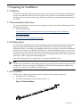
• 18 releasable cable ties shown in Figure 1-2.
Figure 1-2 Releasable Cable Tie
• The fasteners specified in Table 1-1.
Table 1-1 Fasteners
DescriptionTorqueFormatSizeQuantity
Cage nut for M6 screw.N/ASquare nutM6 cage nuts2
Machine screw. For use with M6 cage nut.25-30 in/lbPosidriveM6 x 16 mm
pan head screws
2
To prevent screws from becoming loose because of vibration, HP recommends that you use
an adjustable torque drive, set to the torque specifications given in Table 1-1. Contact your
HP sales representative if any parts are missing.
1.5 Required Resources
To install the HP cable management kit, you require the following resources:
• Tools:
— Screwdriver, #2 (medium) Phillips
— Cage-nut insertion tool (shipped with the rack) or a flat-headed screwdriver
— Marker pen or masking tape
— Diagonal cutting pliers
• Resources: Cables of the type used by the InfiniBand switch.
1.6 Prerequisites
Before you begin to mount the bracket:
• Follow the cable-handling precautions for InfiniBand cables. For more information, see the
HP Cluster Platform InfiniBand Interconnect Installation and User's Guide at:
http://www.docs.hp.com/en/highperfcomp.html
• Obtain the set of cabling tables required for your solution (if applicable).
• Read the hardware installation guide for the InfiniBand switch you are installing.
6 Preparing for Installation

2 Installing the Cable Management Bracket
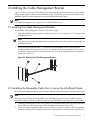
Figure 2-1 shows the correct orientation of the cable management bracket that you must install
before connecting the cables to the InfiniBand switch. The bracket provides strain relief for the
InfiniBand ports, and maintains the correct minimum cable bend radius.
Note:
One cable management kit is required for each InfiniBand switch.
2.1 Installing the Cable Management Bracket
To install the cable management bracket, follow these steps:
1. Align the cable management bracket (callout 2 in Figure 2-1) in the same “U” location as the
InfiniBand switch.
Note:
The location of the cable management bracket depends on the rack position occupied by the
InfiniBand switch.
2. Using the top hole in the same “U” location as the InfiniBand switch, fasten the cable
management bracket (callout 2 in Figure 2-1) to the rear rack columns (callout 1 in Figure 2-1)
by using two M6 pan-head screws (callout 3 in Figure 2-1) and tighten them to the specified
torque (see Table 1-1).
Figure 2-1 Mounting the Cable Management Bracket
1
2
3
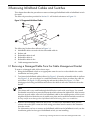
2.2 Installing the Releasable Cable Ties to Secure the InfiniBand Cables
To install the InfiniBand cables and secure them with the releasable cable ties, follow these steps:
Note:
For instructions on how to install cables in the InfiniBand switch or remove cables from the
InfiniBand switch, read the installation guide for the InfiniBand switch type that you installed.
1. Looking in from the rear of the rack, install one InfiniBand cable in the top left port and the
other cable in the bottom left port of the InfiniBand switch (see Figure 2-2).
2. Secure two of the InfiniBand cables at a time (callout 3 in Figure 2-2) to the cable management
bracket by sliding the releasable cable tie down through the second slot from the left on the
2.1 Installing the Cable Management Bracket 7

cable management bracket, go around the bottom cable, and then back up through the first
slot in the cable management bracket.
3. Put the releasable cable tie end through the buckle and secure the two InfiniBand cables
firmly.
Caution:
Only hand-tighten the releasable cable tie to prevent damage to the InfiniBand cables.
4. Leave approximately 3/8 inch to 1/2 inch coming out of the releasable cable tie buckle and
clip the excess. Use one of the clipped-off pieces of cable tie as a tightness gauge to ensure
that the InfiniBand cable moves freely, but is securely fastened in the releasable cable tie
loop.
5. Repeat steps 1 through 4 to install and secure the remaining InfiniBand cables to the cable
management bracket. Be sure to use the appropriate slots for each releasable cable tie.
6. Route the InfiniBand cables to the side of the rack and secure them either upward or
downward in the cable management plate. Be sure not to exceed the 4-inch minimum bend
radius for each InfiniBand cable as you route them in the rack.
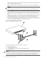
Figure 2-2 Installing the Releasable Cable Ties
1
2
3
4
The following list describes the callouts shown in Figure 2-2:
1. Left rear rack column
2. Cable management bracket
3. Two InfiniBand cables secured with one releasable cable tie
4. InfiniBand switch
Caution:
The releasable cable tie should only be tightened by hand. Do not use a cable tie installation tool
and do not over tighten the releasable cable tie or it might damage the InfiniBand cable.
8 Installing the Cable Management Bracket

3 Removing InfiniBand Cables and Switches
This chapter describes the procedure to remove a damaged InfiniBand cable or InfiniBand switch
for repair.
The removal procedure provided in Section 3.1 will include references to Figure 3-1.
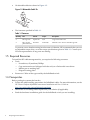
Figure 3-1 Supported InfiniBand Cables
2
3
4
5
6
1
The following list describes callouts in Figure 3-1:
1. InfiniBand cables secured with the releasable cable tie
2. Release tab
3. Releasable cable tie tail
4. Releasable cable tie
5. Releasable cable tie slot
6. Cable management bracket
3.1 Removing a Damaged Cable From the Cable Management Bracket
To remove a damaged cable, follow these steps:
1. Bring the InfiniBand switch to an appropriate state for service as described in the switch
installation and user guide.
2. To release the InfiniBand cables (callout 1 in Figure 3-1) from the releasable cable tie (callout
4 in Figure 3-1), use your finger or a small flat-headed screw driver to release the cable tie
tail (callout 3 in Figure 3-1) by pressing the release tab (callout 2 in Figure 3-1). This
disengages the locking mechanism and allows the cable tie tail to be withdrawn from the
buckle.
Note:
The release tab is very small and might be difficult to reach with your finger. Use a small
flat-headed screwdriver to press the release tab which releases the cable tie tail. Also, because
there are several cables, removal of an InfiniBand cable in the middle portion of the switch
might be difficult without the use of needle nose pliers and a small flat-headed screwdriver.
Be very careful not to damage other InfiniBand cables while using pliers or a screwdriver.
3. Remove the InfiniBand cable from the switch. To remove the InfiniBand cable, pull the
release tab on the QSFP connector while using your other hand to remove the connector
from the switch.
For information on how to remove an InfiniBand cable from the InfiniBand switch, see the
installation guide for the type of InfiniBand switch you are installing.
3.1 Removing a Damaged Cable From the Cable Management Bracket 9

3.2 InfiniBand Switch Removal
To remove an InfiniBand switch, follow these steps:
1. Bring the InfiniBand switch to an appropriate state for service as described in the user guide
for the switch.
2. Remove all of the InfiniBand cables from the InfiniBand switch, but leave them secured in
the cable management bracket.
3. Remove the cable management bracket from the mounting rails.
4. Leave the cables secured in the cable management bracket and carefully set the bracket
aside.
Caution:
Do not bend the InfiniBand cables more than the 4-inch minimum bend radius.
10 Removing InfiniBand Cables and Switches

11

*574412-doc*
Printed in the US
-
 1
1
-
 2
2
-
 3
3
-
 4
4
-
 5
5
-
 6
6
-
 7
7
-
 8
8
-
 9
9
-
 10
10
-
 11
11
-
 12
12


Ask a question and I''ll find the answer in the document
Finding information in a document is now easier with AI
Other documents
-
 12Volt 12V6CF User manual
-
Mellanox Technologies VLT-30111 Installation guide
-
-
-
-
-
Mellanox Technologies MCX455A-FCAT User manual
-
-
Mellanox Technologies IS5030Q-2BRC User manual
-
