Page is loading ...

Document Number 624000 Rev 004
FluidVision
®
4000
Flow, Temperature & Pressure
Measuring Instruments
Installation & Operating Instructions
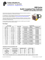
This document provides basic information describing the plumbing and electrical connections to install and make
operational your new FluidVision 4000 instrument.
A comprehensive Technical Reference Manual for these devices is available on the Proteus Industries website at
http://www.proteusind.com/4000/4000TRM.pdf. The manual contains detailed instructions for selecting output
formats and trip points for flow, temperature and pressure, technical descriptions, performance specifications and
mounting information, maintenance instructions and other valuable information.
Dimensional drawings and product warranty information can be viewed at http://www.proteusind.com.
Important Safety Information
NOTE and CAUTION statements are used throughout these instructions to highlight important operational and safety
information.
NOTE statements provide details that are important to the successful understanding and application of
the system.
CAUTION statements identify conditions or practices that could result in damage to the equipment or
other property.
WARNING statements identify conditions or practices that could result in personal injury or loss of life.
Taking proper precautions to avoid damage to your instrument’s sensors during installation helps ensure consistent,
error-free installations, which lowers costs and assists on-time completion of your work.
The CAUTION statements inserted in these instructions provide an alert to installers and operators to take sensible
steps to allow the instrument’s sensors to operate correctly the first time and every time.
NOTE
Installation of this product should be performed by qualified service personnel.
Proteus Industries Inc.

Document Number 624000 Rev 004
NOTE
Flow, temperature and pressure limits for all FluidVision 4000 instruments are provided in the
FluidVision 4000 Technical Reference Manual.
WARNING!
Do NOT exceed the temperature limit of the flow sensor body or faceplate material.
OPERATION ABOVE THE RATED TEMPERATURE CAN CAUSE FAILURE AND CREATE A
HAZARD TO OPERATORS AND EQUIPMENT!
WARNING!
Do NOT exceed the pressure limit of the flow sensor body or faceplate material.
OPERATION ABOVE THE RATED PRESSURE CAN CAUSE FAILURE AND CREATE A
HAZARD TO OPERATORS AND EQUIPMENT!
1. Make Liquid Connections
a. Identify the type and size of connections from the Model Number table below.
Flow Ranges Part Numbers
GPM LPM
Connection
Brass Stainless Steel Polypropylene
0.06 – 0.6 0.2 – 2.2 ¼” FNPT 04004BN06-XXX 04004SN06-XXX 04004PN06-XXX
0.1 – 1.4 0.4 – 5.3 ¼” FNPT 04004BN1-XXX 04004SN1-XXX 04004PN1-XXX
0.2 – 2.5 0.8 – 9.5 ¼” FNPT 04004BN2-XXX 04004SN2-XXX 04004PN2-XXX
0.2 – 2.5 0.8 – 9.5
9
/
16
-18 SAE 04006SA2-XXX
0.3 – 4.5 1.1 – 17 ¼” FNPT 04004BN4-XXX 04004SN4-XXX 04004PN4-XXX
0.3 – 4.5 1.1 – 17
9
/
16
-18 SAE 04006SA4-XXX
0.6 – 9.0 2.2 – 34 ⅜" FNPT 04006BN9-XXX 04006SN9-XXX
0.6 – 10 2.2 – 38 ⅜" FNPT 04006PN10-XXX
0.8 – 10 3.0 – 38 ¾ -16 SAE 04008SA10-XXX
1.0 – 14 3.8 – 53 ½" FNPT 04008BN14-XXX 04008SN14-XXX 04008PN14-XXX
1.2 – 16 4.5 – 60 ¾" FNPT 04012BN16-XXX 04012SN16-XXX
1.2 – 16 4.5 – 60 1
1
/
16
-12 SAE 04012SA16-XXX
1.5 – 19 5.7 – 72 ¾" FNPT 04012PN19-XXX
3.0 – 40 11 – 151 ¾" FNPT 04012BN40-XXX 04012SN40-XXX
4.0 – 40 15 – 151 1" FNPT 04016BN40-XXX 04016SN40-XXX
4.0 – 40 15 – 151 1
5
/
16
-12 SAE 04016SA40-XXX
4.0 – 50 15 – 189 1" FNPT 04016PN50-XXX
5.0 – 60 19 – 227 1" FNPT 04016BN60-XXX 04016SN60-XXX
CAUTION!
Do NOT exceed the maximum rated flow rate of your instrument.
EXTENDED USE ABOVE THE RATED MAXIMUM FLOW RATE OF THE INSTRUMENT WILL
REDUCE ITS USEABLE LIFE!

Document Number 624000 Rev 004
b. Make connections to pipe or other fittings as required.
CAUTION!
Do NOT use anaerobic pipe sealants such as Loctite
®
or Swak
®
brand sealants with
FluidVision 4000 instruments fitted with polysulfone or polycarbonate faceplates.
The aggressive chemical nature of solvent vapors arising from these materials can cause
cracking of the polysulfone or polycarbonate faceplates.
Use Teflon
®
(PTFE) tape or PTFE-based liquid sealants to provide leak-tight and lubricated
junctions at all connection points.
CAUTION!
Do NOT install metal fittings into polypropylene bodies.
Over-tightening of metal fittings in polypropylene bodies can permanently damage the NPT
threads and prevent the creation of a leak-free connection.
c. Turn on your liquid flow slowly and check for leaks at the connections. Tighten connections as required to
eliminate leaks.
2. Make Electrical Connections
a. Locate the 24 VDC power source and turn it OFF.
b. Connect and secure the provided cable to the multi-pin connector on the instrument.
c. Connect the instrument to your system controller s shown in the table below.
CAUTION!
Do NOT connect the BROWN wire to power until all other connections have been made and
proven.
NOTE
Unless otherwise specified, your FluidVision 4000 instrument has been shipped with outputs of 0–5
VDC for flow, temperature and pressure. Refer to the FluidVision 4000 Technical Reference
Manual for information on how to select 0–10 VDC or 4–20 mA output formats.
Function Pin # Color
Common/Ground 1 White
24 VDC Supply Voltage 2 Brown
Relay – NO (Normally Open) 3 Green
Relay – Common 4 Yellow
Relay – NC (Normally Closed) 5 Grey
Flow Output 6 Pink
Temperature Output 7 Blue
Pressure Output 8 Red

Document Number 624000 Rev 004
d. Verify the correctness of your wiring.
e. Connect the BROWN wire to the +24 VDC power source and turn 24 VDC power ON.
Result: LED indicating lamps will be illuminated. The color of the LED will be green, amber or red
depending on the measured value of the parameter and the selected trip point value.
If installed, the digital display will show the present measured value of each parameter.
A measurable voltage should be present for each installed parameter.
3. Functional Testing
If possible, vary the flow rate, temperature and pressure of your system.
If installed, the digital display will indicate an immediate change in the measured value.
The output voltage for each parameter should increase or decrease as the value of the parameter
changes.
4. Identify Trip Points
NOTE
If a calibration label on the instrument indicates a factory-set trip point, no adjustment is needed.
If not otherwise specified, trip points for flow, temperature and pressure have been pre-set during calibration to the
following values:
Parameter Switch Setting Range Trip Point Value
Flow 3 Various Approximately 0.25 x the maximum flow rating
Temperature C 0 – 75°C Approximately 55°C
Temperature C 0 – 100°C Approximately 75°C
Pressure C 0 – 70 psi Approximately 55 psi
Pressure C 0 – 100 psi Approximately 75 psi
Pressure C 0 – 250 psi Approximately 190 psi
NOTE
Refer to the FluidVision 4000 Technical Reference Manual for detailed instructions on the selection
and adjustment of trip points for flow, temperature and pressure.
Proteus Industries Inc
.
340 Pioneer Way, Mountain View, CA 94041
Tel: (650) 964-4163 Fax: (650) 965-0304
www.proteusind.com sales@proteusind.com
Information in this document was correct at the time of
printing; however, specifications are subject to change as
Proteus Industries’ continuous improvement processes
establish new capabilities.
© Proteus Industries Inc. August 2007
/


