Page is loading ...

Page 1 of 40
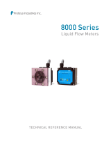
FluidVision
®
4000
Flow, Temperature & Pressure
Measuring Instruments
Technical Reference Manual
Contents
Section Description Page
1 Introduction & How They Work 3
2 Specifications & Performance 7
3 Installing FluidVision 4000 Instruments 10
4 Electrical Installation
4.1 Selecting Output Formats & Ranges
4.2 Selecting Display Units
4.3 Electrical Connections
16
16
22
26
5 Selecting Trip Points 27
6 Cleaning & Maintenance 34
7 Calibration & Recalibration 40
8 Flow, Temperature & Pressure Response Curves 41
9 Dimensions and Outline Drawings 41

Page 2 of 40
Important Safety Information
NOTE and CAUTION statements are used throughout this manual to highlight important operational and
safety information.
L
NOTE statements provide details that are important to the successful understanding and
application of the system.
CAUTION statements identify conditions or practices that could result in damage to the
equipment or other property.
WARNING statements identify conditions or practices that could result in personal injury
or loss of life.
Taking proper precautions to avoid damage to your instrument’s sensors during installation helps ensure
consistent, error-free installations, which lowers costs and assists on-time completion of your work.
The CAUTION statements inserted in these instructions provide an alert to installers and operators to
take sensible steps to allow the instrument’s sensors to operate correctly the first time and every time.
Technical Support
For technical or applications assistance, contact:
Proteus Industries Inc.
340 Pioneer Way
Mountain View, CA 94041
Phone: (650) 964-4163
Fax: (650) 965-0304
E-mail: tech@proteusind.com
NOTE
L
Product warranty does NOT cover the repair of installation errors
Proteus FluidVision 4000 instruments are manufactured by ISO 9001-registered
processes and are warranted to be free from material and workmanship defects. The full
text of the warranty is available on the Proteus Industries website at
www.proteusind.com/warranty.
T
he costs of cleaning flow sensors, recalibration or repair of mechanical damage incurred
during installation of the product are NOT covered by the warranty.
A Purchase Order will be required to allow the recovery of such service costs.
CAUTION!
This product contains lead solder. Disposal of this product should be carried out
in compliance with local regulations.

Page 3 of 40
Section 1: Introduction & How They Work
FluidVision 4000 instruments measure the flow rate, temperature and pressure of water, water/glycol
mixtures, Galden®, Fluorinert® and other liquids. All sensors are combined in one unit for an easy and
compact installation.
FluidVision 4000 sensors provide accurate and precise measurement of these parameters, providing 0–5
VDC, 0–10 VDC or 4–20 mA outputs. Trip points for all three parameters are individually selectable and
can be linked to a switching relay.
This manual provides information to help you install FluidVision 4000 instruments into your fluid system.
NOTE
L
Installation of this product should be performed by qualified service personnel.
How Do They Work?
Flow Rate
A rotor spins when liquid moves through the flow sensor
body. Magnets in the rotor switch a Hall-effect sensor
mounted in the sensor body.
The flow range of the sensor is determined by the diameter
of the precisely-formed orifice. The maximum range is
selected to be the flow at which the rotor spins at a rate of
40 revolutions per second or that flow at which pressure
drop across the sensor is 10 psi.
The frequency of the pulse train from the Hall-effect sensor
is converted to a flow rate by calibration against traceable
flow standards. The flow output is made available as 0–5
VDC, 0–10 VDC or 4–20 mA signals.
The resulting outputs have excellent linearity. The user-adjusted flow trip point is linked to a relay output.
The measured flow rate can be visually displayed on an optional LCD display. A bright tri-color LED
indicates flow status.
Flow range data for FluidVision 4000 instruments are listed in Section 2 of this manual. Information on
how to obtain flow response curves is provided in Section 8.
Hall Effect Senso
r
Rotor with magnets

Page 4 of 40
Temperature
A semiconductor transducer embedded in a stainless steel housing senses the temperature of the flowing
liquid over the range of -40 to 125°C. The device produces an output current proportional to absolute
temperature, producing 1 µA/°K. This current is converted to produce an output voltage of 1 mV/°K.
• The temperature range of FluidVision 4000 instruments depends on the materials from which the flow
sensor and faceplate are formed.
Temperature Range (°C)
-40 -30 -20 -10 0 10 20 30 40 50 60 70 80 90 100 110 120 130
Polypropylene bodies with polysulfone or polycarbonate faceplates
Brass & stainless steel bodies with polysulfone or polycarbonate faceplates
Brass & stainless steel bodies with brass or stainless steel faceplates
For applications in which temperatures are always above the freezing point of water, an output voltage of
0V represents 0°C
. For applications in which temperatures can drop below the freezing point of water, an
output voltage of 0V represents -50°C.
The selected output range is made available as 0–5 VDC, 0–10 VDC or 4–20 mA signals.
The user-adjusted temperature trip point is linked to a relay output. The measured temperature can be
visually displayed on an optional LCD display.
A bright tri-color LED indicates temperature status.
Information on how to obtain temperature response curves is provided in Section 8 of this manual.
Pressure
A temperature-compensated device with an operating range of > 250 psi measures pressure.
The pressure range over which the device is calibrated is determined by the materials from which the flow
sensor is formed. Pressure response is calibrated during final testing against traceable pressure
standards.
Pressure Range (psi)
0 20 40 60 80 100 120 140 160 180 200 220 240 260
Polypropylene bodies with polysulfone
or polycarbonate faceplates
Brass & stainless steel bodies with polysulfone
or polycarbonate faceplates
Brass & stainless steel bodies with brass or stainless steel faceplates
Pressure outputs are made available as 0–5 VDC, 0–10 VDC or 4–20 mA signals.
The user-adjusted pressure trip point is linked to a relay output. The measured pressure can be visually
displayed on an optional LCD display. A bright tri-color LED indicates pressure status.
Information on how to obtain pressure response curves is provided in Section 8 of this manual.

Page 5 of 40
LED Status Indicators
Bright tri-color LEDs indicate the statuses of flow, temperature and pressure. Each sensor’s trip point
comparator circuit directly controls the color of the corresponding LED.
The LEDs function as traffic lights to provide an instant indication of the state of each monitored
parameter.
A GREEN LED indicates the sensor is in its normal state.
An AMBER LED provides a CAUTION warning – the sensor is in its normal state, but the measured value
is within 15% of the selected trip point value.
A RED LED indicates the sensor is in its alarm state.
O
ver-Range Warning Indicator
To prevent a FluidVision 4000 instrument from being continually operated in a manner that could become
unsafe or induce excessive wear, the instrument is fitted with an over-range warning circuit that senses
when flow, temperature or pressure reaches a level more than 8% above the recommended operating
limit.
When an over-range state is detected, the parameter output is switched to 0 VDC or 4 mA, signaling an
alarm condition to the controller.
The LED Status Indicator will be GREEN.
The LCD display, if installed, will indicate the actual measured value of the over-ranged parameter.
Relay Output
A relay allows the user to set alarm levels for low flow rate, high temperature and high pressure.
The state of a SPDT 1A 48 VDC relay is controlled by the trip point status of all installed sensors. A
system controller or PLC can monitor the relay’s state, and the relay may be connected to other control
relays to provide redundant interlock capability.
Pressure is > trip point pressure RED
Pressure is 0.85 to 1.0x trip point pressure
AMBE
R
Pressure is < 0.85x trip point pressure
GREEN
PRESSURE LED STATUS
Temperature is > trip point temperature
RED
Temperature is 0.85 to 1.0x trip point temperature
AMBE
R
Temperature is < 0.85x trip point temperature
GREEN
TEMPERATURE LED STATUS
Flow is < trip point flow
RED
Flow is 1.0 to 1.15x trip point flow
AMBE
R
Flow is > 1.15x trip point flow
GREEN
FLOW LED STATUS

Page 6 of 40
The relay is in its alarm state if it is not energized, the same condition as when there is no power applied to
it.
Relay State Current in Coil NO (Normally Open) Contact NC (Normally Closed) Contact
Energized
Current flowing
Connected to
RELAY COM contact
OPEN
Normal
NO current flowing
OPEN
Connected to
RELAY COM contact
• The control relay can be in the energized state if and only if ALL installed sensors are measuring non-
alarm conditions.
• The relay will be in its NORMAL state if ONE OR MORE of the installed sensors measures an alarm
condition.
LCD Display
An optional digital display unit provides continuous display of flow rate
on the top line and either temperature or pressure on a second line if
one other sensor is installed.
If both temperature and pressure sensors are installed, the values of
each of these parameters is alternately displayed on the second line
along with the unit of measure for each parameter.
Certifications
FluidVision 4000 instruments are CE marked for compliance with the EU Directive 89/336/EEC for
electromagnetic compatibility.

Page 7 of 40
Section 2: Specifications & Performance
The most current information on the performance capability of these sensors is available on the Proteus
Industries website at www.proteusind.com.
Flow Ranges Part Numbers
GPM LPM
Connection
Brass Stainless Steel Polypropylene
0.06 – 0.6 0.2 – 2.2 ¼” FNPT 04004BN06-XXX 04004SN06-XXX 04004PN06-XXX
0.1 – 1.4 0.4 – 5.3 ¼” FNPT 04004BN1-XXX 04004SN1-XXX 04004PN1-XXX
0.2 – 2.5 0.8 – 9.5 ¼” FNPT 04004BN2-XXX 04004SN2-XXX 04004PN2-XXX
0.2 – 2.5 0.8 – 9.5
9
⁄
16
-18 SAE 04006SA2-XXX
0.3 – 4.5 1.1 – 17 ¼” FNPT 04004BN4-XXX 04004SN4-XXX 04004PN4-XXX
0.3 – 4.5 1.1 – 17
9
⁄
16
-18 SAE 04006SA4-XXX
0.6 – 9.0 2.2 – 34 ⅜" FNPT 04006BN9-XXX 04006SN9-XXX
0.6 – 10 2.2 – 38 ⅜" FNPT 04006PN10-XXX
0.8 – 10 3.0 – 38 ¾ -16 SAE 04008SA10-XXX
1.0 – 14 3.8 – 53 ½" FNPT 04008BN14-XXX 04008SN14-XXX 04008PN14-XXX
1.2 – 16 4.5 – 60 ¾" FNPT 04012BN16-XXX 04012SN16-XXX
1.2 – 16 4.5 – 60 1
1
⁄
16
-12 SAE 04012SA16-XXX
1.5 – 19 5.7 – 72 ¾" FNPT 04012PN19-XXX
3.0 – 40 11 – 151 ¾" FNPT 04012BN40-XXX 04012SN40-XXX
4.0 – 40 15 – 151 1" FNPT 04016BN40-XXX 04016SN40-XXX
4.0 – 40 15 – 151 1
5
⁄
16
-12 SAE 04016SA40-XXX
4.0 – 50 15 – 189 1" FNPT 04016PN50-XXX
5.0 – 60 19 – 227 1" FNPT 04016BN60-XXX 04016SN60-XXX
Temperature & Pressure Operating Limits
Temperature Range Pressure Range Flow Sensor
Material
Faceplate
Material
°C °F psi kPA
Brass Clear Polysulfone -40 to 100 -40 to 212 100 690
Brass Brass -40 to 125 -40 to 257 250 1723
04016BXX Clear Polycarbonate -40 to 100 -40 to 212 100 690
Stainless Steel Clear Polysulfone -40 to 100 -40 to 212 100 690
Stainless Steel Stainless Steel -40 to 125 -40 to 257 250 1723
04016SXX Clear Polycarbonate -40 to 100 -40 to 212 100 690
Polypropylene Clear Polysulfone -40 to 70 -40 to 158 75 517
04016PXX Clear Polycarbonate -40 to 70 -40 to 158 75 517
Notes:
1. Electronics are rated for operation to 85°C (185
o
F). At higher temperatures, the electronics unit must be
mounted remotely from the flow, temperature and pressure sensor unit. Contact Proteus Technical
Support for additional information.
2. The compensated calibration range of the pressure sensor in standard FluidVision 4000 Series
instruments is 0°C to 82°C (32°F to 180°F). Custom calibration for higher or lower temperatures is
available. Contact Proteus Technical Support for information.
3. If operated below 0°C, ice will normally form on the flow sensor and electronics unit. Contact Proteus
Applications Support for information on insulation kits to restrict ice build-up.
4. The kinematic viscosity of the circulating liquid must be sufficiently low to allow the rotor to spin freely.
Contact Proteus Applications Support for information on system performance with specialized materials for
use at high- and low-temperature extremes.

Page 8 of 40
Wetted Materials
Flow Sensor Body Brass, 316 Stainless Steel or Polypropylene
Faceplates Clear polysulfone for 04004XXX to 04012XXX instruments; polycarbonate for
04016X instruments.
Brass faceplates are optionally a
vailable for 04004BXXX to 04012BXXX
instruments.
Stainless steel faceplates are optionally available for 04004SXXX to
04012SXXX instruments.
Sealing O-Ring Viton® standard; Buna-N, EPDF and silicone rubber are optionally available.
Rotor PPS standard; Kynar® and Nylon 66 are optionally available.
Rotor Shaft 316 stainless steel standard; alumina and sapphire are optionally available.
Flow Measurement Capability
Voltage Output 0–5 VDC, 0–10 VDC or 4–20 mA outputs can be operator-selected for each
measured parameter.
Accuracy Device accuracy is the measurement capability of the sensor. The following
statement should be read in conjunction with the Calibration information below:
Improved accuracy and linearity performance over smaller flow ranges can be
achieved by specialized NIST-traceable calibration procedures.
Linearity Flow: ± 1.5% of full scale
Temperature: ± 1°C (0–100°C)
Pressure: ± 1 psi (0–100 psi)
± 3 psi (0–250 psi)
Repeatability Flow: ± 0.5% of full scale
Temperature: ± 0.3°C (0–100°C)
Calibration A statement of Conformance is provided with each instrument. Flow and
pressure calibrations are performed with water at ambient temperature. Our
calibration accuracy is maintained by statistical comparison with NIST-
traceable standards.
Flow Measurement Capability
Measurement capability of the FluidVision 4000 is stated on a Certificate of Conformance delivered with
each instrument. A Certificate of Calibration providing improved accuracy at a single calibration point is
available at additional cost.
Accuracy
± 3% of full scale is stated on a Certificate of Conformance. Flow
response is adjusted at high- and low-reference flows selected on
production standards whose response is controlled to ± 1% of their
range.
Linearity
± 1.5% of full scale from 0.1 to
1.0x the flow range.
Accuracy of ± 1% of reading can be stated for a single flow point on a
Calibration Certificate. This calibration adjustment is referenced to a
flow standard whose response is controlled to ± 0.5% of the selected
flow point.
Repeatability
± 1% of full scale from 0.1 to
1.0x the flow range.

Page 9 of 40
Temperature Measurement Capability
Accuracy
± 3% of full scale is stated on a Certificate of Conformance.
Temperature response is adjusted at high and low reference
temperatures selected on production standards whose response is
controlled to ± 1% of their value.
Linearity
± 1% of full scale from 0.1 to
1.0x the temperature range
Accuracy of ± 1% of reading can be stated for a single temperature
point on a Calibration Certificate. This calibration adjustment is
referenced to a temperature standard whose response is controlled to
± 0.2% of the selected value.
Repeatability
± 0.5% of full scale from 0.1 to
1.0x the temperature range
Pressure Measurement Capability
Accuracy
± 3% of full scale is stated on a Certificate of Conformance. Pressure
response is adjusted at high and low reference pressures selected on
production standards whose response is controlled to ± 0.5% of their
value.
Linearity
± 1% of full scale from 0.1 to
1.0x the pressure range
Accuracy of ± 1% of reading can be stated for a single pressure on a
Calibration Certificate. This calibration adjustment is referenced to a
pressure standard whose response is controlled to ± 0.2% of the
selected value.
Repeatability
± 0.5% of full scale from 0.1 to
1.0x the pressure range
Calibration and Measurement Uncertainty
Accuracy specifications for the FluidVision 4000 instruments INCLUDE the uncertainty of our calibration
process. This inclusion results in a higher number than would be stated for the uncertainty ascribed to
the reference standards.
Switch Performance
Trip Point Selection A 16-position rotary switch divides the flow, temperature and pressure ranges
into 17 equal steps.
A single-turn potentiometer provides fine adjustment of parameter values:
When the potentiometer is set to the 12 o’clock position, the trip point values
are as indicated in the Range and Trip Point Tables on pages 29 (Flow), 31
(Temperature) and 33 (Pressure) of this manual.
When the potentiometer is turned clockwise to its maximum position (5
o’clock), the trip point is the mid-point value plus 1 step.
When the potentiometer is turned counterclockwise to its minimum position
(7 o’clock), the trip point is the mid-point value minus ⅓ step.
Step size can be determined from the Range and Trip Point Tables.
Switch Type Relay Closure, Normally Open and Normally Closed contacts are provided.
Relay Rating SPDT 1 A at 48 VDC
Electrical
Power Requirements 24 ± 10% VDC, 200 mA
Over-Voltage Protection A thermal resettable fuse turns unit OFF if input voltage exceeds 29 VDC.
Electrical Connection 2 m 8/24 AWG PVC insulated cable, rated 1.5 A at 36 VDC

Page 10 of 40
Section 3: Installing FluidVision 4000 Instruments
Physical Installation
Selecting Instrument Location
When selecting the location and method of mounting of the FluidVision 4000 instruments consider the
following factors:
• Size of instrument – Information on how to obtain product dimensions is provided in Section 9 of this
manual.
• Proximity to unprotected electronics – It is undesirable to mount any plumbing connections directly
over electronic controls or other unprotected instrumentation because of the potential for leaks or
condensation to cause damage. While the NEMA 4 packaging preserves the integrity of your
FluidVision 4000 instrument, it cannot prevent leakage or condensation from damaging other devices!
• Weight of instrument – The weight of the instrument may to be too high to allow the unit to be reliably
mounted on rigid pipe or by panel-mounting using the faceplate-securing screws.
• Access to cables – Information on how to obtain outline drawings is provided in Section 9 of this
manual. Check these for the location of the electrical connections.
• Visibility of digital display – If your FluidVision 4000 instrument is fitted with an optional digital display,
the unit should be situated so that the displayed information is viewable by an operator in the
available ambient light.
• Orientation
o Ideally, the unit should be mounted with the faceplate of the flow sensor in a vertical plane.
o Mounting the unit with the flow path horizontal and uppermost will assist in removing entrained air
from the flow sensor.
o If mounting with the flow path vertical, ensure that the flow direction is upwards to eliminate errors
arising from vortex formation or other effects from an incompletely-filled pipe.
• Flow Direction – The flow direction through 04004PN06-XXX instruments MUST be from Port A to
Port B.
All other FluidVision 4000 instruments can be installed with liquid entering the flow sensor through
either port.
• Proximity to other devices – The flow response of FluidVision 4000 instruments and thus their
calibration may be affected by the form of any device attached to the inlet connection as well as on
the form of nearby upstream devices.
Elbows, T-pieces, valves and filters located immediately upstream from the flow sensor can introduce
swirling motion to the liquid flow, reducing the linear velocity of the flow stream.
We recommend that a straight run of pipe of more than 10x pipe ID be used between the flow sensor
and any upstream devices to minimize these effects.
Appropriate calibration procedures must be used to provide an accurate flow measurement with
elbows or T-pieces that must be attached directly to the inlet connection. Contact Proteus Technical
Support for assistance.
FluidVision 4000 instruments are typically unaffected by the form or proximity of downstream devices.

Page 11 of 40
• ID of connection or pipe
The flow response of a FluidVision 4000 instrument, and thus its calibration, may be dependent on
the internal diameter (ID) of the incoming pipe or the ID of a connecting device.
NOTE
L
If the ID of your pipe or tube fitting where it connects to the inlet port is LESS than the
Orifice ID listed in Tables 1 and 2 below, calibration values may be invalid.
Appropriate calibration procedures can be applied to allow the FluidVision 4000 instruments to be
used with pipes and connections with IDs smaller than those shown in Tables 1 and 2 below. Contact
Proteus Technical Support for assistance.
Flow Ranges Orifice ID Part Numbers
GPM LPM
Connection
inch cm Stainless Steel Brass
0.06 – 0.6 0.2 – 2.2 ¼” FNPT 0.063 0.16 04004SN06-XXX 04004BN06-XXX
0.1 – 1.4 0.4 – 5.3 ¼” FNPT 0.118 0.30 04004SN1-XXX 04004BN1-XXX
0.2 – 2.5 0.8 – 9.5 ¼” FNPT 0.188 0.48 04004SN2-XXX 04004BN2-XXX
0.2 – 2.5 0.8 – 9.5
9
⁄
16
-18 SAE 0.188 0.48 04006SA2-XXX
0.3 – 4.5 1.1 – 17 ¼” FNPT 0.27 0.68 04004SN4-XXX 04004BN4-XXX
0.3 – 4.5 1.1 – 17
9
⁄
16
-18 SAE 0.27 0.68 04006SA4-XXX
0.6 – 9.0 2.2 – 34 ⅜" FNPT 0.37 0.94 04006SN9-XXX 04006BN9-XXX
0.8 – 10 3 – 38 ¾ -16 SAE 0.40 1.02 04008SA10-XXX
1.0 – 14 3.8 – 53 ½" FNPT 0.46 1.17 04008SN14-XXX 04008BN14-XXX
1.2 – 16 4.5 – 60 ¾" FNPT 0.61 1.55 04012SN16-XXX 04012BN16-XXX
1.2 – 16 4.5 – 60 1
1
⁄
16
-12 SAE 0.61 1.55 04012SA16-XXX
3 – 40 11 – 150 ¾" FNPT 0.80 2.03 04012SN40-XXX 04012BN40-XXX
4 – 40 15 – 150 1" FNPT 0.87 2.21 04016SN40-XXX 04016BN40-XXX
4 – 40 15 – 150 1
5
⁄
16
-12 SAE 0.80 2.03 04016SA40-XXX
5 – 60 18 – 225 1" FNPT 1.00 2.54 04016SN60-XXX 04016BN60-XXX
Table 1: Flow Ranges, Part Numbers and Orifice IDs for Brass & Stainless Steel instruments.
Flow Ranges Orifice ID Part Numbers
GPM LPM
Connection
inch cm Polypropylene
0.06 – 0.6 0.2 – 2.2 ¼” FNPT 0.063 0.16 04004PN06-XXX
0.1 – 1.4 0.4 – 5.3 ¼” FNPT 0.118 0.30 04004PN1-XXX
0.2 – 2.5 0.8 – 9.5 ¼” FNPT 0.188 0.48 04004PN2-XXX
0.3 – 4.5 1.1 – 17 ¼” FNPT 0.27 0.48 04004PN4-XXX
0.6 – 10 2.2 – 38 ⅜" FNPT 0.37 0.94 04006PN10-XXX
1.0 – 14 3.8 – 53 ½" FNPT 0.46 1.17 04008PN14-XXX
1.5 – 19 5.7 – 72 ¾" FNPT 0.61 1.55 04012PN19-XXX
4.0 – 50 15 – 189 1" FNPT 0.87 2.21 04016PN50-XXX
Table 2: Flow Ranges, Part Numbers and Orifice IDs for Polypropylene Instruments.

Page 12 of 40
• Material compatibility
It is recommended that connections be made with material similar to that of the flow sensor body to
avoid potential corrosion effects.
CAUTION!
Over-tightening of metal fittings in polypropylene bodies can permanently damage
the NPT threads and prevent the creation of a leak-free connection.
• Filtering
Your circulating fluid may contain particles. While not essential to the operation of the flow sensor, it
is good practice to filter your fluid. A 100-micron filter is often used to remove rust and other particles
from the fluid. This can increase the lifetime of pumps and other fluid system components as well as
reduce wear in the sensor.
If fitted with a clear polysulfone or polycarbonate faceplate, your FluidVision 4000 instrument sensor
may provide the only view you have of the cleanliness of your circulating fluid!
Protection of the proper operation of your FluidVision 4000 instruments sensor also provides an
additional level of protection to the more expensive equipment being cooled!
• Low liquid temperature
Ice will form on the FluidVision 4000 instrument when liquid temperature is below 0°C. The NEMA 4
casing of the instrument will prevent moisture from entering the unit.
Ice will prevent observation of the digital display. Remote mounting of the electronics unit with its
digital display can provide a solution. Contact Proteus Technical Support for information.
• High liquid temperature
If liquid temperature will exceed 85°C, the electronics must be located separate from the sensor unit.
Contact Proteus Technical Support for information.

Page 13 of 40
Making Plumbing Connections
CAUTION!
Before connecting your FluidVision 4000 instrument to your liquid supply line,
verify that the normal flow rates expected are within the operating range of the
sensor as listed in Tables 1 and 2.
EXTENDED USE ABOVE THE RATED MAXIMUM FLOW RATE OF THE
INSTRUMENT WILL REDUCE ITS USEABLE LIFE!
The FluidVision 4000 instrument will NOT provide an output signal for flow rates more than 1.08 x the
rated flow – see page 5 of this manual for details about the Over-Range Warning indicator.
WARNING!
Before connecting your FluidVision 4000 instrument to your liquid supply line,
verify that the system’s peak operating temperature will NOT exceed the
measurement range of the instrument.
OPERATION ABOVE THE RATED TEMPERATURE CAN CAUSE FAILURE AND
CREATE A HAZARD TO OPERATORS AND EQUIPMENT!
WARNING!
Before connecting your FluidVision 4000 instrument to your liquid supply line,
verify that the system’s peak operating pressure will NOT exceed the measurement
range of the instrument.
OPERATION ABOVE THE RATED PRESSURE CAN CAUSE FAILURE AND CREATE
A HAZARD TO OPERATORS AND EQUIPMENT!
CAUTION!
Do NOT use anaerobic pipe sealants such as Loctite
®
or Swak
®
brand sealants with
FluidVision 4000 instruments fitted with polysulfone or polycarbonate faceplates.
The aggressive chemical nature of solvent vapors arising from these materials can
cause cracking of the polysulfone or polycarbonate faceplates.
Use Teflon
®
(PTFE) tape or PTFE-based liquid sealants to provide leak-tight and
lubricated junctions at all connection points.
Real-Tuff
®
and Hercules
®
are two of many suitable brands of PTFE-based sealants.

Page 14 of 40
Making NPT pipe thread connections
Pipe threads sealed by metal-to-metal contact between male and female components are particularly
prone to the damaging effects of galling, which occurs when two surfaces move against each other under
pressure. When installing pipe threads, it is essential to use high-quality lubricating and sealing material.
• Use Teflon tape or a PTFE-based liquid sealant to provide lubrication for the junction and a leak-tight
connection at both the input and output connections.
• Do not over-tighten the connection. Refer to instructions for installation of the mating fittings for
information on torque requirements.
• Leak testing of all connections in your flow circuit is recommended. Pressurizing the system with air
and external testing with a dilute soap solution can help identify leaking connections.
• Plastic pipe or fitting should be used with polypropylene instruments. Improper connections of metal
pipe or fittings into polypropylene flow sensors can cause stripping of the polypropylene threads and
potentially split the flow sensor body.
Making SAE straight thread connections
With these connectors, an O-ring makes the seal while the threads hold the connecting assembly in
place. Straight thread connections should receive a small amount of high-pressure lubricant before
installation to prevent galling.
Non-adjustable fittings
1. Bring the non-adjustable fitting into firm
contact with the face of the port using a
wrench.
2. Check to be certain that the O-ring fits
easily into the non-threaded receiving
area of the port and is not pinched.
Adjustable fittings
1. Ensure that the locknut is positioned so
that the back-up washer is in contact
with the beginning of the threads
farthest from the end of the fitting.
2. Screw the fitting into the port until the
back-up washer contacts the sealing
face.
3. Check to be certain that the O-ring fits
easily into the non-threaded receiving
area of the port, and is not pinched or
damaged.
4. Unscrew the fitting a maximum of one
turn to position it in the desired direction.
5. Tighten the locknut firmly against the
back-up washer so that the fitting
assembly is held securely in place.

Page 15 of 40
Starting Up your FluidVision 4000 Instrument
1. Check for Leaks
• Turn ON the liquid supply to a low flow rate and check that ALL connections are watertight.
Make adjustments to pipes or fittings to ensure that there are no leaks from the connection ports.
• Turn ON the liquid supply to its full pressure rating and again check that there are no leaks from the
c
onnections ports.
2. Eliminate Entrained Air from the Flow Sensor
Air bubbles entrained between the rotor arms reduce resistance to rotation of the rotor and allow the rotor
to spin FASTER. Subsequently, the instrument will register a higher than actual flow rate until ALL air
bubbles have been eliminated from the flow sensor.
• The air bubbles may disperse out of the flow sensor over several hours of operation.
• In a closed-loop system the air will eventually accumulate in the highest space in the system.
P
rovision for collection and bleeding of the entrained air can be made during system design.
• The rate of dispersion is speeded by mounting the flow sensor so that the flow path is uppermost.
• Pulsing flow by rapidly increasing and decreasing flow through the system can assist by
ac
celerating the bubbles towards the exit port.

Page 16 of 40
Section 4: Electrical Installation
NOTE
L
Electrical installation should be performed by personnel familiar with the electrical circuit
and control functions of the system in which the FluidVision 4000 instrument is to be
installed.
CAUTION!
The electronics in a FluidVision 4000 instrument are sensitive to electrostatic
discharge (ESD). Proper ESD precautions should be taken when handing the
instrument’s electronic components.
Section 4.1: Selecting Output Formats & Ranges
The output formats and ranges for each of flow rate, temperature and pressure are switch-selectable.
NOTE
L
Unless otherwise specified on your Purchase Order, all FluidVision 4000 instruments are
shipped with 0–5 VDC output mode selected for all installed sensors.
To select an output mode of 0–10 VDC or 4–20 mA, proceed as follows:
1. Ensure that electrical power is OFF.
2. Remove the clear plastic window and its sealing gasket from the electronics unit.
2.1. With a Philips head screwdriver, remove and retain
the four (4) screws securing the window.
2.2. Carefully remove the window and the attached
digital display unit (if installed) to gain access to
the electronics.
2.3. Place the window and digital display so you can
see and adjust the switches located on
the edge of the electronic circuit boards.

Page 17 of 40
NOTE
L
If the switches in your FluidVision 4000 instrument do NOT look like those in the
photographs below, please contact Proteus Technical Support at (650) 964-4163 or
tech@proteusind.com t
o obtain instructions for selecting output flow, temperature and
pressure output ranges.
Flow Controls
Temperature Controls
Pressure Controls
Figure 1: Location of flow, temperature and pressure controls
3. Setting the FLOW output
3.1. Identify the FLOW electronics board from Figure 1.
3.2. With a fine flat-head screwdriver, move switches 1, 2 and 3 down to the OFF position.
NOTE
L
Do NOT change the positions of switches 4 through 8!
3.3. To select an output range of 0–5 VDC, move Switch 1 up to the ON position (default).

Page 18 of 40
3.4. To select an output range of 0–10 VDC, move Switch 2 up to the ON position.
3.5. To select an output range of 4–20 mA, move Switch 3 up to the ON position.
4. Setting the TEMPERATURE output
4.1. Identify the TEMPERATURE electronics board from Figure 1.
4.2. With a fine flat-head screwdriver, move switches 1, 2 and 3 down to the OFF position.
NOTE
L
Do NOT change the positions of switches 4 through 8!
4.3. To select an output range of 0–5 VDC, move Switch 1 up to the ON position (default).

Page 19 of 40
4.4. To select an output range of 0–10 VDC, move Switch 2 up to the ON position.
4.5. To select an output range of 4–20 mA, move Switch 3 up to the ON position.
5. Setting the PRESSURE output
5.1. Identify the PRESSURE electronics board from Figure 1.
5.2. With a fine flat-head screwdriver, move switches 1, 2 and 3 down to the OFF position.
NOTE
L
Do NOT change the positions of switches 4 through 8!
5.3. To select an output range of 0 – 5 VDC, move Switch 1 up to the ON position.

Page 20 of 40
5.4. To select an output range of 0 – 10 VDC, move Switch 2 up to the ON position.
5.5. To select an output range of 4 – 20 mA, move Switch 3 up to the ON position.
6. If no other adjustments need to be made, replace and secure the clear plastic window (see page 25
of this manual) or proceed to Section 5 to select Flow, Temperature and Pressure Trip Points.
/