Page is loading ...

Installation BAT-C2
Release
04
10/2020
Technical support
https://hirschmann-support.belden.com
User Manual
Installation
Industrial Wireless LAN Client
BAT-C2

2020-10-30
Installation BAT-C2
Release
04
10/2020
The naming of copyrighted trademarks in this manual, even when not specially indicated, should
not be taken to mean that these names may be considered as free in the sense of the trademark
and tradename protection law and hence that they may be freely used by anyone.
© 2020 Hirschmann Automation and Control GmbH
Manuals and software are protected by copyright. All rights reserved. The copying, reproduction,
translation, conversion into any electronic medium or machine scannable form is not permitted,
either in whole or in part. An exception is the preparation of a backup copy of the software for
your own use.
The performance features described here are binding only if they have been expressly agreed
when the contract was made. This document was produced by Hirschmann Automation and
Control GmbH according to the best of the company's knowledge. Hirschmann reserves the right
to change the contents of this document without prior notice. Hirschmann can give no guarantee
in respect of the correctness or accuracy of the information in this document.
Hirschmann can accept no responsibility for damages, resulting from the use of the network
components or the associated operating software. In addition, we refer to the conditions of use
specified in the license contract.
You can get the latest version of this manual on the Internet at the Hirschmann product site
(www.hirschmann.com).
Hirschmann Automation and Control GmbH
Stuttgarter Str. 45-51
72654 Neckartenzlingen
Germany

Installation BAT-C2
Release
04
10/2020
3
Contents
Important information 5
Safety instructions 6
About this manual 15
Key 16
1 Description 17
1.1 General description 17
1.2 Device views 18
1.3 Power supply 19
1.4 Ethernet port 19
1.4.1 Pin assignments 20
1.5 Connections for antennas 21
1.6 Display elements 21
1.6.1 Meaning of the LEDs 21
1.7 Signal contact 22
1.8 Reset button 22
2 Installation 23
2.1 Checking the package contents 23
2.2 Mounting the device 23
2.3 Installing the antennas 23
2.4 Connecting the power supply and the signal contact lines 24
2.5 Grounding and operating the device 24
2.5.1 Connecting the power supply via a 5-pin M12 plug
(“A”-coded) 24
2.6 Connecting data cables 25
3 Making basic settings 26
4 Monitoring the ambient air temperature 27

4
Installation BAT-C2
Release
04
10/2020
5 Maintenance and service 28
6Disassembly 29
7 Technical data 30
7.1 General technical data 30
7.2 Dimension drawings 31
7.3 Radio technology 32
7.4 Receiving sensitivity, transmit power and data rate 33
7.4.1 IEEE 802.11b 33
7.4.2 IEEE 802.11g 33
7.4.3 IEEE 802.11a 33
7.4.4 IEEE 802.11n 34
7.4.5 IEEE 802.11ac 35
7.5 EMC and immunity 35
7.6 Network range 36
7.7 Power consumption/power output 36
7.8 Exemplary power consumption values depending on
modulation type and data throughput 37
7.8.1 IEEE 802.11b 37
7.8.2 IEEE 802.11g 38
7.8.3 IEEE 802.11a 38
7.8.4 IEEE 802.11n 39
7.8.5 IEEE 802.11ac 40
8 Scope of delivery, order numbers and
accessories 42
9 Underlying technical standards 43
A Further support 44

Installation BAT-C2
Release
04
10/2020
5
Important information
Note: Read these instructions carefully, and familiarize yourself with the
device before trying to install, operate, or maintain it. The following notes may
appear throughout this documentation or on the device. These notes warn of
potential hazards or call attention to information that clarifies or simplifies a
procedure.
Symbol explanation
This is a general warning symbol. This symbol alerts you to
potential personal injury hazards. Observe all safety notes that
follow this symbol to avoid possible injury or death.
If this symbol is displayed in addition to a safety instruction of the
type “Danger” or “Warning”, it means that there is a danger of
electric shock and failure to observe the instructions will
inevitably result in injury.
This symbol indicates the danger of hot surfaces on the device.
In connection with safety instructions, non-observance of the
instructions will inevitably result in injuries.
DANGER
DANGER draws attention to an immediately dangerous situation, which will
inevitably result in a serious or fatal accident if not observed.
WARNING
WARNING indicates a potentially hazardous situation which, if not avoided,
could result in death or serious injury.
CAUTION
CAUTION indicates a possible danger which, if not avoided, may result in
minor injuries.
NOTICE
NOTE provides information about procedures that do not involve the risk of
injury.

6
Installation BAT-C2
Release
04
10/2020
Safety instructions
General safety instructions
You operate this device with electricity. Improper usage of the device
entails the risk of physical injury or significant property damage. The
proper and safe operation of this device depends on proper handling
during transportation, proper storage and installation, and careful
operation and maintenance procedures.
Before connecting any cable, read this document, and the safety
instructions and warnings.
Operate the device with undamaged components exclusively.
The device is free of any service components. In case of a damaged
or malfunctioning device, turn off the supply voltage and return the
device to Hirschmann for inspection.
Certified usage
Use the product only for the application cases described in the
Hirschmann product information, including this manual.
Operate the product only according to the technical specifications.
See “Technical data” on page 30.
Connect to the product only components suitable for the requirements
of the specific application case.
Installation site requirements
Use the device only indoors.
When you are selecting the installation location, make sure you
observe the climatic threshold values specified in the technical data.
Operate the device at the specified ambient temperature (temperature
of the ambient air at a distance of 2 in (5 cm) from the device) and at
the specified relative humidity exclusively.
Use the device in an environment with a maximum pollution degree
that complies with the specifications in the technical data.
WARNING
UNCONTROLLED MACHINE ACTIONS
To avoid uncontrolled machine actions caused by data loss, configure all
the data transmission devices individually.
Before you start any machine which is controlled via data transmission, be
sure to complete the configuration of all data transmission devices.
Failure to follow this instruction can result in death, serious injury, or
equipment damage.

Installation BAT-C2
Release
04
10/2020
7
Strain relief
Note: If the strain relief is insufficient, there is a risk of torsion, contact
problems and creeping interruptions.
Relieve the connection points of cables and lines from mechanical
stress.
Design strain relieves in such a way that they prevent any mechanical
damage to cables, wires or conductors caused by external influences
or their own weight.
To prevent damage to device connections, connectors and cables,
follow the instructions for proper installation in accordance with DIN
VDE 0100-520:2013-06, sections 522.6, 522.7 and 522.13.
Device casing
Only technicians authorized by the manufacturer are permitted to open
the casing.
Never insert sharp objects (narrow screwdrivers, wires, etc.) into the
contacts for electric conductors and do not touch the contacts.
Qualification requirements for personnel
Only allow qualified personnel to work on the device.
Qualified personnel have the following characteristics:
Qualified personnel are properly trained. Training as well as practical
knowledge and experience make up their qualifications. This is the
prerequisite for grounding and labeling circuits, devices, and systems
in accordance with current standards in safety technology.
Qualified personnel are aware of the dangers that exist in their work.
Qualified personnel are familiar with appropriate measures against
these hazards in order to reduce the risk for themselves and others.
Qualified personnel receive training on a regular basis.
National and international safety regulations
Verify that the electrical installation meets local or nationally applicable
safety regulations.
When installing antennas, observe the regulations of the country in
which you are operating the WLAN device with regard to the general
operating permission and the maximum emission levels.
Install and operate this equipment with a minimum distance of 7.9 in
(20 cm) between the antenna and your body.
Grounding the device
The device is grounded via the power supply connection.

8
Installation BAT-C2
Release
04
10/2020
Shielding ground
The shielding ground of the connectable twisted pair cable is connected
to the grounding connector as a conductor.
Beware of possible short circuits when connecting a cable section with
conductive shielding braiding.

Installation BAT-C2
Release
04
10/2020
9
Requirements for connecting electrical wires
Before connecting the electrical wires, always verify that the
requirements listed are complied with.
Requirements for connecting the signal contact
Before connecting the signal contact, always verify that the requirements
listed are complied with.
The following requirements apply without restrictions:
The electrical wires are voltage-free.
The cables used are permitted for the temperature range of the application case.
Relevant for North America:
Exclusively use 60/75 °C (140/167 °F) or 75 °C (167 °F) copper (Cu) wire.
Table 1: Requirements for connecting electrical wires
All of the following requirements are complied with:
The connected voltage complies with the requirements for a safety extra-low voltage
(SELV) as per IEC/EN 60950-1 or ES1 as per IEC/EN 62368-1.
The connected voltage is limited by a current limitation device or a fuse.
Observe the electrical threshold values for the signal contact.
See “General technical data” on page 30.
Table 2: Requirements for connecting the signal contact

10
Installation BAT-C2
Release
04
10/2020
Requirements for connecting the supply voltage
The supply voltage is connected to the device casing through protective
elements exclusively.
The following requirements apply without restrictions:
All of the following requirements are complied with:
The supply voltage corresponds to the voltage specified on the type plate of the
device.
The power supply conforms to overvoltage category I or II.
The power supply has an easily accessible disconnecting device (for example a
switch or a plug). This disconnecting device is clearly identified. So in the case of an
emergency, it is clear which disconnecting device belongs to which power supply
cable.
The power supply cable is suitable for the voltage, the current and the physical load.
Hirschmann recommends a conductor cross section of 0.5 mm² to 0.75 mm² (AWG20
up to AWG18).
The cross-section of the ground conductor is the same size as or bigger than the
cross-section of the power supply cables.
The following requirements apply alternatively:
Alternative 1 The power supply complies with the requirements for a limited power
source (LPS) as per IEC/EN 60950-1 or PS2 as per IEC/EN 62368-1.
Alternative 2 Relevant for North America:
The power supply complies with the requirements according to
NEC Class 2.
Alternative 3 All of the following requirements are complied with:
The power supply complies with the requirements for a safety extra-
low voltage (SELV) as per IEC/EN 60950-1 or ES1 as per IEC/
EN 62368-1.
A back-up fuse suitable for DC voltage is located in the plus conductor
of the power supply.
The minus conductor is on ground potential. Otherwise, a back-up
fuse is also located in the minus conductor.
Regarding the properties of this back-up fuse:
See “Technical data” on page 30.
Table 3: Requirements for connecting the supply voltage

Installation BAT-C2
Release
04
10/2020
11
Lightning protection and surge protection
The lightning protection measures must be carried out by a lightning
protection professional in accordance with valid standards (such as
IEC 62305 / DIN EN 62305 (VDE 0185-305)), and in accordance with
the lightning protection procedures recognized and proven for the
application and the environment.
Refer to the information in the “WLAN Outdoor Guide” on “Lightning
protection and surge protection”.
The manual is available for download on the Internet: https://
www.doc.hirschmann.com
Ensure that the lightning protection professional installs lightning
protection devices (for example lightning conductors) to protect
antennas installed outdoors.
Ensure that the lightning protection professional takes appropriate
lightning protection measures that mitigate the effects of lightning
strikes.
CE marking
The labeled devices comply with the regulations contained in the following
European directive(s):
2011/65/EU and 2015/863/EU (RoHS)
Directive of the European Parliament and of the Council on the restriction
of the use of certain hazardous substances in electrical and electronic
equipment.
2014/53/EU (RED)
Directive of the European Parliament and of the council on the
harmonization of the laws of the Member States relating to the making
available on the market of radio equipment.
In accordance with the above-named EU directive(s), the EU conformity
declaration will be available to the relevant authorities at the following
address:
Hirschmann Automation and Control GmbH
Stuttgarter Str. 45-51
72654 Neckartenzlingen
Germany
You find the EU conformity declaration as PDF file for downloading on the
Internet at: https://www.doc.hirschmann.com/certificates.html
The product can be used in the industrial sector.

12
Installation BAT-C2
Release
04
10/2020
FCC note (Federal Communication Commission) and IC
note (Industry Canada)
Supplier's Declaration of Conformity
47 CFR § 2.1077 Compliance Information
BAT-C2
U.S. Contact Information
Belden – St. Louis
1 N. Brentwood Blvd. 15th Floor
St. Louis, Missouri 63105, United States
Phone: 314.854.8000
This device complies with part 15 of the FCC rules and with IC-RSS-247
rules.
Operation is subject to the following conditions:
This device may not cause harmful interference, and
This device must accept any interference received, including
interference that may cause undesired operation.
This equipment has been tested and found to comply with the limits for a
Class A digital device, pursuant to part 15 of the FCC Rules.
These limits are designed to provide reasonable protection against
harmful interference when the equipment is operated in a commercial
environment. This equipment generates, uses, and can radiate radio
frequency energy and, if not installed and used in accordance with the
instruction manual, may cause harmful interference to
radiocommunications. Operation of this equipment in a residential area is
likely to cause harmful interference in which case the user will be required
to correct the interference at his own expense.
Changes or modifications not expressly approved by the holder of the
certificate could void the user’s authority to operate this equipment.
Note for the use in the USA and in Canada
The following section applies to BAT-C2 variants with the characteristic
value US (USA/Canada) for country approvals which are labeled as
follows:
Contains Transmitter Module
FCC ID: R68PW2050
IC: 3867A-PW2050

Installation BAT-C2
Release
04
10/2020
13
This equipment complies with FCC limits and IC RSS-102 radiation exposure limits set forth for an uncontrolled
environment. Install and operate this equipment with a minimum distance of 7.9 in (20 cm) between the radiation
source and your body.
The antenna used for this transmitter must not be co-located with any other transmitters within a host device, except
in accordance with FCC multi-transmitter product procedures.
This transmitter is restricted to indoor use only within the 5150 MHz to 5250 MHz band to reduce potential for harmful
interference to cochannel mobile satellite systems.
The maximum antenna gain permitted for the device in the 5250 MHz to 5350 MHz band and in 5470 MHz to
5725 MHz band shall be such that the equipment still complies with the EIRP limit.
The maximum antenna gain permitted for the device in the 5725 MHz to 5850 MHz band shall be such that the
equipment still complies with the EIRP limits specified for point-to-point and non-point-to-point operation as
appropriate.
High-power radars are allocated as primary users (i.e. priority users) of the 5250 MHz to 5350 MHz band and of the
5650 MHz to 5850 MHz band. These high-power radars could cause interference and/or damage to the device.
The FCC approval is valid only in conjunction with the listed antenna or an antenna with comparable characteristics.
If other antennas are used, the approval expires. The responsibility lies with the operator of the system. The required
antenna impedance is 50 .
Antenna(s) for operation with this
device:
Permitted band of operation
2.4 GHz band 5 GHz band
5180 ... 5240 MHz 5260 ... 5320 MHz 5500 ... 5700 MHz
BAT-ANT-RSMA-2AGN-R
a
a. Note: When using 2 antennas type BAT-ANT-RSMA-2AGN-R, you must align each antenna in another spatial direction (x-
y) so that both antennas are arranged at right angles to each other.
Yes Yes Yes Yes

14
Installation BAT-C2
Release
04
10/2020
Note for the use in China
Exclusively applies to device variants with the characteristic value CN
(China) for country approvals:
Support of 2.4 GHz: 2400 MHz to 2483.5 MHz
Support of 5.1 GHz: 5150 MHz to 5350 MHz
Support of 5.8 GHz: 5725 MHz to 5850 MHz
Recycling note
After usage, this device must be disposed of properly as electronic waste,
in accordance with the current disposal regulations of your county, state,
and country.

Installation BAT-C2
Release
04
10/2020
15
About this manual
The “Installation” user manual contains a device description, safety
instructions, a description of the display, and the other information that you
need to install the device.
Documentation mentioned in the “User Manual Installation” that is not
supplied with your device as a printout can be found as PDF files for
downloading on the Internet at: https://www.doc.hirschmann.com

16
Installation BAT-C2
Release
04
10/2020
Key
The symbols used in this manual have the following meanings:
Listing
Work step
Subheading

Installation BAT-C2
Release
04
10/2020
17
1 Description
1.1 General description
The device allows a cost-effective and energy-saving WLAN installation for
applications with limited installation space.
Due to its robust design and compact dimensions, the device is suitable for
use in a variety of stationary and mobile WLAN applications in industrial
environments. Areas of application are, for example, warehouse logistics or
production logistics.
Main device features:
WLAN module complying with IEEE 802.11a/b/g/n/ac
Support of the following frequency ranges: 2.4 GHz and 5 GHz
Encryption functions
Smart roaming for uninterrupted connections during transmission from
one radio cell to another
Proven M12 connection technology for industrial applications
Device complies with degree of protection IP65
Numerous mounting options
Device works without a fan
There are convenient options for managing the device. Manage your devices
via:
Web browser
Network management software (for example Industrial HiVision)
The Network Management Software Industrial HiVision provides you with
options for smooth configuration and monitoring. You find further
information on the Internet at the Hirschmann product pages:
http://www.hirschmann.com/en/QR/INET-Industrial-HiVision
The device is designed for the special requirements of industrial automation.
The device meets the relevant industry standards, provides very high
operational reliability, even under extreme conditions, and also long-term
reliability and flexibility.
The Hirschmann network components help you ensure continuous
communication across all levels of the company.
The device provides you with a large range of functions, which the “User
Manual Configuration” informs you about.
The manual is available for download on the Internet: https://
www.doc.hirschmann.com

18
Installation BAT-C2
Release
04
10/2020
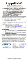
1.2 Device views
Figure 1: Front, top and side right view of device
1 Mounting flange
2 5-pin, “A”-coded M12 plug for power supply and signal contact
3 Device-specific label
4 4-pin, “D”-coded M12 socket for 10/100 Mbit/s twisted pair connections
5 Label with individual password (“Factory password”)
6 Antenna connection “Ant1” (Main)
7 Reset button
8 LED display elements
9 Antenna connection “Ant2” (Diversity)
1
2
3
4
9
6
7
8
5

Installation BAT-C2
Release
04
10/2020
19
Figure 2: Rear view of device
1.3 Power supply
For the power supply of the device, a 5-pin M12 plug (“A”-coded ) is available.
Further information:
See “Connecting the power supply and the signal contact lines” on page 24.
1.4 Ethernet port
This port is a 4-pin, “D”-coded M12 socket.
The 10/100 Mbit/s twisted pair port allows you to connect network
components according to the IEEE 802.3 10BASE-T/100BASE-TX standard.
This port supports:
Autonegotiation
Autopolarity
Autocrossing (if autonegotiation is activated)
100 Mbit/s half-duplex mode, 100 Mbit/s full duplex mode
10 Mbit/s half-duplex mode, 10 Mbit/s full duplex mode
Delivery state: Autonegotiation activated
The socket housing is electrically connected with the device housing.
1 Mounting flange
2 Mounting flange
21

20
Installation BAT-C2
Release
04
10/2020
1.4.1 Pin assignments
M12 4-pin (“D”-coded) Pin Data
1TX+
2RX+
3TX
4RX
1
23
4
/