Page is loading ...

INSTALLATION INSTRUCTIONS
66-1086-2
® U.S. Registered Trademark
Copyright © 2003 Honeywell International Inc.
All Rights Reserved
EC7823A;RM7823A
7800 SERIES Relay Modules
APPLICATION
The Honeywell EC/RM7823A Relay Module is a
microprocessor based flame detector relay that can be fitted
with any 7800 SERIES Flame Amplifier to provide relay action
from one dpdt relay when flame is or is not present. The
EC/RM7823A system consists of a relay module, wiring
subbase and flame amplifier. Options include keyboard
display module (KDM), personal computer interface, Data
ControlBus Module™, remote display mounting and
Combustion System Manager™ Software.
Functions provided by the EC/RM7823A include flame
monitoring, self-diagnostics and troubleshooting.The
EC/RM7823A is a solid state replacement for the R7023B,C
Flame Detector Relays.
The EC7823/RM7823 is a flame detector relay only. A
switchable primary control must be used to provide safe-start
check, safety lockout, load switching and other functions
required in Flame Safeguard systems.
This document provides installation and static checkout
instructions. Other applicable publications are:
SPECIFICATIONS
Electrical Ratings, see Table 3:
Voltage and Frequency:
EC7823A: 220-240 Vac +10%/-15%, 50/60 Hz ±10%.
RM7823A: 120 Vac, +10%/-15%, 50/60 Hz, ± 10%.
Power Dissipation:
10W maximum.
Maximum Total Connected Load: 2000 VA.
Fusing: Total Connected Load: 15A, type SC, Fast Blow, or
equivalent.
Environmental Ratings:
Ambient Temperature:
Operating: -40°F to 140°F (-40°C to +60°C).
Storage: -40°F to 150°F (-40°C to +66°C).
Humidity: 85% relative humidity continuous, noncondensing.
Vibration: 0.5G environment.
Approvals:
RM7823A:
Underwriters Laboratories Inc. Listed: File No. MP268,
Guide No. MCCZ.
Canadian Standards Association Certified: LR9S329-3.
Factory Mutual Approved: Report No. J.I.1V9A0.AF.
IRI Acceptable.
Federal Communications Commission:
Part 15, Class B, Emissions.
EC7823A:
Factory Mutual Approved: Report No. J.I.1V9A0.AF.
IRI Acceptable.
Federal Communications Commission:
Part 15, Class B, Emissions.
Form
Number Description
63-2278 Q7700A Network Interface Unit Product Data
65-0084 Q7800A,B 22-Terminal Wiring Subbase Product
Data
65-0090 S7800A Keyboard Display Module Product Data.
65-0091 S7810A Data ControlBus Module™ Product Data
65-0095 S7820 Remote Reset Module Product Data
65-0097 221729C Dust Cover Packing Sheet
65-0109 R7824, R7847, R7848, R7849, R7851, R7861,
R7886 Flame Amplifiers for the 7800 SERIES
Product Data
65-0131 221818A Extension Cable Assembly Product Data
65-0229 7800 SERIES Relay Modules Checkout and Test

EC7823A;RM7823A 7800 SERIES RELAY MODULES
66-1086—2 2
INSTALLATION
When Installing this Product…
1. Read these instructions carefully. Failure to follow them
could damage the product or cause a hazardous condition.
2. Check the ratings given in the instructions and marked
on the product to make sure the product is suitable for
the application.
3. Installer must be a trained, experienced, flame
safeguard service technician.
4. After installation is complete, check out the product
operation as provided in these instructions.
WARNING
Fire or Explosion Hazard.
Can cause property damage, severe injury or
death.
To prevent possible hazardous burner operation, verify
safety requirements each time a control is installed on
a burner.
WARNING
Electrical Shock Hazard/Equipment Damage
Hazard.
Can cause severe injury, death or property
damage.
Disconnect the power supply before beginning
installation. More than one power supply disconnect
may be required.
IMPORTANT
1. Wiring connections for the relay modules are unique;
refer to Fig. 2 or the correct Specifications for proper
subbase wiring.
2. Wiring must comply with all applicable codes,
ordinances and regulations.
3. Wiring must comply with NEC Class 1 (Line Voltage)
wiring.
4. Loads connected to the EC/RM7823A must not
exceed those listed on the EC/RM7823A label or the
Specifications; see Table 3 or 4.
5. All external timers must be listed or
component-recognized by authorities who have
proper jurisdiction.
6. For on-off gas-fired systems, some authorities who
have jurisdiction prohibit the wiring of any limit or
operating contacts in series between the flame
safeguard control and the main fuel valve(s).
7. Two flame detectors can be connected in parallel
with the exception of Infrared Flame Detectors
(C7015).
8. This equipment generates, uses and can radiate
radio frequency energy and, if not installed and used
in accordance with the instructions, can cause
interference with radio communications. It has been
tested and found to comply with the limits for a Class
B computing device of Part 15 of FCC rules which
are designed to provide reasonable protection
against such interference when operated in a
commercial environment. Operation of this
equipment in a residential area may cause
interference; in which case, the users at their own
expense may be required to take whatever
measures are required to correct this interference.
9. This digital apparatus does not exceed the Class B
limits for radio noise for digital apparatus set out in
the Radio Interference Regulations of the Canadian
Department of Communications.
Location
Humidity
Install the relay module where the relative humidity never
reaches the saturation point. The relay module is designed to
operate in a maximum 85% relative humidity continuous,
noncondensing, moisture environment. Condensing moisture
can cause a safety shutdown.
Vibration
Do not install the relay module where it could be subjected to
vibration in excess of 0.5G continuous maximum vibration.
Weather
The relay module is not designed to be weather tight. When
installed outdoors, the relay module must be protected by an
approved weather-tight enclosure.
Mounting Q7800 Wiring Subbase
1. Mount the Q7800 Subbase in any position except
horizontally with the bifurcated contacts pointing down.
The standard vertical position or with the bifurcated
contacts point up is recommended. Any other position
decreases the maximum ambient temperature rating.
2. Select a location on a wall, burner or electrical panel.
The wiring subbase can be mounted directly in the
control cabinet. Be sure to allow adequate clearance
for servicing, installation, access or removal of the
EC/RM7823A, dust cover, flame amplifier, flame
amplifier voltage probes, electrical signal voltage probes
and electrical field connections.
3. For surface mounting, use the back of the subbase as a
template to mark the four screw locations. Drill the pilot
holes.
4. Securely mount the subbase using four no. 6 screws
(not provided).
Wiring Subbase
WARNING
Electrical Shock Hazard.
Can cause serious injury, death or equipment/
control damage.
Disconnect the power supply before beginning
installation. More than one power supply disconnect
may be required.
1. For proper subbase wiring, refer to Figs. 2, 3, 4 or 5.
2. For proper remote wiring of the Keyboard Display
Module, refer to the Specifications for the Keyboard
Display Module (65-0090), Network Interface Unit
(63-2278), Data ControlBus Module™ (65-0091) or
Extension Cable Assembly (65-0131).
3. Disconnect the power supply from the main disconnect
before beginning installation to prevent electrical shock
and equipment damage. More than one disconnect may
be required.
4. All wiring must comply with all applicable electrical
codes, ordinances and regulations. Wiring must comply
with NEC, Class 1 (Line Voltage) wiring.
5. For recommended wire size and type, see Table 1.
6. For recommended grounding practices, see Table 2.

EC7823A;RM7823A 7800 SERIES RELAY MODULES
3 66-1086—2
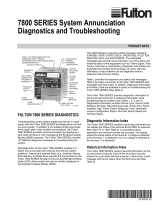
Fig. 1. Internal block diagram of the EC/RM7823A (See Fig. 6 for detailed wiring instructions).
Table 1. Recommended wire sizes and part numbers.
Table 2. Recommended grounding practices.
Application Recommended Wire Size Recommended Part Numbers
Line voltage terminals 14, 16 or 18 AWG copper conductor, 600 volt insulation,
moisture-resistant wire.
TTW60C, THW75C, THHN90C.
Keyboard Display Module 22 AWG two-wire twisted pair with ground, or five wire. Belden® 8723 shielded cable or equivalent.
Data ControlBus Module™ 22 AWG two-wire twisted pair with ground, or five wire. Belden® 8723 shielded cable or equivalent.
Remote Reset Module 22 AWG two-wire twisted pair, insulated for low voltage. —
Communications Interface
ControlBus Module
22 AWG two-wire twisted pair with ground. Belden® 8723 shielded cable or equivalent.
13 Vdc full-wave rectified
transformer power input.
18 AWG wire insulated for voltages and temperatures
for given application.
TTW60C, THW75C, THHN90C.
Ground Type Recommended Practice
Earth ground
(subbase and
relay module).
1. Use to provide a connection between the subbase and the control panel of the equipment. Earth ground
must be capable of conducting enough current to blow the 15A fast acting fuse (or breaker) in the event of an
internal short circuit.
2. Use wide straps or brackets to provide minimum length, maximum surface area ground conductors. If a
leadwire must be used, use 14 AWG copper wire.
3. Make sure that mechanically tightened joints along the ground path are free of nonconductive coatings and
protected against corrosion on mating surfaces.
MICROCOMPUTER
RESET
PUSHBUTTON
STATUS
LEDs
POWER SUPPLY
PLUG-IN
FLAME
AMPLIFIER
RELAY
DRIVE
CIRCUIT
CONTROL
POWER
TEST
JACK
FIELD WIRING
INTERNAL WIRING
NC
COMMON
NO
NC
A1
120 Vac/220-240 Vac,
50/60 Hz FLAME SIGNAL
TEST
PROVIDE DISCONNECT MEANS AND
OVERLOAD PROTECTION AS REQUIRED.
OUTPUTS SHOWN ARE WHEN THE
DEVICE DOES NOT SENSE FLAME.
L1
(HOT)
L2
3
A2
B1
10
8
9
14
F
G
22
1
COMMON13
NO15
L2
OPTIONAL KEYBOARD
DISPLAY MODULE
REMOTE
RESET
DDL
DDL
COMMUNICATIONS
RS485
1
2
3
5
1
M15079
A
9K
B2
9K
2
2

EC7823A;RM7823A 7800 SERIES RELAY MODULES
66-1086—2 4
Fig. 2. Wiring subbase for EC/RM7823A.
7. Recommended wire routing of leadwires:
a. Do not run high voltage ignition transformer wires
in the same conduit with the flame detector.
b. Do not route flame detector leadwires in conduit
with line voltage circuits.
c. Enclose flame detector leadwires without armor
cable in metal cable or conduit.
d. Follow directions in flame detector instructions.
8. Maximum wire lengths:
a. EC/RM7823A leadwires: The maximum leadwire
length is 300 feet to terminal inputs.
b. Flame Detector leadwires: The maximum flame
sensor leadwire length is limited by the flame
signal strength.
9. Make sure loads do not exceed the terminal ratings.
Refer to the label on the EC/RM7823A or to the ratings
in Tables 3 and 4.
Final Wiring Check
1. Check the power supply circuit. The voltage and
frequency tolerance must match those of the
EC/RM7823A. A separate power supply circuit may
be required for the EC/RM7823A. Add the required
disconnect means and overload protection.
2. Check all wiring circuits and complete the Static
Checkout in Table 5 before installing the EC/RM7823A
on the subbase.
3. Install all electrical connectors.
4. Restore panel power.
M15080GR
G
L2
3
4
5
6
7
8
9
10
F
(L1)
13
14
15
16
17
18
19
20
21
22
12
MASTER
SWITCH
NORMALLY
CLOSED
NORMALLY
OPEN
COMMON
FLAME DETECTOR
120V, 50/60 Hz (RM7823); 220-240V, 50/60 Hz (EC7823) POWER SUPPLY. PROVIDE
DISCONNECT MEANS AND OVERLOAD PROTECTION AS REQUIRED.
DO NOT CONNECT ANY WIRES TO UNUSED TERMINALS
OUTPUTS SHOWN ARE WHEN THE DEVICE DOES NOT SEE FLAME.
SEE FLAME DETECTOR INSTALLATION INSTRUCTIONS FOR CORRECT WIRING.
NOTE: FOR EC7823, A 220/240V TO 120V, 10VA, STEP-DOWN TRANSFORMER IS REQUIRED.
L1
(HOT)
L2
1
1
Q7800
2
2
NORMALLY
CLOSED
NORMALLY
OPEN
COMMON
4
4
3
3
3

EC7823A;RM7823A 7800 SERIES RELAY MODULES
5 66-1086—2
Table 3. Terminal Ratings for RM7823A.
a See Table 2.
Table 4. Terminal Ratings for EC7823A.
a Total load current, excluding burner/boiler motor, cannot exceed 5A, 25A inrush.
b A 220-240 Vac to 120 Vac, 10 VA minimum stepdown transformer (not provided) must be used to drive the shutter.
Terminal Number Description Ratings
GFlame Sensor Grounda—
Earth G Earth Grounda—
L2(N) Line Voltage Common —
3 Line Voltage Supply (L1) 120 Vac (+10%/-15%), 50/60 Hz (±10%).
4-7 Unused —
8 9KA Common —
9 9KA1 N.O. 9.8 FLA, 58.8 ALR at 120 Vac.
10 9KA2 N.C. 1A Pilot Duty at 120 Vac.
F(11) Flame Sensor 60 to 220 Vac, current limited.
12 Unused. —
13 9KB Common —
14 9KB1 N.C. 1A Pilot Duty at 120 Vac; also rated for 5V control circuits.
15 9KB2 N.O. 1A Pilot Duty at 120 Vac; also rated for 5V control circuits.
16-21 Unused —
22 Shutter 120 Vac, 0.5A.
Terminal Number Description Ratingsa
GFlame Sensor Grounda—
Earth G Earth Grounda—
L2(N) Line Voltage Common —
3 Line Voltage Supply 220-240 Vac (+10%/-15%), 50/60 Hz (±10%).
4-7 Unused —
8 9KA Common —
9 9KA1 N.O. 220-240 Vac, 4A at PF = 0.5, 20A inrush.
10 9KA2 N.C. 220-240 Vac, 2A at PF = 0.2.
F(11) Flame Sensor 16 to 220 Vac, current limited.
12 Unused —
13 9KB Common —
14 9KB1 N.C. 220-240 Vac, 0.5A at PF = 0.5.
15 9KB2 N.O. 220-240 Vac, 0.5A at PF = 0.5.
16-21 Unused —
22 Shutter 220-240 Vac, 0.25Ab

EC7823A;RM7823A 7800 SERIES RELAY MODULES
66-1086—2 6
Mounting EC/RM7823A Relay Module
1. Mount the EC/RM7823A on the Q7800 Subbase
vertically, or mount horizontally with the knife blade
terminals pointing down. When mounted on the Q7800A
Wiring Subbase, the EC/RM7823A must be in an
electrical enclosure.
2. When mounting in an electrical enclosure, provide
adequate clearance for servicing, installation and
removal of the EC/RM7823A, keyboard display module,
flame amplifier, flame amplifier signal voltage probes,
electrical signal voltage probes, and electrical
connections.
a. Allow an additional two inches below the
EC/RM7823A for the flame amplifier mounting.
b. Allow an optional three inches minimum to both
sides of the EC/RM7823A for electrical signal
voltage probes.
3. Make sure no subbase wiring is projecting beyond the
terminal blocks. Tuck in wiring against the back of the
subbase so it does not interfere with the knife blade
terminals or bifurcated contacts.
IMPORTANT
The EC/RM7823A must be installed with a plug-in
motion rather than a hinge action.
4. Mount the EC/RM7823A by aligning the four L shaped
corner guides and knife blade terminals with the
bifurcated contacts on the wiring subbase and securely
tightening the two screws without deforming the plastic.
Mounting Other System Components (Fig. 3)
Some other system components are shown in Fig. 3. Mount
other required and optional system components by referring to
the instructions provided with each component.
Fig. 3. EC/RM7823A Relay Module, exploded view.
HONEYWELL
POWER
FLAME
RESET
DUST
COVER
WIRING
SUBBASE
CAPTIVE
MOUNTING
SCREW
RELAY
MODULE
SEQUENCE
STATUS
LED PANEL
RESET
BUTTON
FLAME
AMPLIFIER
BURNER CONTROL
M17823
ALARM

EC7823A;RM7823A 7800 SERIES RELAY MODULES
7 66-1086—2
OPERATION
Sequence of Operation
The EC/RM7823A has the following operating sequences,
see Fig.4 and Table 5. The EC/RM7823A LED provide
positive visual indication of the program sequence: POWER,
FLAME and ALARM.
Fig. 4. Sequence status LEDs.
Table 5. LED sequence status display information.
Standby
The EC/RM7823A is ready to respond to sensing of a flame or
flame simulating condition. The green POWER LED blinks
every four seconds, indicating that the relay module is doing
internal hardware checks.
Run
The EC/RM7823A pulls in the internal dpdt relay and turns on
the FLAME LED when a flame or flame simulating condition
exists. The relay module is now in the Run sequence.
Static Checkout
After checking all wiring, perform this checkout before
installing the EC/RM7823A on the subbase. These tests verify
the Q7800 Wiring Subbase is wired correctly, and the external
controllers, limits, interlocks, actuators, valves, transformers,
motors and other devices are operating properly.
WARNING
Explosion and/or Electrical Shock Hazard.
Can cause serious injury, death or equipment
damage.
1. Close all manual fuel shutoff valve(s) before starting
these tests.
2. Use extreme care while testing the system. Line
voltage is present on most terminal connections
when power is on.
3. Open the master switch before installing or
removing a jumper on the subbase.
4. Before continuing to the next test, be sure to
remove test jumper(s) used in the previous test.
5. Replace all limits and interlocks that are not
operating properly. Do not bypass limits and
interlocks.
CAUTION
Equipment Damage Hazard.
Improper testing will cause serious internal
damage.
Do not perform a dielectric test with the EC/RM7823A
installed. Internal surge protectors can break down
and conduct a current. This can cause the
EC/RM7823A to fail the dielectric test or possibly
destroy the internal lightning and high current
protection.
Equipment Recommended
1. Voltmeter (1M ohm/volt minimum sensitivity) set on the
0 to 300 Vac scale.
2. Two jumper wires, no. 14 wire, insulated, 12 in.
(305 mm) long with insulated alligator clips at both ends.
Burner Sequence LED Energized
Standby POWER, FLAME and ALARM.
Run POWER, FLAME and ALARM.
Reset/Alarm Test POWER, FLAME and ALARM.
CAPTIVE
MOUNTING
SCREW
DUST
COVER
RELAY
MODULE
FLAME
AMPLIFIER
RESET PUSHBUTTON
SEQUENCE
STATUS
LEDS
M7889

66-1086—2 G.R. Rev. 12-03 www.honeywell.com
EC7823A;RM7823A 7800 SERIES RELAY MODULES
Automation and Control Solutions
Honeywell International Inc. Honeywell Limited-Honeywell Limitée
1985 Douglas Drive North 35 Dynamic Drive
Golden Valley, MN 55422 Scarborough, Ontario
M1V 4Z9
General Instructions
1. Perform all applicable tests listed in Static Checkout,
Table 6, in the order listed.
2. Make sure all manual fuel shutoff valve(s) are closed.
3. Perform only those tests designated for the specific
EC/RM7823A model being tested.
4. Raise the setpoint of the operating controller to simulate
a call for heat.
5. For each test, open the master switch and install the
jumper wire(s) between the subbase wiring terminals
listed in the Test Jumpers column.
6. Close the master switch before observing operation.
7. Read the voltage between the subbase wiring terminals
listed in the Voltmeter column.
8. If there is no voltage or the operation is abnormal,
check the circuits and external devices as described
in the last column.
9. Check all wiring for correct connections, tight terminal
screws, correct wire, and proper wiring techniques.
Replace all damaged or incorrectly sized wires and
tighten any loose terminal screws.
10. Replace faulty controllers, limits, interlocks, actuators,
valves, transformers, motors and other devices as
required.
11. Make sure normal operation is obtained for each
required test before continuing the checkout.
12. After completing each test, be sure to remove the
test jumper(s).
WARNING
Explosion hazard.
Can cause serious injury or death.
Be sure all manual fuel shutoff valves are closed.
Table 6. Static checkout.
Test
Number
Test
Jumpers Voltmeter Normal Operation
If Operation is Abnormal,
Check the Items Listed Below
1 — L2-3 Line voltage at terminal 3. 1. Master Switch.
2. Power connected to the master switch.
3. Overload protection (fuse, circuit
breaker, etc.) has not opened the power
line.
2 8-9 — Load operation without flame sighting. Load connections to terminals 8 and 9.
3 8-10 — Load operation when flame detected. Load connections to terminals 8 and 10.
4 13-14 — Load operation without flame sighting. Load connections to terminals 13 and 14.
5 13-15 — Load operation when flame detected. Load connections to terminals 13 and 15.
FINAL ALL
CAUTION
Equipment Damage Hazard.
Leaving jumpers in place will damage the equipment.
After completing these tests, open the master switch and remove all test jumpers from the
subbase terminals. Remove any bypass jumpers from limits.
/