Page is loading ...

1
97% Modulating Gas Furnaces
34.5" Chassis ACVM, AMVM, GCVM, GMVM
& Accessories
RS6612009
August 2014
This manual is to be used by qualified, professionally trained HVAC technicians only. Goodman does
not assume any responsibility for property damage or personal injury due to improper service
procedures or services performed by an unqualified person.
Copyright © 2014 Goodman Company, L.P.
Service Instructions
is a registered trademark of Maytag Corporation or its related companies and is used under license to Goodman Company, L.P., Houston, TX. All rights reserved.

2
IMPORTANT INFORMATION
Pride and workmanship go into every product to provide our customers with quality products. It is possible,
however, that during its lifetime a product may require service. Products should be serviced only by a qualified
service technician who is familiar with the safety procedures required in the repair and who is equipped with the
proper tools, parts, testing instruments and the appropriate service manual. REVIEW ALL SERVICE INFORMATION
IN THE APPROPRIATE SERVICE MANUAL BEFORE BEGINNING REPAIRS.
IMPORTANT NOTICES FOR CONSUMERS AND SERVICERS
RECOGNIZE SAFETY SYMBOLS, WORDS AND LABELS
WARNING
T
O PREVENT THE RISK OF PROPERTY DAMAGE, PERSONAL INJURY, OR DEATH,
DO NOT STORE COMBUSTIBLE MATERIALS OR USE GASOLINE OR OTHER
FLAMMABLE LIQUIDS OR VAPORS IN THE VICINITY OF THIS APPLIANCE.
TABLE OF CONTENTS
WARNING
HIGH VOLTAGE
D
ISCONNECT ALL POWER BEFORE SERVICING OR
INSTALLING THIS UNIT.
MULTIPLE POWER SOURCES MAY
BE PRESENT.
FAILURE TO DO SO MAY CAUSE PROPERTY
DAMAGE, PERSONAL INJURY OR DEATH.
WARNING
G
OODMAN WILL NOT BE RESPONSIBLE FOR ANY INJURY OR PROPERTY DAMAGE ARISING FROM IMPROPER SERVICE OR SERVICE PROCEDURES.
I
F YOU INSTALL OR PERFORM SERVICE ON THIS UNIT, YOU ASSUME RESPONSIBILITY FOR ANY PERSONAL INJURY OR PROPERTY DAMAGE WHICH
MAY RESULT.
M
ANY JURISDICTIONS REQUIRE A LICENSE TO INSTALL OR SERVICE HEATING AND AIR CONDITIONING EQUIPMENT.
IMPORTANT INFORMATION ......................2-3
PRODUCT IDENTIFICATION .................... 4 - 7
ACCESSORIES ................................... 8 - 10
LIGHTING INSTRUCTIONS ......................... 11
PRODUCT DESIGN ............................ 12 - 23
OPERATION .................................... 24 - 46
SERVICE AND OPERATION......................... 47
OPERATIONAL CHECKS ...................... 48 - 49
MAINTENANCE ...................................... 50
SERVICING TABLE OF CONTENTS ................ 51
SERVICING ..................................... 52 - 58
TROUBLESHOOTING.......................... 59 - 63
STATUS CODES ...................................... 64
WIRING DIAGRAM................................... 65

3
IMPORTANT INFORMATION
Special Warning for Installation of Furnace or Air Handling Units in
Enclosed Areas such as Garages, Utility Rooms or Parking Areas
Carbon monoxide producing devices (such as an automobile, space
heater, gas water heater, etc.) should not be operated in enclosed areas
such as unventilated garages, utility rooms or parking areas because of
the danger of carbon monoxide (CO) poisoning resulting from the exhaust
emissions. If a furnace or air handler is installed in an enclosed area such
as a garage, utility room or parking area and a carbon monoxide producing
device is operated therein, there must be adequate, direct outside
ventilation.
This ventilation is necessary to avoid the danger of CO poisoning which
can occur if a carbon monoxide producing device continues to operate in
the enclosed area. Carbon monoxide emissions can be (re)circulated
throughout the structure if the furnace or air handler is operating in any
mode.
CO can cause serious illness including permanent brain damage or death.
To locate an authorized servicer, please consult your telephone book or the dealer from whom you purchased this
product. For further assistance, please contact:
CONSUMER INFORMATION LINE
GOODMAN
®
BRAND PRODUCTS
TOLL FREE
1-877-254-4729 (U.S. only)
email us at:
fax us at: (731) 856-1821
(Not a technical assistance line for dealers.)
CONSUMER INFORMATION LINE
AMANA
®
BRAND PRODUCTS
TOLL FREE
1-877-254-4729 (U.S. only)
email us at: hac.consumer[email protected]
fax us at: (731) 856-1821
(Not a technical assistance line for dealers.)
Outside the U.S., call 1-713-861-2500.
(Not a technical assistance line for dealers.) Your telephone company will bill you for the call.

PRODUCT IDENTIFICATION
4
G M V M 97 060 3 B N A A
SUPPLY TYPE
M: Upflow/Horizontal
C: Downflow/Horizontal
FURNACE TYPE
V: Variable-Speed
AFUE
97: 97%
NOMINAL INPUT
060: 60,000 Btuh
080: 80,000 Btuh
100: 100,000 Btuh
120: 120,000 Btuh
AIRFLOW
CAPABILITY
@ 0.5" ESP
3: 1200
4: 1600
5: 2000
CABINET
WIDTH
B: 17-1/2"
C: 21"
D: 24-1/2"
ADDITIONAL
FEATURES
N: Natural Gas
X: Low NOx
PRODUCT
TYPE:
G: Goodman
®
Brand
A: Amana
®
Brand
MAJOR
REVISION
A: Initial Release
MINOR
REVISION
A: Initial Release
COMMUNICATION FEATURE
M: Modulating Furnace
4-Wire Communication Ready

PRODUCT IDENTIFICATION
5
MODEL: AMVM97 REV AA
Equipment Type Amana Brand Residential Gas Furnace
Heating Stages Modulating (35% - 100% of rated input)
Cooling Stages Two
Control Type ClimateTalk
™ or Conventional 24 Volt
Blower Motor Type 4 Wire Variable Speed ECM
AMVM97
0603BN 0803BN 0804CN 1005CN 1205DN
Installation Positions
UF, Hor L/R UF, Hor L/R UF, Hor L/R UF, Hor L/R UF, Hor L/R
BTUH Input Range (X 1000)
21 - 60 28 - 80 28 -80 35 - 100 42 - 120
A/C Capable Tons
1.5 - 3 1.5 - 3 2 - 4 2 - 5 2 - 5
Cabinet Hight "
34.5 34.5 34.5 34.5 34.5
Cabinet Width "
17.5 17.5 21 21 24.5
Heating CFM @ 100% Firing Rate
1059 1316 1337 1870 1940
ECM Motor H.P.
Draft Inducer
Gas Valve
24 VAC Heating Inputs
24 VAC Cooling Inputs
Primary Heat Exchanger
Accessory Terminals
Gas Line Entry
Revision Attributes First revision of 34.5" modulating up flow furnace
Left or Right
3
Ø Variable Speed
24 VAC, Modulates by Pneumatic signal
W1 / W2
Y1 / Y2
Stainless Steel
EAC terminal, HUM IN / HUM OUT terminals
MODEL: GMVM97 REV AA
Equipment Type Goodman Brand Residential Gas Furnace
Heating Stages Modulating (35% - 100% of rated input)
Cooling Stages Two
Control Type ClimateTalk
™ or Conventional 24 Volt
Blower Motor Type 4 Wire Variable Speed ECM
GM V M9 7
0603BN 0803BN 0804CN 1005CN 1205DN
Installation Positions
UF, Hor L/R UF, Hor L/R UF, Hor L/R UF, Hor L/R UF, Hor L/R
BTUH Input Range (X 1000)
21 - 60 28 - 80 28 -80 35 - 100 42 - 120
A/C Capable Tons
1.5 - 3 1.5 - 3 2 - 4 2 - 5 2 - 5
Cabinet Hight "
34.5 34.5 34.5 34.5 34.5
Cabinet Width "
17.5 17.5 21 21 24.5
Heating CFM @ 100% Firing Rate
1059 1316 1337 1870 1940
ECM Motor H.P.
Draft Inducer
Gas Valve
24 VAC Heating Inputs
24 VAC Cooling Inputs
Primary Heat Exchanger
Accessory Terminals
Gas Line Entry
Revision Attributes First revision of 34.5" modulating up flow furnace
3
Ø Variable Speed
Left or Right
EAC terminal, HUM IN / HUM OUT terminals
24 VAC, Modulates by Pneumatic signal
W1 / W2
Y1 / Y2
Aluminized Steel
MODEL: GCVM97
REV AA
Equipment Type Goodman Brand Residential Gas Furnace
Heating Stages Modulating (35% - 100% of rated input)
Cooling Stages Two
Control Type ClimateTalk
™ or Conventional 24 Volt
Blower Motor Type 4 Wire Variable Speed ECM
GCV M97
0603BN 0803BN 0804CN 1005CN
Installation Positions
CF, Hor L/R CF, Hor L/R CF, Hor L/R CF, Hor L/R
BTUH Input Range (X 1000)
21 - 60 28 - 80 28 -80 35 - 100
A/C Capable Tons
1.5 - 3 1.5 - 3 2 - 4 2 - 5
Cabinet Hight "
34.5 34.5 34.5 34.5
Cabinet Width "
17.5 17.5 21 21
Heating CFM @ 100% Firing Rate
950 1146 1325 1779
ECM Motor H.P.
Draft Inducer
Gas Valve
24 VAC Heating Inputs
24 VAC Cooling Inputs
Primary Heat Exchanger
Accessory Terminals
Gas Line Entry
Revision Attributes First revision of 34.5" modulating counter flow furnace
Left or Right
3
Ø Variable Speed
24 VAC, Modulates by Pneumatic signal
W1 / W2
Y1 / Y2
Aluminized Steel
EAC terminal, HUM IN / HUM OUT terminals
MODEL: ACVM97
REV AA
Equipment Type Amana Brand Residential Gas Furnace
Heating Stages Modulating (35% - 100% of rated input)
Cooling Stages Two
Control Type ClimateTalk
™ or Conventional 24 Volt
Blower Motor Type 4 Wire Variable Speed ECM
ACVM97
0603BN 0803BN 0804CN 1005CN
Installation Positions
CF, Hor L/R CF, Hor L/R CF, Hor L/R CF, Hor L/R
BTUH Input Range (X 1000)
21 - 60 28 - 80 28 -80 35 - 100
A/C Capable Tons
1.5 - 3 1.5 - 3 2 - 4 2 - 5
Cabinet Hight "
34.5 34.5 34.5 34.5
Cabinet Width "
17.5 17.5 21 21
Heating CFM @ 100% Firing Rate
950 1146 1325 1779
ECM Motor H.P.
Draft Inducer
Gas Valve
24 VAC Heating Inputs
24 VAC Cooling Inputs
Primary Heat Exchanger
Accessory Terminals
Gas Line Entry
Revision Attributes First revision of 34.5" modulating counter flow furnace
Left or Right
3
Ø Variable Speed
24 VAC, Modulates by Pneumatic signal
W1 / W2
Y1 / Y2
Stainless Steel
EAC terminal, HUM IN / HUM OUT terminals

PRODUCT IDENTIFICATION
6
MODEL # MFG # DESCRIPTION
AFE18-60A
N/A
Fossil Fuel Kit.
The AFE18-60A control is designed for use where the indoor coil is located above/downstream
of a gas or fossil fuel furnace when used with a heat pump. It will operate with single and two stage heat
pumps and single and two stage furnaces. The AFE18-60A control will turn the heat pump unit off when the
furnace is turned on. An anti-short cycle feature initiates a 3 minute timed off delay when the compressor goes
off.
AMU1620
AMU1625
AMU2020
AMU2025
GMU1620
GMU1625
GMU2020
GMU2025
P1251305F
P1251306F
P1251307F
P1251308F
N/A
Media Air Cleaner
. For use with current architectural grey Goodman® and Amana® Brand 96% variable speed,
modulating furnace models. The Amana (AMU*) and Goodman (GMU*) Media Air Cleaner is a high efficiency
air filtration device designed to remove dirt, dust, pollen and other microscopic particles from the air passing
through it. Flexible performance range up to 2,000 CFM capacity. The air cleaner should be installed in the
system so that all the system air is circulated through the air cleaner. The air cleaner will only remove the
airborne contaminants delivered to it. Maximum performance is obtained when the system blower is set for
continuous operation. Carbon filters (optional) are available.
ASAS-10
ASAS-11
ASAS-12
ASAS-18
P1251301F
P1251302F
P1251303F
P1251304F
Electronic Air Cleaner
. For use with current architectural grey Goodman® and Amana® Brand 96% variable
speed, modulating furnace models. The High-Efficiency Electronic Air Cleaner is designed to remove air
contaminants down to .01 microns. Carbon filters (optional) remove odors. Dual indicator lights show unit
operation at a glance. Electronic proving switch cycles the air cleaner On/Off with the system fan. Durable
powder-coat paint finish resists corrosion.
CFSB17
CFSB21
CFSB24
N/A
Counterflow Subbase Kit
. For use with Goodman®, & Amana® Brand modulating 34.5" furnace models.
These kits are available for the following furnace widths: 17.5" wide (CFSB17), 21" wide (CFSB21) and 24"
wide (CFSB24). The kits must be used to prevent excessive temperature from reaching combustible materials,
if the furnace is installed on a combustible floor. This subbase effectively separated the furnace base and
plenum from combustible materials. To ensure safe installation, do not install the counterflow floor base
directly on carpeting, tile, or other combustible material other than wood flooring.
CTK01
CTK01A A
Communicating Thermostat Kit
- Digitally communicating touchscreen thermostat, a necessary part of any
communicating system. Designed for use with compatible Amana® Brand or Goodman® Brand Air Handlers
or Furnaces and outdoor split AC or Heat Pump units. This thermostat supports up to three stages of heat, two
stages of cooling, dual fuel applications, dehumidification, filter maintenance reminders, outdoor temperature
display and advanced menus including diagnostics. The CTK01AA kit includes a communicating touchscreen
thermostat and sub base, 230V-24V 40va transformer, terminal blocks(2), wire jumpers,
mounting screws, installation manual and homeowner guide.
CTK01BA
CTK01BA
Communicating Thermostat Kit
- Digitally communicating touchscreen thermostat, a necessary part of any
communicating system. Designed for use with compatible Amana® Brand or Goodman® Brand Air Handlers
or Furnaces and outdoor split AC or Heat Pump units. This thermostat supports up to three stages of heat, two
stages of cooling, dual fuel applications, dehumidification, filter maintenance reminders, outdoor temperature
display and advanced menus including diagnostics. The CTK01BA kit includes a communicating touchscreen
thermostat and sub base, terminal blocks(2), mounting screws, installation manual and homeowner guide.
CTK02**
CTK02**
Communicating Thermostat Kit
- Digitally communicating thermostat, a necessary part of any communicating
system. Designed for use with compatible Amana® Brand or Goodman® Brand Air Handlers or Furnaces and
outdoor split AC or Heat Pump units. The CTK02** thermostat features full color, high definition display,
advanced programming options including humidification control & heat and cool maximum temperature
settings, a USB plug allowing dealers the ability to insert pre-programmed operating parameters and dealer
information by use of an online data entry system.
CTK03A*
CTK03A *
Communicating Thermostat Kit
- Digitally communicating touchscreen thermostat from Honeywell. Designed
for use with compatible Amana® Brand or Goodman® Brand Air Handlers or Furnaces and outdoor split AC or
Heat Pump units. The CTK03A* thermostat features full color high definition display, can be used with
RedLINK wireless accessories.
CTK04A*
CTK04A *
Communicating Thermostat Kit
- Digitally communicating touchscreen thermostat from Honeywell. Designed
for use with compatible Amana® Brand or Goodman® Brand Air Handlers or Furnaces and outdoor split AC or
Heat Pump units. The CTK04A* thermostat features full color high definition display, can be used with
RedLINK wireless accessories. Split system inverter capable.

PRODUCT IDENTIFICATION
7
MODEL # MFG # DESCRIPTION
DCVK-20
(CVENT-2)
DCVK-30
(CVENT-3)
N/A
Concentric Vent Kit
. For use with Amana® Brand Modulating furnace models. This kit is designed to allow
terminations of a direct vent furnace to be "concentrically" vented through a wall or roof. This kit allows a single
penetration to support terminations for both the vent/flue and the combustion air intake pipe. The DCVK-20 (2")
and DCVK-30 (3") kits are certified for models listed above. See specification sheets on future models for use
of the vent kit.
DEHUM1
P1227801F
Dehumidistat.
For use with Goodman® & Amana® Brand two-stage variable speed modulating furnace
models. Wall mounted, 24 volt humidity control available as a Dehumidistat used to reduce the airflow in the air
conditioning mode when necessary to lower the humidity in an occupied home to prevent dew build-up
associated with high humidity levels. This control features a moisture-sensitive nylon element and also
provides positive ON-OFF settings for manual operation. The control is a normally closed switch that opens on
humidity rise causing the blower to switch to a lower speed to control the humidity within the structure.
EFR02
N/A
External Filter Rack Kit
. For use with Goodman
®
and Amana
®
Brand 97% upflow, variable speed *MVM 34.5"
modulating gas furnaces. This kit is intended to provide a location, external to the furnace casing for installation
of a permanent filter. The rack is mounted over the indoor air blower compartment area of either side panel,
and provide filter retention as well as a location for attaching return air ductwork.
0170K00000S
N/A
Side Wall Only Concentric Vent Kit
. For use with 96% modulating furnace models. This kit is to be used with
2" - 3" vent systems. The vent kit must terminate outside the structure. This kit is NOT intended for use with
single pipe (indirect vent) installations.
0170K00001S
N/A
Side Wall Only Concentric Vent Kit
. For use with 96% modulating furnace models. This kit is to be used with
2" vent systems. The vent kit must terminate outside the structure. This kit is NOT intended for use with single
pipe (indirect vent) installation
LPLP03
N/A
LP Gas Low Pressure Kit
. Designed for application on Goodman® and Amana® Brand's 80% and 90% single-
stage, two-stage and modulating furnaces converted to LP gas. The kit monitors gas line pressure with a
pressure switch and will open the circuit to the gas valve if the LP tank pressure gets low.
LPM-09
N/A
LP Conversion Kit
Converts a 34.5" modulating furnace to operate on L.P. gas. The kit contains an L.P. gas
valve and a set of six L.P. orifices.
RF000142
N/A
Drain Coupling Kit
For use when the drain/vent elbow has been removed in a horizontal left installation. This
kit prevents condensate from getting in the inducer and routes the condensate to a drain.

ACCESSORIES
8
Model
Number
AFE180-60A
AMU / GMU
ASAS / GSAS
CFSB17
CFSB21
RF000142
CTK01*
CTK02*
CTK03*
CTK04*
Description
Fossil Fuel Kit
Media Air Cleaners
Electronic
Air Cleaner
Counterflow Subbase
17.5"
Counterflow Subbase
21"
Drain Coupling
Kit
Communicating
Thermostat Kit
Com Thermostat Kit-
Modulating, High Def.
Com Thermostat Kit-
Modulating, High Def
Com Thermostat Kit-
Modulating, High Def
*MVM970603BN** X X X X X X X X
*MVM970803BN** X X X X X X X X
*MVM970804CN** X X X X X X X X
*MVM971005CN** X X X X X X X X
*MVM971205DN** X X X X X X X X
*CVM970603BN** X X X X X X X X X
*CVM970803BN** X X X X X X X X X
*CVM970804CN** X X X X X X X X X
*CVM971005CN** X X X X X X X X X
Model
Number
0170K00000S
0170K00001S
DCVK-20
DCVK-30
DEHUM1
EFR02
LPLP03
LPM-09
Description
Concentric Side Wall
Vent Kit (3")
Concentric Side Wall
Vent Kit (2")
Concentric Vent Kit (2")
Concentric Vent Kit (3")
Dehumidistat
External Filter Kit
Low LP Tank Protection
L.P. Kit
*MVM970603BN** X X X X X X X X
*MVM970803BN** X X X X X X X X
*MVM970804CN** X X X X X X X X
*MVM971005CN** X X X X X X X X
*MVM971205DN** X X X X X X X X
*CVM970603BN** X X X X X X X X
*CVM970803BN** X X X X X X X X
*CVM970804CN** X X X X X X X X
*CVM971005CN** X X X X X X X X
97% Mod Furnace Accessories

ACCESSORIES
9
Vent
Maintain 12" (18" for Canada)
minimum clearance above highest
anticipated snow level. Maximum of
24" above roof.
Combustion Air
Roof Boot/Flashing
(Field Supplied)
Support (Field Supplied)
45 Elbow
(Field Supplied)
Combustion Air
Vent
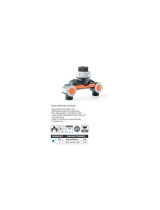
CONCENTRIC VENT CONVERSION KIT (DCVK-20 & DCVK-30 [CVENT-2 & CVENT-3*])
DCVK
(Vertical Installation)
DCVK
(Horizontal Installation)
The DCVK-20 (2") or the DCVK-30 (3") is a concentric vent
kit approved with furnaces listed in this manual.
This concentric vent kit allows for vertical or horizontal
vent termination. The illustrations give a brief view of
the kit and its application.
Vent
Combustion Air
Flush to
1" maximum
45 Elbow
(Field Supplied)
Combustion Air
Vent
Strap
(Field Supplied)
EXTERNAL FILTER RACK (EFR02)
Used on 97% Upflow Modulating Furnaces
BLOWER DECK
SCREWS
SLOTS IN FILTER
CLEAR SCREWS
ON UNIT
FRONT
OF UNIT
RETURN AIR
CUTOUT AREA
LOWER EDGE
SCREW
FILTER RACK ASSEMBLY
(FACE FILTER OPENING
TOWARDS FRONT
OF UNIT)
UNIT SIDE
PANEL
BASE
OF UNIT
See the section in this manual under "Vent Flue and Com-
bustion Air Pipe Terminations" for more information or
consult the Installation and Operating Instructions (IO-
619*).
DCVK-20 & DCVK-30 are also known as CVENT-2 & CVENT-3

ACCESSORIES
10
SIDE WALL VENT KIT (0170K00000S)
This side wall only vent kit #0170K00000S is to be used
with 2” - 3” vent systems. This kit is NOT intended for
use with single pipe (non-direct vent) installations.
The vent kit must terminate outside the structure and may
be installed with the intake and exhaust pipes located side-
by-side or with one pipe above the other.
See the section in this manual under "Vent Flue and Com-
bustion Air Pipe Terminations" for more information or
consult the Installation Instructions (IO-635).
SIDE WALL VENT KIT (0170K00001S)
This side wall only vent kit #0170K00001S is to be used
with 2” vent systems. This kit is NOT intended for use
with single pipe (non-direct vent) installations.
The vent kit must terminate outside the structure and may
be installed with the intake and exhaust pipes located side-
by-side or with one pipe above the other.
See the section in this manual under "Vent Flue and Com-
bustion Air Pipe Terminations" for more information or
consult the Installation Instructions (IO-805).
LPLP03 LOW LP GAS PRESSURE SHUT-OFF KIT
Installation of the LPLP03 kit is recommended on every LP
converted furnace to protect the furnace against low LP
gas supply pressure. Low LP supply pressure can cause poor
combustion and carbon in the heat exchanger. The LPLP03
kit will open the electrical circuit to the gas valve in the
event of low supply pressure. The kit contains a pressure
switch, gas fittings and electrical harness to connect the
switch in series with the gas valve.
LPM-09 LP CONVERSION KIT
This furnace is factory equipped to operate on Natural Gas
but may be field converted to operate on LP gas. To con-
vert a *MVM97 or *CVM97 furnace to operate on LP gas,
the LPM-09 conversion kit must be used. The LPM-09 kit
contains a modulating gas valve ready for use with LP gas,
as well as a set of 1.25 mm orifices to replace the factory
installed natural gas orifices. Do not attempt to convert or
adjust a modulating furnace gas valve. Factory burners
are suitable for both gases, L.P. and Natural. Burner re-
placement is not required when the furnace is converted
for use with L.P. gas.
AFE18-60A DUAL FUEL ACCESSORY
When installing the modulating furnace with a heat pump,
the preferred installation would include a communicating
thermostat. A communicating thermostat provides control
of gas heat and heat pump operation and eliminates the
need for a separate dual fuel control. A legacy dual fuel
thermostat could also be used with 24 volt wiring to con-
trol the gas furnace and heat pump. If a communicating
thermostat or legacy dual fuel thermostat are not used,
the AFE18-60A kit must be added to provide control of the
equipment. This control is mounted indoors near the fur-
nace and provides terminals for thermostat, furnace, and
heat pump wiring. The AFE18-60A may be used with or
without a separate outdoor thermostat.
OT18-60A OUTDOOR THERMOSTAT
For use in a legacy dual fuel installation to lock-out the
heat pump at a selected temperature.
CFSB17, 21, 24 COUNTER FLOW BASE
The CFSB base must be used when installing a *CVC97 fur-
nace in the vertical position on a combustible floor without
a coil under the furnace.

11
LIGHTING INSTRUCTIONS
risque de déclencher un incendie ou une explosion
DU GAZ
ARRIVEE
INLET
GAS
position.
gaz. Renifler tout autour de l'appareil, y compris prés du
"OFF/ ARRET"
"ON/MARCHE"
ARRÊTEZ
.
IN "ON" POS
LEVER SHOWN
MANUAL GAS
"ON/MARCHE"
MANUEL, EN POS
ROBINET A GAZ
plancher, pour déceler une odeur de gaz. Si c'est le cas,
STOP
faut procéder à des operations d'entretien.
DE GAZ DE L'APPAREIL
POUR COUPER L'ADMISSION
ARRÊTEZ.
Ne pas tenter d'allumer d'appareils.
S'il n'y a pas d'odeur de gaz, passer à l'etàpe suivante.
sur la portion superieure de cette etiquette.
Passer à l'etape B des instructions de securite
position.
6. Attendre cinq (5) minutes pour laisser echapper tout le
STOP. "B"
gas, go to next step.
on this label if you don't smell
in the safety. information above
then smell gas, Follow
smell for gas, including near the floor. If you
6. Wait five (5) minutes to clear out any gas. Then
10. Set thermostat to desired setting.
Immediately call your gas supplier from a neighbor's
to light the burner by hand.
qualifié ou le fournisseur de gaz.
de gaz de l'appareil et appeler un technicien
instructions intitulées Comment couper l'admission
loss of life.
explosion may result causing propertyExactly, a fire or
0140F00996 REV A
Ne pas forcer.
"OFF/ ARRET"
A.
d'allumer le brûleur manuellement.
automatiquement le brûleur. Ne pas tenter
muni d'un dispositif d'allumage qui allume
Cet appareil ne comporte pas de veilleuse. Il est
"ON".
"OFF"
service technician or gas company.
Off Gas To Appliance" and call your
follow the instructions "To Turn
11. If the appliance will not operate,
power to the appliance.
9. Turn on all electric
8. Replace access panel.
TO TURN OFF GAS TO APPLIANCE
OPERATING INSTRUCTIONS
READ BEFORE OPERATING
FOR YOUR SAFETY
"OFF"
WHAT TO DO IF YOU SMELL GAS
BEFORE OPERATING
WARNING:
damage, personal injury or
If you do not follow these instructions
4. Replace control access panel.
Do not force.
3. Push the gas control lever to Position.
if service is to be performed.
2. Turn off all electric power to the appliance
1. Set the thermostat to lowest setting.
to
7. Push gas control lever
Do not force.
5. Push the gas control lever to Position.
Do not try to light the burner by hand.
device which automatically lights the burner.
4. This appliance is equipped with an ignition
3. Turn off all electric power to the appliance.
2. Set the thermostat to lowest setting.
this label.
1. Read the safety information above on
!
system and any gas control which has been underwater.
the appliance and to replace any part of the control
Immediately call a qualified service technician to inspect
D. Do not use this appliance if any part has been underwater.
or explosion.
technician. Force or attempted repair may result in a fire
hand, don't try to repair it, call a qualified service
Never use tools. If the lever will not push in or turn by
C. Use only your hand to push in or turn the gas control lever.
call the fire department.
If you cannot reach your gas supplier,
phone. Follow the gas supplier's instructions.
do not use any phone in your building.
Do not touch any electric switch;
Do not try to light any appliance.
settle on the floor.
area for gas. Be sure to smell next to the floor
B. smell all around the appliance
the burner. Do not try
with an ignition device which automatically lights
A. This appliance does not have a pilot. It is equipped
11. Si l'appareil ne se met pas en marche, suivre les
10. Régler le thermostat à la température désirée.
9. Mettre l'appareil sous tension.
8. Remettre en place le panneau d'accés.
MISE EN MARCHE
EN MARCHELIRE
LIRE AVANT DE METTRE
QUE FAIRE S'IL Y A UNE ODEUR DE GAZ
B. AVANT DE LE FAIRE FONCTIONNER,
AVERTISSEMENT:
corporelles ou la perte de vies humaines.
entraînant des dommages matériels, des lesions
la lettre les instructions dans le presént manuel
Quiconque ne respecte pas à
4. Remettre en place le panneau d'accés.
position.
3. Pousse le levier du contrôle du gaz à
2. Couper l'alimentation électrique de l'appareil s'il
1. Régler le thermostat à la température la plus bassé.
7. Pousse le levier du contrôle du gaz à
5. Pousse le levier du contrÔle du gaz a
allumer le brûleur manuellement.
d'allumage automatique, ne pas essayer à
4. Cet appareil menager etant dote d'un systeme
3. Couper l'alimentation électrique de l'appareil.
2. Régler le thermostat à la température la plus basse.
section supérieure de cette étiquette.
1. Lisez les instructions de sécurité dans la
plongées dans l'eau.»
systéme de contrôle et toute commande qui ont été
par un technicien qualifié et remplacer toutr partie du
l'eau, même partiellement. Faire inspecter l'appareil
D. Ne pas se servir de cet appareil s'il a été plongé dans
provoquer une explosion ou un incendie.»
tente de forcer la manette ou de la réparer peut
réparer; appelez un technicien qualifié. Quiconque
Si la manette reste coincée, ne tenter pas de la
qu'à la main. Ne jamais emploer d'outil à cette fin.
C. Ne pousser ou tourner la manette d'admission du gaz
appelez le service des incendies.»
Si vous ne pouvez rejoindre le fournisseur de gaz,
un voisin. Suivez les instructions du fournisseur de gaz
Appelez immédiatement votre fournisseur de gaz depuis
des téléphones dans le bâtiment.
Ne toucher à aucun interrupteur; ne pas vous servir
peuvent s'accumuler au niveau du sol.
certains gaz sont plus lourds que l'air et
une odeur de gaz. Renifler prés du plancher, car
er

PRODUCT DESIGN
12
Adhere to the following warnings and cautions when installing, adjusting, altering, servicing, or operating the furnace.
To ensure proper installation and operation, thoroughly read this manual for specifics pertaining to the installation and
application of this product.
T
O
PREVENT
POSSIBLE
PROPERTY
DAMAGE
,
PERSONAL
INJURY
OR
DEATH
DUE
TO
ELECTRICAL
SHOCK
,
THE
FURNACE
MUST
BE
LOCATED
TO
PROTECT
THE
ELECTRICAL
COMPONENTS
FROM
WATER
.
WARNING
CARBON MONOXIDE POISONING HAZARD
-
Special Warning for Installation of Furnace or Air Handling Units in
Enclosed Areas such as Garages, Utility Rooms or Parking Areas
Carbon monoxide producing devices (such as an automobile, space
heater, gas water heater, etc.) should not be operated in enclosed areas
such as unventilated garages, utility rooms or parking areas because of
the danger of carbon monoxide (CO) poisoning resulting from the exhaust
emissions. If a furnace or air handler is installed in an enclosed area such
as a garage, utility room or parking area and a carbon monoxide producing
device is operated therein, there must be adequate, direct outside
ventilation.
This ventilation is necessary to avoid the danger of CO poisoning which
can occur if a carbon monoxide producing device continues to operate in
the enclosed area. Carbon monoxide emissions can be (re)circulated
throughout the structure if the furnace or air handler is operating in any
mode.
CO can cause serious illness including permanent brain damage or death.
B10259-216
S
HOULD
OVERHEATING
OCCUR
OR
THE
GAS
SUPPLY
FAIL
TO
SHUT
OFF
,
TURN
OFF
THE
MANUAL
GAS
SHUTOFF
VALVE
EXTERNAL
TO
THE
FURNACE
BEFORE
TURNING
OFF
THE
ELECTRICAL
SUPPLY
.
WARNING
P
OSSIBLE
PROPERTY
DAMAGE
,
PERSONAL
INJURY
OR
DEATH
DUE
TO
FIRE
,
EXPLOSION
,
SMOKE
,
SOOT
,
CONDENSATION
,
ELECTRICAL
SHOCK
OR
CARBON
MONOXIDE
MAY
RESULT
FROM
IMPROPER
INSTALLATION
,
REPAIR
OPERATION
,
OR
MAINTENANCE
OF
THIS
PRODUCT
.
WARNING
T
O
PREVENT
PERSONAL
INJURY
OR
DEATH
DUE
TO
IMPROPER
INSTALLATION
,
ADJUSTMENT
,
ALTERATION
,
SERVICE
OR
MAINTENANCE
,
REFER
TO
THIS
MANUAL
. F
OR
ADDITIONAL
ASSISTANCE
OR
INFORMATION
,
CONSULT
A
QUALIFIED
INSTALLER
,
SERVICER
AGENCY
OR
THE
GAS
SUPPLIER
.
WARNING
I
F
THE
INFORMATION
IN
THESE
INSTRUCTIONS
IS
NOT
FOLLOWED
EXACTLY
,
A
FIRE
OR
EXPLOSION
MAY
RESULT
CAUSING
PROPERTY
DAMAGE
,
PERSONAL
INJURY
OR
LOSS
OF
LIFE
.
D
O
NOT
STORE
OR
USE
GASOLINE
OR
OTHER
FLAMMABLE
VAPORS
AND
LIQUIDS
IN
THE
VICINITY
OF
THIS
OR
ANY
OTHER
APPLIANCE
.
D
O
NOT
TRY
TO
LIGHT
ANY
APPLIANCE
.
D
O
NOT
TOUCH
ANY
ELECTRICAL
SWITCH
;
DO
NOT
USE
ANY
PHONE
IN
YOUR
BUILDING
.
I
MMEDIATELY
CALL
YOUR
GAS
SUPPLIER
FROM
A
NEIGHBOR
’
S
PHONE
. F
OLLOW
THE
GAS
SUPPLIER
’
S
INSTRUCTIONS
.
I
F
YOU
CANNOT
REACH
YOUR
GAS
SUPPLIER
,
CALL
THE
FIRE
DEPARTMENT
.
I
NSTALLATION
AND
SERVICE
MUST
BE
PERFORMED
BY
A
QUALIFIED
INSTALLER
,
SERVICE
AGENCY
OR
THE
GAS
SUPPLIER
.
WHAT TO DO IF YOU SMELL GAS:
WARNING
T
HIS
PRODUCT
CONTAINS
OR
PRODUCES
A
CHEMICAL
OR
CHEMICALS
WHICH
MAY
CAUSE
SERIOUS
ILLNESS
OR
DEATH
AND
WHICH
ARE
KNOWN
TO
THE
S
TATE
OF
C
ALIFORNIA
TO
CAUSE
CANCER
,
BIRTH
DEFECTS
OR
OTHER
REPRODUCTIVE
HARM
.
WARNING
H
EATING
UNIT
SHOULD
NOT
BE
UTILIZED
WITHOUT
REASONABLE
,
ROUTINE
,
INSPECTION
,
MAINTENANCE
AND
SUPERVISION
. I
F
THE
BUILDING
IN
WHICH
ANY
SUCH
DEVICE
IS
LOCATED
WILL
BE
VACANT
,
CARE
SHOULD
BE
TAKEN
THAT
SUCH
DEVICE
IS
ROUTINELY
INSPECTED
,
MAINTAINED
AND
MONITORED
.
IN
THE
EVENT
THAT
THE
BUILDING
MAYBE
EXPOSED
TO
FREEZING
TEMPERATURES
AND
WILL
BE
VACANT
,
ALL
WATER
-
BEARING
PIPES
SHOULD
BE
DRAINED
,
THE
BUILDING
SHOULD
BE
PROPERLY
WINTERIZED
,
AND
THE
WATER
SOURCE
CLOSED
.
IN
THE
EVENT
THAT
THE
BUILDING
MAY
BE
EXPOSED
TO
FREEZING
TEMPERATURES
AND
WILL
BE
VACANT
,
ANY
HYDRONIC
COIL
UNITS
SHOULD
BE
DRAINED
AS
WELL
AND
,
IN
SUCH
CASE
,
ALTERNATIVE
HEAT
SOURCES
SHOULD
BE
UTILIZED
.
WARNING

PRODUCT DESIGN
13
Electrostatic Discharge (ESD) Precautions
NOTE: Discharge your body’s static electricity before touch-
ing unit. An electrostatic discharge can adversely affect
electrical components.
Use the following precautions during furnace installation
and servicing to protect the integrated control module from
damage. By putting the furnace, the control, and the per-
son at the same electrostatic potential, these steps will
help avoid exposing the integrated control module to elec-
trostatic discharge. This procedure is applicable to both
installed and non-installed (ungrounded) furnaces.
1. Disconnect all power to the furnace. Do not touch
the integrated control module or any wire connected
to the control prior to discharging your body’s elec-
trostatic charge to ground.
2. Firmly touch a clean, unpainted, metal surface of the
furnaces near the control. Any tools held in a
person’s hand during grounding will be discharged.
3. Service integrated control module or connecting wir-
ing following the discharge process in step 2. Use
caution not to recharge your body with static elec-
tricity; (i.e., do not move or shuffle your feet, do
not touch ungrounded objects, etc.). If you come in
contact with an ungrounded object, repeat step 2 be-
fore touching control or wires.
4. Discharge your body to ground before removing a
new control from its container. Follow steps 1
through 3 if installing the control on a furnace. Re-
turn any old or new controls to their containers be-
fore touching any ungrounded object.
T
O
PREVENT
PROPERTY
DAMAGE
,
PERSONAL
INJURY
OR
DEATH
DUE
TO
FIRE
,
DO
NOT
INSTALL
THIS
FURNACE
IN
A
MOBILE
HOME
,
TRAILER
,
OR
RECREATIONAL
VEHICLE
.
WARNING
Introduction
This is a Category lV furnace. This furnace uses a pressur-
ized venting system and must be installed per National and
local codes requirements and the installation manual that
was shipped with the furnace.
Our 34.5" modulating furnace is one of the products in our
newly redesigned line of shorter chassis furnaces. It comes
in two models: an up flow / horizontal model and a down
flow / horizontal model.
The up flow / horizontal 34.5" modulating furnace is avail-
able in the following nominal capacities: 60,000 BTUH – 3
ton drive; 80,000 BTUH – 3 ton drive; 80,000 BTUH – 4 ton
drive; 100,000 BTUH – 5 ton drive; 120,000 BTUH – 5 ton
drive.
*MVM970603BN*
*MVM970803BN*
*MVM970804CN*
*MVM971005CN*
*MVM971205DN*
The down flow / horizontal 34.5" modulating furnace is
available in the following nominal capacities: capacities:
60,000 BTUH – 3 ton drive; 80,000 BTUH – 3 ton drive;
80,000 BTUH – 4 ton drive; 100,000 BTUH – 5 ton drive.
*CVM970603BN*
*CVM970803BN*
*CVM970804CN*
*CVM971005CN*
Product Description
Features
General Information
The modulating furnace is part of the Goodman® brand &
Amana® brand family of communicating ready products.
The furnace may be used with conventional single or multi-
stage thermostats as well as Goodman CTK01 communi-
cating thermostats & CTK02**, CTK03 and CTK04 commu-
nicating-modulating thermostats using the ClimateTalk™
communicating protocol. Burner manifold pressure is con-
trolled by negative air pressure created by the draft in-
ducer. Gas valve, pressure switch assembly, and induced
draft blower are linked together by pneumatic tubing. The
furnace features a Honeywell gas valve capable of variable
gas input rates as low as 35% and up to 100% of rated
input. Indoor air is delivered by a variable speed ECM mo-
tor which bases the CFM need off of the burner input. The
modulating furnace operation is based off of negative pres-
sure created by the draft inducer. The Integrated Furnace
Control (IFC) receives commands from the room thermo-
stat. The IFC then controls the RPM of the (3 phase) in-
ducer by varying the frequency and voltage to the inducer.
This is known as variable frequency drive (VFD).
Acceptable Equipment Combinations
With CTK0* Communicating Thermostat:
1. Modulating furnace alone
2. Modulating furnace with Goodman® brand / Amana®
brand communicating split A/C or H/P unit (no sepa-
rate dual fuel control is required)
3. Modulating furnace with non-communicating 1 stage
A/C split unit (can not support a 2 stage A/C or a
non-communicating heat pump).

PRODUCT DESIGN
14
With Conventional Non-Communicating Thermostat
(Single or Multi-Stage)
1. Modulating furnace alone.
2. Modulating furnace with Goodman® brand/ Amana®
brand communicating split A/C or H/P unit (a dual
fuel thermostat or separate dual fuel control is re-
quired for H/P).
3. Modulating furnace with non-communicating split A/
C or H/P (a dual fuel thermostat or separate dual
fuel control is required for H/P).
Product Application
This furnace is primarily designed for residential home-
heating applications. It is NOT designed or certified for
use in mobile homes, trailers or recreational vehicles.
Neither is it designed or certified for outdoor applications.
The furnace MUST be installed indoors (i.e., attic space,
crawl space, or garage area provided the garage area is
enclosed with an operating door).
This furnace can be used in the following non-industrial
commercial applications:
Schools, Office buildings, Churches, Retail stores,
Nursing homes, Hotels/motels,
Common or office areas
In such applications, the furnace must be installed with
the following stipulations:
• It must be installed per the installation instructions pro-
vided and per local and national codes.
• It must be installed indoors in a building constructed on
site.
• It must be part of a ducted system and not used in a free
air delivery application.
• It must not be used as a “make-up” air unit.
• It must be installed with two-pipe systems for combus-
tion air.
• All other warranty exclusions and restrictions apply This
furnace is an ETL dual-certified appliance and is appro-
priate for use with natural or propane gas (NOTE: If
using propane, a propane conversion kit is required).
Dual certification means that the combustion air inlet pipe is
optional and the furnace can be vented as a:
Non-direct vent (single pipe) central forced air furnace
in which combustion air is taken from the installation
area or from air ducted from the outside or,
Direct vent (dual pipe) central forced air furnace in which
all combustion air supplied directly to the furnace burn-
ers through a field installed combustion air pipe.
This furnace may be used as a construction site heater ONLY
if all of the following conditions are met:
• The vent system is permanently installed per these in-
stallation instructions.
• A room thermostat is used to control the furnace. Fixed
jumpers that provide continuous heating CANNOT be
used and can cause long term equipment damage.
• Return air ducts are provided and sealed to the furnace.
• A return air temperature range between 60ºF (16ºC) and
80ºF (27ºC) is maintained.
• Air filters are installed in the system and maintained
during construction replaced as appropriate during con-
struction, and upon completion of construction.
• The input rate and temperature rise are set per the fur-
nace rating plate.
• 100% outside air is provided for combustion air require-
ments during construction. Temporary ducting can be
used.
NOTE: Do not connect the temporary duct directly to the
furnace. The duct must be sized for adequate combus-
tion and ventilation in accordance with the latest edi-
tion of the National Fuel Gas Code NFPA 54/ANSI Z223.1
or CAN/CSA B149.1 Installation Codes.
• The furnace heat exchanger, components, duct system,
air filters and evaporator coils are thoroughly cleaned
following final construction clean up.
• All furnace operating conditions (including ignition, in-
put rate, temperature rise and venting) are verified
according to these installation instructions.
NOTE: The Commonwealth of Massachusetts requires that
the following additional requirements must also be met:
• Gas furnaces must be installed by a licensed plumber or
gas fitter.
• A T-handle gas cock must be used.
• If the unit is to be installed in an attic, the passageway
to and the service area around the unit must have floor-
ing.
To ensure proper furnace operation, install, operate and
maintain the furnace in accordance with the installation
manual shipped with the furnace as well as all local build-
ing codes and ordinances. In their absence, follow the latest
edition of the National Fuel Gas Code (NFPA 54/ANSI Z223.1),
and/or CAN/CSA B149 Installation Codes, local plumbing or
waste water codes, and other applicable codes.
A copy of the National Fuel Gas Code (NFPA 54/ANSI Z223.1)
can be obtained from any of the following:
American National Standards Institute
1430 Broadway
New York, NY 10018
National Fire Protection Association
1 Batterymarch Park
Quincy, MA 02269
CSA International
8501 East Pleasant Valley
Cleveland, OH 44131

15
The rated heating capacity of the furnace should be greater
than or equal to the total heat loss of the area to be heated.
The total heat loss should be calculated by an approved method
or in accordance with “ASHRAE Guide” or “Manual J-Load Cal-
culations” published by the Air Conditioning Contractors of
America.
A copy of the CAN/CSA B149 Installation Codes can also be
obtained from:
CSA International
178 Rexdale Boulevard
Etobicoke, Ontario, Canada M9W 1R3
FURNACE INSTALLATION REQUIREMENTS
Thoroughly read the Installation Manual shipped with the
furnace before conducting installation or repairs.
• Centrally locate the furnace with respect to the proposed
or existing air distribution system.
• Ensure the temperature of the return air entering the
furnace is between 55°F and 100°F when the furnace is
heating.
• Provide provisions for venting combustion products out-
doors through a proper venting system. Special consid-
eration should be given to vent/flue pipe routing and
combustion air intake pipe when applicable. Refer to
Vent/Flue Pipe and Combustion Air Pipe -Termination
Locations for appropriate termination locations and to
determine if the piping system from furnace to termina-
tion can be accomplished within the guidelines given.
NOTE: The length of flue and/or combustion air piping
can be a limiting factor in the location of the furnace.
• Locate the furnace so condensate flows downwards to
the drain. Do not locate the furnace or its condensate
drainage system in any area subject to below freezing
temperatures without proper freeze protection. Refer to
Condensate Drain Lines and Trap for further details.
• Ensure adequate combustion air is available for the fur-
nace. Improper or insufficient combustion air can ex-
pose building occupants to gas combustion products that
could include carbon monoxide. Refer to Combustion
and Ventilation Air Requirements.
• Set the furnace on a level floor to enable proper conden-
sate drainage. If the floor becomes wet or damp at times,
place the furnace above the floor on a concrete base sized
approximately 1-1/2" larger than the base of the fur-
nace. Refer to the Horizontal Applications and Consid-
erations for leveling of horizontal furnaces.
• Ensure upflow or horizontal furnaces are not installed di-
rectly on carpeting, or any other combustible material.
The only combustible material allowed is wood.
• A special accessory subbase must be used for upright
counterflow unit installations over any combustible ma-
terial (including wood). Refer to subbase instructions for
installation details. (NOTE: A subbase will not be re-
quired if an air conditioning coil is located beneath the
furnace between the supply air opening and the combus-
tible floor.
• Exposure to contaminated combustion air will result in
safety and performance-related problems. Do not install
the furnace where the combustion air is exposed to the
following substances:
permanent wave solutions
chlorinated waxes or cleaners
chlorine-based swimming pool chemicals
water softening chemicals
deicing salts or chemicals
carbon tetrachloride
halogen type refrigerants
cleaning solutions (such as perchloroethylene)
printing inks
paint removers
varnishes
hydrochloric acid
cements and glues
antistatic fabric softeners for clothes dryers
and masonry acid washing materials
• Isolate a non-direct furnace from an area contami-
nated by any of the above substances. This protects
the non-direct vent furnace from airborne contaminants.
To ensure that the enclosed non-direct vent furnace has
an adequate supply of combustion air, vent from a nearby
uncontaminated room or from outdoors. Refer to the
Combustion and Ventilation Air Requirements for details.
• If the furnace is used in connection with a cooling
unit, install the furnace upstream or in parallel with
the cooling coil. Premature heat exchanger failure
will result if the cooling coil is placed upstream of the
furnace.
For vertical (upflow or downflow) applications, the
minimum cooling coil width shall not be less than fur-
nace width minus 1”. Additionally, a coil installed
above an upflow furnace or under a counterflow fur-
nace may be the same width as the furnace or may
be one size larger than the furnace. Example: a “C”
width coil may be installed with a “B” width fur-
nace.
For upflow applications, the front of the coil and fur-
nace must face the same direction.
• If the furnace is installed in a residential garage, posi-
tion the furnace so that the burners and ignition source
are located not less than 18 inches (457 mm) above the
floor. Protect the furnace from physical damage by ve-
hicles.
PRODUCT DESIGN

16
• If the furnace is installed horizontally, ensure the access
doors are not on the “up/top” or “down/bottom” side
of the furnace.
• Do not connect this furnace to a chimney flue that serves
a separate appliance designed to burn solid fuel.
• On Counterflow Installations, the air conditioning coil
must be downstream on the supply (positive) side of the
furnace heat exchanger.
• Counterflow Installation over a noncombustible floor.
Before setting the furnace over the plenum opening, en-
sure the surface around the opening is smooth and level.
A tight seal should be made between the furnace base
and floor by using a silicone rubber caulking compound
or cement grout.
• Counterflow Installation over a combustible floor. If in-
stallation over a combustible floor becomes necessary,
use an accessory subbase (see Specification Sheet ap-
plicable for your model for details.) A special accessory
subbase must be used for upright counterflow unit in-
stallations over any combustible material including wood.
Refer to subbase instructions for installation details.
Follow the instructions with the subbase for proper in-
stallation.
Do not install the furnace directly on carpeting, tile, or
other combustible material other than wood flooring.
(NOTE: The subbase will not be required if an air condi-
tioning coil is installed between the supply air opening
on the furnace and the floor.)
Furnace Components
Heat Exchanger Assembly
The primary heat exchanger is a tubular type constructed
of high quality steel (409 stainless steel for Amana Brand,
aluminized for Goodman) the heat exchanger assembly con-
sists of primary and secondary sections crimped together
on a back transition plate. The secondary heat exchanger
is a single pass coil consisting of AL29-4C stainless steel
tubes and aluminum fins. These stainless steel tubes are
expanded on to the aluminum fins to enhance heat trans-
fer. Each tube in the secondary heat exchanger contains
an internal turbulator to effectively scrub heat from the
flue gases. The primary and secondary heat exchanger sec-
tions are joined by a 441 stainless steel header plate. Flue
gas condensation takes place in the secondary heat ex-
changer as latent heat is transferred from the flue gases to
heat the conditioned space.
Burners
Burners have been redesigned for 34.5" chassis furnaces.
Overall length and width dimensions remain the same as
40" model burners. The burners used 34.5" models have
burner head insert with larger diameter center hole and a
larger number of surrounding holes.
New 34.5 Burner
Depending on the size of the furnace, each furnace will have
from three to six inshot burners. Burners are precisely con-
structed of aluminized steel and designed to provide proper
ignition and flame stability.
Gas Manifold Assembly
Each gas manifold is fitted with the appropriate number of
#45 natural gas orifices. At 100% of gas input, each burner
will provide approximately 20,000 BTUH. The A/
GMVM951155DX models uses #43 gas orifices at 22,500 per
hour. If converting to LP gas, the factory installed mani-
fold assembly must be replaced by the manifold assembly
provided in the LP kit.
ECM Motor
A variable speed ECM four wire indoor fan motor provides
supply air to the conditioned space. This is the same motor
used on Goodman & Amana previous generation communi-
cating furnaces.
Induced Draft Blower (IDB)
All modulating furnace models use a three phase induced
draft blower to draw flue gases through the heat exchanger.
The inducer uses ball bearings and is permanently lubri-
cated. This motor is driven at varying speeds by the VFD
(variable frequency drive) section of the IFC. The IFC takes
typical single phase power supplied to the furnace and con-
verts it to a three phase supply to operate the draft inducer
at the desired speed. The windings of the induced draft
motor will have equal resistance +/- 5%. Normal resistance
readings at room temperature will range from 14-17 ohms.
The voltage supplied by the IFC to drive the induced draft
blower will vary from 15-110 volts A/C between any two
windings. This would be read between any two of the three
power wires between the IFC and the induced draft blower.
PRODUCT DESIGN

17
This voltage to the IBD will vary between furnace models
and is dependant on what percentage of maximum fire is
being called for. The power wires are colored red, white,
and black. A green colored ground wire is also present.
Hot Surface Igniter
Modulating furnaces use a 115 volt silicon nitride hot sur-
face igniter. This is the familiar and reliable 0131F00008S
igniter with 17 second warm up time. At room temperature
the igniter has a resistance range of 37 - 68 ohms. The
H.S.I. is connected electrically to the IFC by a 3/16" push-
on connection.
Gas Valve
Modulating furnaces use a 24 VAC pneumatically operated
gas valve by Honeywell. The valve is energized by the inte-
grated furnace control on a call for heat, wired in series
through the front-cover pressure switch. The firing rate per-
centage is determined by the negative pressure created by
the operation of the draft inducer. The gas valve is factory
set and non-adjustable in the field. Do not remove the
seal covering the regulator screws or attempt to adjust ei-
ther of the regulator screws.
Inductor Coil
Wired in series with ¾ and 1 HP ECM motors; the inductor
coil conditions the power supply to the motor, smoothing
out spikes and electrical noise. With voltage applied to one
side of the inductor coil, the output voltage to the motor
should be the same as incoming voltage.
Integrated Furnace Control (IFC)
The IFC is the main control center for the furnace. It has
many functions including;
• Receiving commands from the thermostat for heat-
ing, and cooling, continuous fan operation.
• Receiving commands for dehumidification and humidi-
fication.
• Communicating with the ECM motor for proper air
delivery to the conditioned space.
• Assuring safe ignition by checking the state of pres-
sure switches and limit switches before and after ig-
nition.
• Assuring safe operation by continuously monitoring
the presence of flame, the state of the pressure
switches and limit and roll out switches.
• Displays information on the dual seven segment dis-
plays regarding thermostat call, air flow delivery and
fault status
• Controlling the speed of the induced draft blower by
variable voltage & frequency.
Features of the IFC:
Aux Terminals Located next to the low voltage connector,
there are two terminals labeled aux in & aux out. A factory
jumper is installed between these two terminals. As an op-
tion; the jumper may be removed and the terminals wired
up to a normally closed float switch. The switch must be
closed for normal operation. If the switch is sensed open,
the IFC will:
• Terminate a call for gas heat.
• When the modulating furnace is installed with a com-
municating thermostat and a non-communicating a/
c unit, the IFC will open the Y1 relay to turn off the
condensing unit
• Log and display an auxiliary open error code
• Once the auxiliary switch re-closes the IFC reverts
back to normal operation
Hum Terminals A pair of ¼” HUM terminals are located on
the board to power a humidifier. These are dry contacts
rated at 1 amp. A typical application of these contacts would
be to supply one of the Hum contacts with power from the
L1 terminal and connect the remaining Hum terminal to a
humidifier transformer primary. When used with the
CTK02**, CTK03 and CTK04 thermostats, these contacts will
close with a call for humidity and the furnace indoor blower
will be powered at continuous fan speed. When used with a
24 volt control system, the Hum contacts will close on a call
for heat when the induced draft blower is powered.
EAC Terminal A ¼” EAC terminal is provided. Any time
the indoor blower motor is powered, the EAC terminal will
be powered. Contact is rated for 1 amp
Flame Proving. Flame signal is continuously monitored by
the IFC. The flame rod, flame rod wire and proper ground-
ing are all critical to proving the presence of flame. Be-
cause of the design of the Honeywell flame proving system,
reading flame signal with a microamp meter will not pro-
vide reliable and consistent results and is therefore not a
recommended practice. The IFC has a built in warning (E6)
if flame signal is approaching the low threshold.
Field Test Mode This feature can be used by the service
technician to quickly bring a furnace up to high fire. Enter-
ing field test mode will by-pass the staging routine and al-
low the furnace to run at 100% of rated input. To use field
test mode; during a call for heat, press the fault recall but-
ton twice within 5 seconds, the display will change to Ft,
then press and hold the fault recall button for a few seconds
until the display flashes Ft. The furnace will stay in field
test mode for 5 minutes or until the call for heat is re-
moved.
Dual 7 Segment Displays The modulating furnace IFC has
dual 7 segment displays to provide service information. This
information includes; present thermostat demand, CFM, and
fault codes.
Fault Recall This feature allows the service person to check
for any fault history. The board memory is capable of re-
cording and storing 10 fault codes. To use this feature, the
furnace must not have an existing thermostat call. Pres-
sure fault recall button from 2-5 seconds (until the display
goes blank) then release, all faults will be displayed one at a
time, beginning with the most recent, max of 3 consecu-
tive faults will be stored. When all errors have been dis-
played the display returns to ON. To erase stored faults,
hold the fault recall button until the display starts flashing,
then release.
PRODUCT DESIGN

18
T
O
PREVENT
POSSIBLE
EQUIPMENT
DAMAGE
,
PROPERTY
DAMAGE
,
PERSONAL
INJURY
OR
DEATH
,
THE
FOLLOWING
BULLET
POINTS
MUST
BE
OBSERVED
WHEN
INSTALLING
THIS
UNIT
.
WARNING
P
OSSIBLE
PROPERTY
DAMAGE
,
PERSONAL
INJURY
OR
DEATH
DUE
TO
FIRE
,
EXPLOSION
,
SMOKE
,
SOOT
,
CONDENSATION
,
ELECTRICAL
SHOCK
OR
CARBON
MONOXIDE
MAY
RESULT
FROM
IMPROPER
INSTALLATION
,
REPAIR
OPERATION
,
OR
MAINTENANCE
OF
THIS
PRODUCT
.
WARNING
CLEARANCES AND ACCESSIBILITY
POSITION* FRONT SIDES REAR TOP FLUE FLOOR
Upflow 3" 0" 0" 1" 0" C
Horizontal Alcove 6" 0" 4" 0" C
C = If placed on combustible floor, floor MUST be wood only.
*MVM97* MINIMUM CLEARANCES TO COMBUSTIBLE MATERIALS
(INCHES)
NOTES:
• For servicing or cleaning, a 24” front clearance is required.
• Unit connections (electrical, flue and drain) may necessitate greater
clearances than the minimum clearances listed above.
• In all cases, accessibility clearance must take precedence over clearances
from the enclosure where accessibility clearances are greater.
POSITION* SIDES REAR FRONT BOTTOM FLUE TOP
Counterflow 0" 0" 3" NC 0"
Horizontal 6" 0" 3" C 0" 6"
C = If placed on combustible floor, floor MUST be wood only.
NC = For installation on non-combustible floors only. A combustible subbase
must
b
e use
d
f
or
i
nsta
ll
at
i
ons on com
b
ust
ibl
e
fl
oor
i
ng.
*CVM97* MINIMUM CLEARANCES TO COMBUSTIBLE MATERIALS
(INCHES)
NOTES:
• For servicing or cleaning, a 24” front clearance is required.
• Unit connections (electrical, flue and drain) may necessitate greater
clearances than the minimum clearances listed above.
• In all cases, accessibility clearance must take precedence over clearances
from the enclosure where accessibility clearances are greater.
Installations must adhere to the clearances to combustible ma-
terials to which this furnace has been design certified. The
minimum clearance information for this furnace is provided on
the unit’s clearance label. These clearances must be perma-
nently maintained. Clearances must also accommodate an
installation’s gas, electrical, and drain trap and drain line con-
nections. If the alternate combustion air intake or vent/flue
connections are used additional clearance must be provided to
accommodate these connections. Refer to Vent/Flue Pipe and
Combustion Air Pipe for details. NOTE: In addition to the
required clearances to combustible materials, a minimum of
24 inches service clearance must be available in front of the
unit.
TOP
BOTTOM
SIDE SIDE SIDE
TOP
BOTTOM
Upflow Counterflow Horizontal
THERMOSTAT LOCATION
The thermostat should be placed approximately five feet from
the floor on a vibration-free, inside wall in an area having
good air circulation. Do not install the thermostat where it
may be influenced by any of the following:
• Drafts, or dead spots behind doors, in corners, or under
cabinets.
• Hot or cold air from registers.
• Radiant heat from the sun.
• Light fixtures or other appliances.
• Radiant heat from a fireplace.
• Concealed hot or cold water pipes, or chimneys.
• Unconditioned areas behind the thermostat, such as an
outside wall.
Consult the instructions packaged with the thermostat for
mounting instructions and further precautions.
Combustion & Ventilation Air Requirements
T
O
AVOID
PROPERTY
DAMAGE
,
PERSONAL
INJURY
OR
DEATH
,
SUFFICIENT
FRESH
AIR
FOR
PROPER
COMBUSTION
AND
VENTILATION
OF
FLUE
GASES
MUST
BE
SUPPLIED
. M
OST
HOMES
REQUIRE
OUTSIDE
AIR
BE
SUPPLIED
INTO
THE
FURNACE
AREA
.
WARNING
Improved construction and additional insulation in buildings
have reduced heat loss by reducing air infiltration and escape
around doors and windows. These changes have helped in
reducing heating/cooling costs but have created a problem
supplying combustion and ventilation air for gas fired and other
fuel burning appliances. Appliances that pull air out of the
house (clothes dryers, exhaust fans, fireplaces, etc.) increase
the problem by starving appliances for air.
House depressurization can cause back drafting or improper
combustion of gas-fired appliances, thereby exposing building
occupants to gas combustion products that could include car-
bon monoxide.
PRODUCT DESIGN

19
If this furnace is to be installed in the same space with other
gas appliances, such as a water heater, ensure there is an
adequate supply of combustion and ventilation air for the other
appliances. Refer to the latest edition of the National Fuel
Gas Code NFPA 54/ANSI Z223.1 or CAN/CSA B149 Installation
Codes or applicable provisions of the local building codes for
determining the combustion air requirements for the appli-
ances.
Most homes will require outside air be supplied to the furnace
area by means of ventilation grilles or ducts connecting di-
rectly to the outdoors or spaces open to the outdoors such as
attics or crawl spaces.
Installation Positions
*MVM97 models may be installed up flow or horizontally with
left or right side down. *CVM97 models may be installed
down flow or horizontally with left or right side down. Do
not install any furnace on its back.
Horizontal Installations
1. Horizontal installations require 5.5" under the furnace
to accommodate the drain trap.
2. Horizontal furnaces must be installed with ¾” slope
from back to front to permit condensate flow towards
the front of the furnace.
When installing a *MVM97 horizontally with the left side
down, there are two options for connecting the vent pipe to
the furnace.
1. Venting may be connected to the furnace vent pipe fit-
ting on the original top (now the end) of the furnace
2. The internal vent pipe and elbow may be removed from
the furnace to permit the vent to exit the top (original
side) of the furnace. If this option is used, an RF000142
Vent-Drain coupling must be used to keep condensate
from collecting in the inducer assembly.
Refer to the following instructions and illustration.
Insert flange. Cut 2 ½” long.
R 000142F
Figure 10
C
U
T
H
E
R
E
Vent/Flue Pipe Cuts
Figure 11
1. Remove screws from vent flange.
2. Remove internal elbow and vent pipe.
3. Cut pipe 2 1/2” from flange.
4. Remove cabinet plug adjacent to inducer outlet and in-
stall an original cabinet vent hole.
5. Install RF000142 coupling on inducer outlet.
6. Install flanged vent section removed in step 2 & secure
with clamps.
7. Secure flange to cabinet using screws removed in step
1.
PRODUCT DESIGN

20
DUCT CONNECTIONS
Return duct must not be connected to the back of any fur-
nace. Up flow furnaces installed vertically may have return
air duct connections on either side or the furnace bottom.
When airflow requirements are greater than 1,800 CFM for
heating or cooling, both sides or a bottom return must be
used.
Down flow furnaces installed vertically must have the re-
turn duct connection on top the furnace. For any furnace
installed horizontally, return duct must be attached to the
end of the furnace.
Recommended Installation Positions
Propane Gas/High Altitude Installations
WARNING
P
OSSIBLE
PROPERTY
DAMAGE
,
PERSONAL
INJURY
OR
DEATH
MAY
OCCUR
IF
THE
CORRECT
CONVERSION
KITS
ARE
NOT
INSTALLED
. T
HE
APPROPRIATE
KITS
MUST
BE
APPLIED
TO
ENSURE
SAFE
AND
PROPER
FURNACE
OPERATION
. A
LL
CONVERSIONS
MUST
BE
PERFORMED
BY
A
QUALIFIED
INSTALLER
OR
SERVICE
AGENCY
.
This furnace is shipped from the factory configured for natural
gas up to 10,000 ft. altitude. Propane conversions require
the proper LP kit to compensate for the energy content dif-
ference between natural and propane gas.
LP kits include an L.P. gas valve and a set of gas orifices.
Although the gas valve is ready to use with L.P. gas, be
sure not to remove the tape from the regulator screws. Do
not change or adjust the gas valve regulator springs.
High
Stage
Low
Stage
Natural None #45
1
3.5" w.c. 1" w.c. None
Propane LPM-09 1.25MM
2
10.0" w.c. 2.6" w.c. None
Manifold Pressure Pressure
Switch
Change
0-10,000
NOTE: In Canada, gas furnaces are only certified to 4500 feet.
Gas Altitude Kit Orifice
Vent/Flue Pipe & Combustion Air Pipe
F
AILURE
TO
FOLLOW
THESE
INSTRUCTIONS
CAN
RESULT
IN
BODILY
INJURY
OR
DEATH
. C
AREFULLY
READ
AND
FOLLOW
ALL
INSTRUCTIONS
GIVEN
IN
THIS
SECTION
.
WARNING
PROPER VENT/FLUE AND COMBUSTION AIR PIPING PRACTICES
Adhere to these instructions to ensure safe and proper furnace
performance. The length, diameter, and number of elbows of
the vent/flue pipe and combustion air pipe (when applicable)
affects the performance of the furnace and must be carefully
sized. All piping must be installed in accordance with local codes
and the insttaltion manual shipped with the furnace.
Piping must be adequately secured and supported to prohibit
sagging, joint separation, and/or detachment from the fur-
nace. Horizontal runs of vent/flue piping must be supported
every three to five feet and must maintain a 1/4 inch per foot
downward slope, back towards the furnace, to properly return
condensate to the furnace’s drain system.
PRODUCT DESIGN
/