Page is loading ...

R4
R4-01, R4-03,
R4-06, R4-08,
R4-36, R4-38
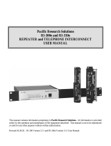
ENDUSER
INSTRUCTIONS
Receivers:
ED-TG2-RX101-EN-v05
Language: English (original)
R4-26, R4-28,
R4-41, R4-43

©Tele-Radio i Lysekil AB
August Barks gata 30A
SE-421 32 Västra Frölunda
Sweden
Phone: +46 (0)31 748 54 60

Enduser instructions│R4│
CHAPTER 1: INTRODUCTION 4
1.1About this document 6
1.2About Tiger TG2 systems 7
CHAPTER 2: SAFETY 8
2.1Warnings & restrictions 8
CHAPTER 3: TECHNICAL DATA 11
3.1Receiver specifications 11
3.2Current consumption 12
CHAPTER 4: PRODUCT DESCRIPTION 14
4.1Receiver description 14
4.2Mechanical installation 16
CHAPTER 5: STATUS AND ERROR INDICATIONS 18
5.1Function LEDs indication in normal operation 18
5.2CANopen run status 19
5.3CANopen error status 19
5.4Fatal error indications and error code messages 20
5.5Show digital input status on the transmitter 21
CHAPTER 6: OPERATION 23
6.1General information 23
6.2Relay functions 23
CHAPTER 7: WARRANTY, SERVICE, REPAIRS, AND MAINTENANCE 24
CHAPTER 8: REGULATORY INFORMATION 25
8.1Europe 25
8.2North America 25
8.3Brazil 28
ANNEX A: INDEX 29
ED-TG2-RX101-EN-v05 3

Enduser instructions│R4│Chapter 1: Introduction
CHAPTER 1: INTRODUCTION
Thank you for using a Tele Radio product
READ ALL INSTRUCTIONS AND WARNINGS CAREFULLY BEFORE OPERATING
THE PRODUCTS.
These End user instructions have been published by Tele Radio and are not subject
to any guarantees. The End user instructions may be withdrawn or revised by Tele
Radio at any time and without further notice. Corrections and updates will be
added to the latest version of the manual. Always download the End user
instructions from our website, www.tele-radio.com, for the latest available version.
Keep the safety instructions for future reference.
IMPORTANT! These instructions are intended for end users. The instructions can be
printed and handed to end user.
Tele Radio remote controls are often built into wider applications. This
documentation is not intended to replace the determination of suitability or
reliability of the product for specific user applications and should not be used for
this purpose. It is the responsibility of any such users or integrators to perform the
appropriate and complete risk analysis, evaluation and testing of the products with
respect to the relevant specific application or use. Tele Radio shall not be
responsible or liable for misuse of the information contained herein.
Always refer to the applicable local regulations for installation and safety
requirements relating to cranes, hoists, material handling applications, lifting
equipment, industrial machinery, and/or mobile hydraulic applications using Tele
Radio products, e.g.:
lapplicable local and industrial standards and requirements,
lapplicable occupational health and safety regulations,
lapplicable safety rules and procedures for the factory where the equipment
is being used,
luser and safety manuals or instructions of the manufacturer of the
equipment where Tele Radio remote control systems are installed.
Tele Radio End user instructions do not include or address the specific instructions
and safety warnings of the end product manufacturer.
4 ED-TG2-RX101-EN-v05


Enduser instructions│R4│Chapter 1: Introduction
1.1About this document
Before installing or operating the product, read the corresponding documentation
carefully.
Tele Radio's product range is composed of transmitters, receivers, and accessories
intended for use together as a system.
These End user instructions cover general safety issues, main technical
specifications, and standard operating instructions. Images shown in this document
are for illustrative purposes only.
Please report any error or omission in this document, as well as any improvement
or amendment suggestion to td@tele-radio.com.
1.1.1COPYRIGHT
Information in this document is subject to change without notice. No part of this
publication may be reproduced, stored in a retrieval system, or transmitted in any
form or by any means, electronic, photographic, mechanical (including
photocopying), recording or otherwise for any purpose other than the purchaser's
personal use without the written permission of Tele Radio.
1.1.2TERM AND SYMBOL DEFINITIONS
The capitalized terms and symbol used herein shall have the following meaning:
lWARNING: indicates a hazardous situation which, if not avoided, could result
in death or serious injury.
lCAUTION: indicates a hazardous situation which, if not avoided, will result in
minor or moderate injury.
lIMPORTANT: is used for information that requires special consideration.
lNOTE: is used to address practices not related to physical injury.
This symbol is used to call attention to safety messages that would be
assigned the signal words "WARNING"or "CAUTION".
6 ED-TG2-RX101-EN-v05

Enduser instructions│R4│Chapter 1: Introduction
1.2About Tiger TG2 systems
The Tiger TG2 product range is composed of transmitters and receivers intended for
use together as a system in complex lifting applications such as cranes, OHT cranes
and electric hoists or mobile applications.
1.2.1ABOUT R4 RECEIVERS
R4 receivers have simplex communication with support for duplex. They are
compatible with all T9, T11, T12, T14 and T15 transmitters within the same frequency
range.
Overview of available models
• 4 3 3 M H z f r e q u e n c y r a n g e
Casing type Main board Expansion boards Bus system
High Low 12–24 V AC/DC,
48–230 V AC
7 relays
10-relay ADIO
(4 relays)
CAN/
J1939
R4-01 ●–●– – –
R4-06 ●–● ● – –
R4-26 – ● ● – – ●(CANopen)
R4-36 ●–●–●–
R4-41 – ● ● – – ●(J1939)
●Standard – Not available
• 9 1 5 M H z f r e q u e n c y r a n g e
Casing type Main board Expansion boards Bus system
High Low 12–24 V AC/DC,
48–230 V AC
7 relays
10-relay ADIO
(4 relays)
CAN/
J1939
R4-03 ●–●– – –
R4-08 ●–● ● – –
R4-28 – ● ● – – ●(CANopen)
R4-38 ●–●–●
R4-43 – ● ● – – ●(J1939)
●Standard – Not available
ED-TG2-RX101-EN-v05 7

Enduser instructions│R4│Chapter 2: Safety
CHAPTER 2: SAFETY
2.1Warnings & restrictions
Carefully read through the following safety instructions before
proceeding with the installation, configuration, operation, or
maintenance of the product. Failure to follow these warnings could
result in death or serious injury.
This product must not be operated without having read and understood the
Enduser instructions and having received the appropriate training. The purchaser
of this product has been instructed how to handle the system safely. The following
information is intended for use as a complement to applicable local regulations
and standards.
IMPORTANT! Tele Radio remote controls are often built into wider applications.
These systems should be equipped with:
• a wired emergency stop where necessary
• a brake
• an audible or visual warning signal
2.1.1OPERATION
This radio system must not be used in areas where there is a risk of
explosion.
This equipment is not suitable for use in locations where children are
likely to be present.
Only qualified personnel should be permitted to access the transmitter
and operate the equipment.
8 ED-TG2-RX101-EN-v05

Enduser instructions│R4│Chapter 2: Safety
lAlways follow operating and maintenance instructions as well as all
applicable safety procedures and requirements.
lDo not open the receiver encapsulation unless you are qualified.
lYou must satisfy the age requirements in your country for operating
the equipment.
lIt is strictly prohibited to operate the equipment under the influence
of drugs, alcohol and/or medications.
lAlways test the transmitter stop button before operating it. Press
the stop button then twist and pull it out. This test should be done
on each shift, without a load.
lNever use a transmitter if the stop button is mechanically
damaged.Contact your supervisor or representative for service
immediately.
lNever leave the transmitter unattended.
lAlways switch the transmitter off when not in use. Store in a safe
place.
lKeep a clear view of the work area at all times.
2.1.2MAINTENANCE
Before maintenance intervention on any remote controlled equipments:
• always remove all electrical power from the equipment.
• always follow lockout procedures.
lKeep the safety information for future reference. Always download the
Enduser instructions from our website, www.tele-radio.com, for the latest
available version.
lIf error messages are shown, it is very important to find out what caused
them. Contact your representative for help.
lThe functionality of the stop button should be tested at least after every 200
hours’ use.
lIf the stop button is mechanically damaged, do not use the transmitter.
Contact your supervisor or representative for service immediately.
lDo not try to open the encapsulation.
lAlways contact your representative for service and maintenance work on the
product.
lKeep contacts and antennas clean.
lWipe off dust using a clean, slightly damp cloth.
lNever use cleaning solutions.
ED-TG2-RX101-EN-v05 9

Enduser instructions│R4│Chapter 2: Safety
lCheck the encapsulation, foils and cable for damages every day. If you use
the product although the encapsulation or foil is damaged, moisture can
cause serious damage to the electronics.
10 ED-TG2-RX101-EN-v05

Enduser instructions│R4│Chapter 3: Technical data
CHAPTER 3: TECHNICAL DATA
3.1Receiver specifications
3.1.1433 MHZ
R4-01 R4-06 R4-36 R4-26 R4-41
Input power 12–24V AC/DC, 48–230VAC, 50–60Hz, max. 2A
Number of stop relays 2 (potential free*, 16A, 250VAC)1
Number of relays 7 17 11 7 7
(potential free*, 10A, 250VAC)
Relay functionality Momentary, latching,
interlocking Analog Momentary, latching,
interlocking
Number of digital inputs 2 10 5 2 2
Number of digital outputs – – 12 – –
Number of transistor
outputs 1
Bus system – – Analog CANopen CAN/ J1939
Connector Cable gland M25x1.5 Cable gland M20x1.5
Radio type Low IFtopology
Radio frequency band 433.075–434.775 MHz
Number of channels 69 (channels 1–69)
Radio communication Simplex (default), support for duplex
Radio frequency output
power EIRP2: <10dBm (10mW)
Max. number of registered
transmitters 15
Antenna 1 BNC connector for external antenna
Safety level EN 61508 SIL3 and EN ISO 13849 PLe (Stop function)
IP code IP66
Operating temperature -20…+55°C / -4…+130°F
Dimensions (LxWxH) 176x160x75mm /
6.9x6.3x2.9in 176x160x52mm /
6.9x6.3x2in
Weight (typical) 800g /
1.8lbs 950g / 2.1lbs 800g / 1.8lbs
3.1.2915 MHZ
R4-03 R4-08 R4-38 R4-28 R4-43
Input power 12–24V AC/DC, 48–230VAC, 50–60Hz, max. 2A
1Maximum load is indicated for resistive load only.
2Equivalent isotropic radiated power
ED-TG2-RX101-EN-v05 11

Enduser instructions│R4│Chapter 3: Technical data
R4-03 R4-08 R4-38 R4-28 R4-43
Number of stop relays 2 (potential free*, 16A, 250VAC)
Number of relays 7 17 11 7 7
(potential free*, 10A, 250VAC)
Relay functionality Momentary, latching,
interlocking Analog Momentary, latching,
interlocking
Number of digital inputs 2 10 5 2 2
Number of digital outputs – – 12 – –
Number of transistor
outputs 1
Bus system – – Analog CANopen CAN/ J1939
Connector Cable gland M25x1.5 Cable gland M20x1.5
Radio type Low IFtopology
Radio frequency band 903.0125–926.9875 MHz
Number of frequency
banks 15 (banks 1–15)
Radio communication Simplex (default), support for duplex
Radio frequency output
power EIRP1: <0dBm (1mW)
Max. number of registered
transmitters 15
Antenna 1 RP-SMA connector for external antenna
Safety level EN 61508 SIL3 and EN ISO 13849 PLe (Stop function)
IP code IP66
Operating temperature -20…+55°C / -4…+130°F
Dimensions (LxWxH) 176x160 x75mm /
6.9x6.3x2.9in 176x160x53mm /
6.9x6.3x2.1in
Weight (typical) 800g /
1.8lbs 950g / 2.1lbs 800g / 1.8lbs
* Potential free means that a supply voltage is needed to get voltage out of a relay
(e.g. via the included connection comb).
3.2Current consumption
Input
power
R4-01, R4-03,
R4-26, R4-28,
R4-41, R4-43
R4-06, R4-08 R4-36, R4-38
Min.* Max.** Min.* Max.** Min.* Max.**
12VAC 0.13 A 0.33 A 0.13 A 0.40 A 0.20 A 0.51 A
24VAC 0.06 A 0.13 A 0.06 A 0.24 A 0.09 A 0.20 A
48VAC 0.04 A 0.09 A 0.04 A 0.16 A 0.06 A 0.14 A
1Equivalent isotropic radiated power
12 ED-TG2-RX101-EN-v05

Enduser instructions│R4│Chapter 3: Technical data
Input
power
R4-01, R4-03,
R4-26, R4-28,
R4-41, R4-43
R4-06, R4-08 R4-36, R4-38
Min.* Max.** Min.* Max.** Min.* Max.**
115VAC 0.02 A 0.04 A 0.02 A 0.07 A 0.02 A 0.06 A
230VAC 0.01 A 0.03 A 0.01 A 0.04 A 0.01 A 0.04 A
12VDC 0.13 A 0.28 A 0.13 A 0.52 A 0.18 A 0.45 A
24VDC 0.06 A 0.25 A 0.06 A 0.14 A 0.09 A 0.22 A
*Minimum current consumption = Receiver powered, no active relays, no radio
session established.
**Maximum current consumption = Receiver powered, all relays on the receiver
active, radio session established.
ED-TG2-RX101-EN-v05 13

Enduser instructions│R4│Chapter 4: Product description
CHAPTER 4: PRODUCT DESCRIPTION
The pictures shown in this chapter are for illustrative purposes only.
4.1Receiver description
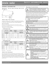
4.1.1R4-01, R4-06, R4-36
1. Cable gland M25x1.5 2. BNC connector for external antenna*
4.1.2R4-03, R4-08, R4-38
1. Cable gland M25x1.5 2. RP-SMA connector for external antenna*
*Antenna in option. Must be purchased separately.
14 ED-TG2-RX101-EN-v05

Enduser instructions│R4│Chapter 4: Product description
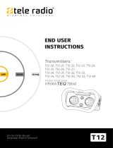
4.1.3R4-26, R4-41
1. Cable gland M25x1.5 2. BNC connector for external antenna*
4.1.4R4-28, R4-43
1. Cable gland M25x1.5 2. RP-SMA connector for external antenna*
*Antenna in option. Must be purchased separately.
ED-TG2-RX101-EN-v05 15

Enduser instructions│R4│Chapter 4: Product description
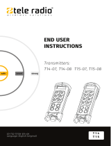
4.2Mechanical installation
NOTE: For mounting on a wall or equipment, use 4 M5x30mm screws or equivalent
fastening method.
4.2.1R4-01, R4-06, R4-36 (HIGH CASING, BNC CONNECTOR)
4.2.2R4-03, R4-08, R4-38 (HIGH CASING, RP-SMA CONNECTOR)
16 ED-TG2-RX101-EN-v05

Enduser instructions│R4│Chapter 4: Product description
4.2.3R4-26, R4-41 (LOW CASING, BNC CONNECTOR)
4.2.4R4-28, R4-43 (LOW CASING, RP-SMA CONNECTOR)
ED-TG2-RX101-EN-v05 17

Enduser instructions│R4│Chapter 5: Status and error indications
CHAPTER 5: STATUS AND ERROR INDICATIONS
5.1Function LEDs indication in normal operation
LED Color Off On Flashing Indicates
1 Red
●No transmitter is registered.
●One or more transmitters are
registered.
2 Yellow ●No transmitter is logged in.
●One transmitter is logged in.
3 Green ●Receiving valid RS485 data.
4 Orange
●SIL conformity (settings in the safety
CPUs are conform with SIL3).
●SIL error (settings in the safety CPUs
are not conform with SIL3).
5 Red
●
Automatic frequency control
processing.
Signal is not locked on the transmitter.
●Automatic frequency control fine-tuned.
Signal is locked on the transmitter.
●The receiver is scanning frequency
6 Yellow ●Receiving valid sync word.
7 Green ●Receiving valid radio packet.
18 ED-TG2-RX101-EN-v05

Enduser instructions│R4│Chapter 5: Status and error indications
5.2CANopen run status
NOTE: Applies to receiver models: R4-26, R4-28, R4-41, R4-43
Colour On Flickering
together with
Error LED
Single flash Blinking
Green Operational
state LSS Stopped state Pre-operational
state
CANopen
communication states
Description
Operational State for process data transmission.
LSS LSS services in progress
Stopped Except for node guarding or heartbeat messages, a node
cannot transmit or receive any other messages in this
state.
Pre-operational State for the configuration of CANopen devices. PDO
communication is not possible in this state.
5.3CANopen error status
Colour On Flickering
together with
Error LED
Single flash Blinking Triple flash
Red Bus off LSS Warning
limit
reached
Error
control
event
Sync error
Contact your representative for assistance.
ED-TG2-RX101-EN-v05 19

Enduser instructions│R4│Chapter 5: Status and error indications
5.4Fatal error indications and error code
messages
Fatal errors are indicated by function LEDs 1–7, which are all flashing at the same
time. Each fatal error is identified by a code indicated by relay LEDs 1–5 (or by LEDs
17, 11–14 on the relay expansion board). Contact your representative for assistance.
●: LED is lit. ○: LED is off.
Relay LED1/LED2Description
Relay
LED1/
LED17
(red)
Relay
LED2/
LED11
(red)
Relay
LED3/
LED12
(red)
Relay
LED4/
LED13
(red)
Relay
LED5/
LED14
(red)
Invalid/ missing production data
in the CPUs
Incompatible software in the
CPUs
Bad settings data
No reply from CPU1 or CPU2
Receiver in test mode (no error)
Initialization of the radio module
failed
Incompatible expansion board*
No CAN expansion board found**
SIL error reported from CPU1 or
CPU2
Incompatible radio module
LML fatal error
Missing or bad binDat
No binDat ID in binDat
Wrong target software ID in
binDat
Wrong target software version in
binDat
Wrong cclml version in binDat
Buffer is full
* R4-06, R4-08 models only.
** R4-26, R4-28, R4-41, R4-43 models only.
1On the base boardand the analog exp. board.
2On the relay expansion board .
20 ED-TG2-RX101-EN-v05
/