Page is loading ...

safe smart strong
R2
R2-01 with transmitters T1-01,
T1-02, T1-03
INSTALLATION
INSTRUCTIONS
Receiver
IM-LX-RX101-EN-v02
Language: English (original)

©Tele-Radio i Lysekil AB
Datavägen 21
SE-436 32 Askim
Sweden
Phone: +46 (0)31 748 54 60

Installation instructions│R2│
CONTENTS
CHAPTER 1: INTRODUCTION 4
1.1About this document 6
1.2About Lynx systems 7
CHAPTER 2: SAFETY 10
2.1Warnings & restrictions 10
CHAPTER 3: TECHNICAL DATA 13
3.1Stationary unit specifications 13
3.2Current consumption 13
CHAPTER 4: PRODUCT GENERAL DESCRIPTION 14
4.1Stationary unit description 14
4.2Mechanical installation 15
CHAPTER 5: BOARD DESCRIPTION 17
5.1Base board 17
CHAPTER 6: STATUS AND ERROR INDICATIONS ON THE STATIONARY UNIT 19
CHAPTER 7: HAND UNITS 20
7.1Battery precautions 20
7.2Hand unit description – T1-01, T1-02,T1-03 21
7.3Change the batteries 23
7.4Status and error indications on the hand unit 24
CHAPTER 8: WARRANTY, SERVICE, REPAIRS, AND MAINTENANCE 25
CHAPTER 9: REGULATORY INFORMATION 26
9.1Europe 26
9.2North America 27
ANNEX A: IMPLEMENTATION SPECIFICATIONS– LYNX (IN ENGLISH) 29
A.1Modbus Commands 29
A.2Register Map 29
ANNEX B: SETTINGS DOCUMENTS 35
ANNEX C: INDEX 36
IM-LX-RX101-EN-v02 3

Installation instructions│R2│Chapter 1: Introduction
CHAPTER 1: INTRODUCTION
Thank you for purchasing a Tele Radio product
READ ALL INSTRUCTIONS AND WARNINGS CAREFULLY BEFORE MOUNTING,
INSTALLING, CONFIGURING ANDOPERATING THE PRODUCTS.
These Installation instructions have been published by Tele Radio and are not
subject to any guarantees. The Installation instructions may be withdrawn or
revised by Tele Radio at any time and without further notice. Corrections and
updates will be added to the latest version of the manual. Always download the
Installation instructions from our website, www.tele-radio.com, for the latest
available version. Keep the safety instructions for future reference.
IMPORTANT! These instructions are intended for installers and authorized service
and distribution centers. The instructions containing information about the
installation and configuration of the radio remote control unit on the machine are
NOT intended to be passed on to the end user. Only information that is needed to
operate the machine correctly by radio remote control may be passed on to the end
user.
Tele Radio remote controls are often built into wider applications. This
documentation is not intended to replace the determination of suitability or
reliability of the product for specific user applications and should not be used for
this purpose. It is the responsibility of any such users or integrators to perform the
appropriate and complete risk analysis, evaluation and testing of the products with
respect to the relevant specific application or use. Tele Radio shall not be
responsible or liable for misuse of the information contained herein.
Always refer to the applicable local regulations for installation and safety
requirements relating to cranes, hoists, material handling applications, lifting
equipment, industrial machinery, and/or mobile hydraulic applications using Tele
Radio products, e.g.:
lapplicable local and industrial standards and requirements,
lapplicable occupational health and safety regulations,
lapplicable safety rules and procedures for the factory where the equipment
is being used,
luser and safety manuals or instructions of the manufacturer of the
equipment where Tele Radio remote control systems are installed.
4 IM-LX-RX101-EN-v02

Installation instructions│R2│Chapter 1: Introduction
Tele Radio Installation instructions do not include or address the specific
instructions and safety warnings of the end product manufacturer.
Tele Radio products are covered by a warranty against material, construction, or
manufacturing faults. See "Chapter 8: Warranty, service, repairs, and maintenance".
IM-LX-RX101-EN-v02 5

Installation instructions│R2│Chapter 1: Introduction
1.1 About this document
Every care has been taken in the preparation of this manual. Please inform Tele
Radio of any inaccuracies or omissions.
These installation instructions cover general safety issues, main technical
specifications, standard installation, configuration instructions and battery
information. Images shown in this document are for illustrative purposes only.
1.1.1TERM AND SYMBOL DEFINITIONS
The capitalized terms and symbol used herein shall have the following meaning:
lWARNING: indicates a hazardous situation which, if not avoided, could result
in death or serious injury.
lCAUTION: indicates a hazardous situation which, if not avoided, will result in
minor or moderate injury.
lIMPORTANT: is used for information that requires special consideration.
lNOTE: is used to address practices not related to physical injury.
This symbol is used to call attention to safety messages that would be
assigned the signal words "WARNING"or "CAUTION".
6 IM-LX-RX101-EN-v02

Installation instructions│R2│Chapter 1: Introduction
1.2About Lynx systems
Lynx systems are composed of a stationary unit (receiver), a hand unit (transmitter)
and a master unit (PC).
The communication between the master device and the Lynx system requires to
write a software application. Configuration is done via Modbus protocol (see "Annex
A: Implementation Specifications– Lynx (in English)" for more details).
1.2.1THE HAND UNIT
The transmitter uses duplex communication and works in continuous mode.
There are three models available: with 3, 6 or 8 buttons.
1.2.2THESTATIONARY UNIT
The receiver uses duplex communication and works in continuous mode.
It can use RS232 and RS485 for communication with the master unit and has two
open collector outputs and two digital inputs.
1.2.3MASTERUNIT
Can be e.g. a PC or a PLC. The master unit must be connected to the receiver with a
serial cable (cross over/null modem RS232 cable). The system is based on Modbus,
a widely used, open serial communication protocol. Transmission speed is approx.
19 200 bits per second. It is possible to choose between RS232 or RS485 for
communication with the receiver.
IM-LX-RX101-EN-v02 7

Installation instructions│R2│Chapter 1: Introduction
1.2.4GENERAL INFORMATION ABOUT MODBUS PROTOCOL
To enable communication between computerized systems, a protocol is required to
define the rules of communication. Modbus is one of the most common protocols
used for transmitting information between electronic devices over serial lines.
Master & slaves
The device requesting the information is called the Master. The devices supplying
information are called the slaves.
In a standard Modbus network, there is one Master and up to 247 slaves, each with
a unique address from 1 to 247.
Modbus messages
Modbus is transmitted over serial cables between devices. The data is sent as
series of ones and zeroes, called bits. Each bit is sent as a voltage. Zeroes are sent
as positive voltages and ones are sent as negative voltages.
When the master requests data, the first byte it sends is the slave address. This way
the slave will know whether to ignore the message or not, right after receiving the
first byte.
Error check
CRC (Cyclic Redundancy check) is 2 bytes added to the end of every Modbus
message for error detection. Every byte in the message is used to calculate the CRC.
When receiving a message, the receiving device calculates the CRC and compares it
to the CRC from the sending device. If even one bit in the message is received
incorrectly, an error will be reported.
1.2.5SERIAL COMMUNICATION
NOTE: Using twisted or shielded cables is recommended with RS232 and RS485.
RS232
An asynchronous point-to-point standard that enables a variety of ways to
communicate with PCs. The transmissions seldom exceed 100 feet/ 30 m.
RS485
A asynchronous multi-point standard using differential signaling for applications
where it's important to reduce wiring expenses, and achieve longer line lengths.
8 IM-LX-RX101-EN-v02

Installation instructions│R2│Chapter 1: Introduction
1.2.6INPUTS/ OUTPUTS
Open collectors (OC)
A lower or higher voltage than the input power supply can be used (up to 24V DC).
Can be used to interface devices that have different operating logic voltage levels,
or to control external circuitry that requires a higher voltage level ( e.g. a 12 V
relay).
Open collectors are controlled by the master application. More than one open-
collector output can be connected to a single line. See "5.1 Base board" for more
details)
Digital inputs
DI can be used for receiving input from the master application. A switch, or a micro
switch, can be connected (see " Wiring example for the digital inputs" for more
details). Maximum input voltage to the digital inputs is +3.3 VDC referred to GND.
IM-LX-RX101-EN-v02 9

Installation instructions│R2│Chapter 2: Safety
CHAPTER 2: SAFETY
2.1Warnings & restrictions
Carefully read through the following safety instructions before
proceeding with the installation, configuration, operation, or
maintenance of the product. Failure to follow these warnings could
result in death or serious injury.
This product must not be operated without having read and understood the
Installation instructions, the specific technical documentation (for customized
systems), and having received the appropriate training. The purchaser of this
product has been instructed how to handle the system safely. The following
information is intended for use as a complement to applicable local regulations
and standards.
IMPORTANT! Tele Radio remote controls are often built into wider applications.
These systems should be equipped with:
• a wired emergency stop where necessary
• a brake
• an audible or visual warning signal
2.1.1INSTALLATION AND COMMISSIONING
IMPORTANT! Only licensed or qualified personnel should be permitted to install
the product.
This radio system must not be used in areas where there is a risk of
explosion.
Always switch off all electrical power from the equipment before
installation procedure.
When the equipment controlled by the receiver's standard relays is
connected via the stop relays, make sure that the maximum current
through the stop relays is still within the specifications. Contact your
representative for assistance.
10 IM-LX-RX101-EN-v02

Installation instructions│R2│Chapter 2: Safety
RISK OF UNINTENDED EQUIPMENT OPERATION
Only transmitters that are intended for use should be registered in the
receiver.
Failure to follow these instructions could result in death, serious injury,
or equipment damage.
RISK OF ELECTRIC SHOCK
The receiver must only be opened by qualified installers or authorized
personnel.
Make sure the power supply is switched off before opening the receiver.
Failure to follow these instructions could result in death, serious injury,
or equipment damage.
lThe receiver must be securely attached and located where it will
not be hit by e.g. any moving parts.
lDo not install the product in areas affected by strong vibrations
lCable glands and vent plugs must face downwards to prevent water
ingress.
lEnsure that the power supply is connected to the correct terminals.
lEnsure that flexible cords and cables are not damaged through
friction or stress.
lDo not use damaged cables.
lEnsure cables and connectors do not hang loose.
lThe receiver is designed to withstand normal weather conditions but should
be protected from extreme conditions.
lInstall the receiver in a location where the LEDs are easily visible.
lMake sure to install available accessories inside or on the receiver before
permanently installing the receiver. A permanent installation of the product
must include fuse protection of the equipment and cables against short
circuits.
2.1.2OPERATION
Only qualified personnel should be permitted to access the transmitter
and operate the equipment.
IM-LX-RX101-EN-v02 11

Installation instructions│R2│Chapter 2: Safety
lMake sure that the user satisfies the age requirements in your
country for operating the equipment.
lMake sure that the user is not under the influence of drugs, alcohol
and medications.
lMake sure that the user knows and follows operating and
maintenance instructions as well as all applicable safety
procedures and requirements.
The user should:
lAlways test the transmitter stop button before operating it.This
test should be done on each shift, without a load.
lNever use a transmitter if the stop button is mechanically
damaged.Contact your supervisor or representative for service
immediately.
lNever leave the transmitter unattended.
lAlways switch the transmitter off when not in use. Store in a safe
place.
lKeep a clear view of the work area at all times.
2.1.3MAINTENANCE
Before maintenance intervention on any remote controlled equipments:
• always remove all electrical power from the equipment.
• always follow lockout procedures.
lKeep the safety information for future reference. Always download the
Installation instructions from our website, www.tele-radio.com, for the latest
available version.
lIf error messages are shown, it is very important to find out what caused
them. Contact your representative for help.
lKeep contacts and antennas clean.
lWipe off dust using a clean, slightly damp cloth.
lNever use cleaning solutions.
lCheck the encapsulation, foils and cable for damages. If the encapsulation or
foil is damaged, moisture can cause serious damage to the electronics.
12 IM-LX-RX101-EN-v02

Installation instructions│R2│Chapter 3: Technical data
CHAPTER 3: TECHNICAL DATA
3.1Stationary unit specifications
R2-01
Power supply 5–24V DC
Number of digital inputs 2
Number of digital outputs 2 (open collector)
Radio frequency band 2405–2480 MHz
Number of channels 16 (channels 11–26)
Channel separation 5MHz
Radio communication Duplex
Radio frequency output power EIRP1 < 0dBm (1mW)
Max. number of registered transmitters 16
IP code IP65
Operating temperature -20…+55°C / -4…+130°F
Dimensions 54 x 96 x 37mm
Weight (typical) 130 g
Antenna Internal antenna
Bus system/com. protocols RS232,RS485
Compatible transmitter(s) T1-01, T1-02, T1-03
3.2Current consumption
Input power R2-01
5VDC 30mA
12V DC 30mA
24V DC 16mA
1Equivalent isotropic radiated power
IM-LX-RX101-EN-v02 13

Installation instructions│R2│Chapter 4: Product general description
CHAPTER 4: PRODUCT GENERAL DESCRIPTION
NOTE: The pictures shown in this chapter are for illustrative purposes only.
Depending on the configuration, the actual product appearance may differ from
the basic model used for reference.
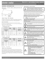
4.1Stationary unit description
1. Cable glands (M20x1.5)
14 IM-LX-RX101-EN-v02

Installation instructions│R2│Chapter 4: Product general description
4.2Mechanical installation
IM-LX-RX101-EN-v02 15

Installation instructions│R2│Chapter 4: Product general description
4.2.1INSTALLATION PRECAUTIONS
RISK OF ELECTRIC SHOCK
The receiver must only be opened by qualified installers or authorized
personnel.
Make sure the power supply is switched off before opening the receiver.
Failure to follow these instructions could result in death, serious injury,
or equipment damage.
IMPORTANT! Only authorized personnel should install the product.
Only correct installation complies with the safety levels for the product.
lA permanent installation of the receiver must include fuses in order to
protect the equipment and cables from short circuit.
lThe receiver must be installed vertically, on a flat and rigid surface, with the
cable at the bottom.
lInstall the receiver in a location where it is easily visible.
Mount the receiver in a location where the LEDs and buttons inside the
receiver are easily visible and accessible, e.g. for troubleshooting operations.
lConsider the wiring limitation and the radio communication limitation to
choose the receiver location.
lEnsure no obstacle is impairing the radio communication performance
between the receiver and the transmitter.
lThe receiver must not be installed inside closed metal containers.
lMake sure any accessories inside or on the receiver are installed before
permanently installing the receiver.
lTest the equipment before installing the receiver permanently.
16 IM-LX-RX101-EN-v02

Installation instructions│R2│Chapter 5: Board description
CHAPTER 5: BOARD DESCRIPTION
NOTE: The pictures shown in this chapter are for illustrative purposes only.
Depending on the configuration, the actual product appearance may differ from
the basic model used for reference.
RISK OF ELECTRIC SHOCK
The receiver must only be opened by qualified installers or authorized
personnel.
Make sure the power supply is switched off before opening the receiver.
Failure to follow these instructions could result in death, serious injury,
or equipment damage.
IMPORTANT! Only experienced electronic technicians should add and map
expansion boards and inputs/outputs.
5.1Base board
1. Terminal block for input power and
communication
2. LED 1 (green)
3. LED 2 (yellow)
4. LED 3 (red)
5. Connector for digital
inputs
6. Programming contact
IM-LX-RX101-EN-v02 17

Installation instructions│R2│Chapter 5: Board description
5.1.1TERMINAL BLOCK FOR INPUT POWER AND
COMMUNICATION
Pin Description
1. RS232 Transmitter
2. GND
3. Receiver
4. RS485 Port A
5. Port B
6. Open-collector outputs Open collector 1*
7. Open collector 2*
8. Input power + 5–24VDC
9. GND
*Not implemented.
5.1.2CONNECTOR FOR DIGITAL INPUTS
Pin Description
1. DI 1
2. DI 2
3. GND
Wiring example for the digital inputs
NOTE: Maximum input voltage to the digital inputs is +3.3 VDC referred to GND.
18 IM-LX-RX101-EN-v02

Installation instructions│R2│Chapter 6: Status and error indications on the
stationary unit
CHAPTER 6: STATUS AND ERROR INDICATIONS
ON THE STATIONARY UNIT
: LED is lit. : LED is off.
²: LED is blinking (red); : LED is blinking (yellow);
LED 1
(green)
LED 2
(yellow)
LED 3
(red)
Indicates
○ No power to the receiver
● Receiver is powered up
●●The stationary unit is in registering mode
(activated by a 'register' command from the
customer host system). The unit will not respond
to any Modbus commands while in registering
mode. The unit stays in registering mode for 10 s.
Modbus packages sent to this unit are being
received on either RS232 or RS485.
²Radio packages are being sent and received on
the same channel as the stationary unit.
²
with 2s
interval
The unit cannot read the start-up information,
such as ID code. Contact your representative for
assistance.
²
with 4 s
interval
The flash memory may be damaged. contact your
representative for assistance.
IM-LX-RX101-EN-v02 19

Installation instructions│R2│Chapter 7: Hand Units
CHAPTER 7: HAND UNITS
7.1Battery precautions
Carefully read through the following safety instructions and warnings before using,
charging or disposing of the batteries.
Batteries contain flammable substances such as lithium or other organic solvents,
which may result in overheating, rupture or combustion. Failure to read and follow
the below instructions may result in fire, personal injury and damage to property if
charged or used improperly.
7.1.1HANDLING AND STORAGE
nRisk of explosion if battery is replaced with a battery of an incorrect type.
nDo not short circuit, disassemble, deform or heat batteries.
nNever attempt to charge a visibly damaged or frozen battery.
nDo not use or charge the battery if it appears to be leaking, deformed or
damaged in any way.
nDo not solder directly onto batteries.
nDo not leave the battery in the charger once it is fully charged.
nStore in a cool location. Keep batteries away from direct sunlight, high
temperature, and high humidity.
nImmediately discontinue use of the battery if, while using, charging, or storing
the battery, the battery emits an unusual smell, feels hot, changes color,
changes shape, or appears abnormal in any other way.
nKeep batteries out of reach of small children. Should a child swallow a battery,
consult a physician immediately.
7.1.2DISPOSAL
When discarding batteries, insulate the + and - terminals of batteries with
insulating/ masking tape.
nDo not place multiple batteries in the same plastic bag.
nDo not incinerate or dispose of batteries in fire.
nDo not place used batteries in the household waste. Dispose of used batteries
in accordance with the applicable regulations and legal requirements.
nBatteries that have been disposed of incorrectly may short circuit, causing them
to become hot, burst or ignite.
20 IM-LX-RX101-EN-v02
/