Page is loading ...

Pacific Research Solutions
RI-300e and RI-310e
REPEATER and TELEPHONE INTERCONNECT
USER MANUAL
This manual contains information proprietary to
Pacific Research Solutions
. All information is provided
solely for the operation and maintenance of the equipment described. This manual is not to be reproduced
or used for any other purpose without written authorization.
Revised 02.28.02 – RI-300 Version 2.11 and RI-300e Version 3.11 User Manual


Pacific Research Solutions RI-300 User Manual
Page i
TABLE OF CONTENTS
SECTION 1
INTRODUCTION ..........................................................................................................1
What is the RI-300(e) Version .............................................................................................................................................1
Overview..............................................................................................................................................................................1
Feature List...........................................................................................................................................................................1
What is an RI-310?...............................................................................................................................................................2
SECTION 2
QUICK START ..............................................................................................................3
UNPACKING THE RI-300.................................................................................................................................................3
MOUNTING THE RI-300 REPEATER CONTROLLER...................................................................................................3
INTERFACE YOUR RECEIVER and TRANSMITTER....................................................................................................3
SETTING AUDIO LEVELS................................................................................................................................................4
Receiver Gain................................................................................................................................................................4
Squelch Level................................................................................................................................................................4
Transmitter Level..........................................................................................................................................................4
OPERATION.......................................................................................................................................................................4
INITIAL SETTINGS...........................................................................................................................................................4
SECTION 3
PROGRAMMING SOFTWARE..................................................................................5
INSTALLATION.................................................................................................................................................................5
OPERATION.......................................................................................................................................................................5
FLASHING the CONTROLLER’S PROGRAM.................................................................................................................5
PROGRAMMING SOFTWARE MENU ............................................................................................................................6
Main Window ...............................................................................................................................................................6
File................................................................................................................................................................................6
Controller......................................................................................................................................................................7
Repeater ........................................................................................................................................................................7
Tone Squelch ................................................................................................................................................................7
Commands.....................................................................................................................................................................7
Triggers.........................................................................................................................................................................8
Telephone......................................................................................................................................................................8
Help...............................................................................................................................................................................8
MACRO EDITING MENU .................................................................................................................................................8
MODEM INTERFACE........................................................................................................................................................9
Vertex Programming Cable to Modem Cable...............................................................................................................9
U.S. Robotics 56K External Modem Set Up...............................................................................................................10
Modem Trouble Shooting...........................................................................................................................................10
SECTION 4
INSTALLATION (RI-300)..........................................................................................11
PROPER TECHNIQUES FOR QUALITY REPEATER AUDIO.....................................................................................11
POWER SUPPLY CONNECTIONS (Pins 1 and 9)..........................................................................................................12
REPEATER RECEIVER AUDIO CONNECTION (Pin 2)...............................................................................................12
REPEATER TRANSMITTER AUDIO CONNECTIONS (Pin 3)....................................................................................12
REPEATER TRANSMITTER PTT OR TRANSMIT KEYING CONNECTION (Pin 4)................................................12
DCS MODULATION (Pin 11)..........................................................................................................................................12
DIGITAL INPUTS (Pins 6, 7 and 8) .................................................................................................................................13
DIGITAL OUTPUTS (Pins 13, 14 and 15) .......................................................................................................................13
ANALOG INPUTS (Pin 5)................................................................................................................................................13
DCS DECODE AND ENCODE SET UP AND OPERATION.........................................................................................13

Pacific Research Solutions RI-300 User Manual
Page ii
SECTION 5
INSTALLATION (RI-310)..........................................................................................15
VXR-5000 FREQUENCY SETUP....................................................................................................................................16
VXR-5000 DEFAULT LED and TX POWER MACROS.................................................................................................16
Initialize VXR-5000DC (DC model)..........................................................................................................................16
Initialize VXR-5000AC (AC model) ..........................................................................................................................16
Changing Transmitter Power Level on the VXR-5000 ......................................................................................................17
VXR-5000 ACCESSORY CONNECTOR “ACC”............................................................................................................18
VXR-5000 INTERFACE BOARD ....................................................................................................................................19
DAC Output access by S-Command 13 ......................................................................................................................19
Bit input accessed by S-Command 45.........................................................................................................................19
Bit output controlled by S-Command 46.....................................................................................................................19
SECTION 6
INSTALLATION (OPTIONS)....................................................................................20
TEMPERATURE SENSOR ..............................................................................................................................................20
INSTALLING DIGITAL VOICE RECORDER................................................................................................................21
INSTALLING AUDIO DELAY (AD-3) ...........................................................................................................................21
INSTALLING THE REMOTE BASE INTERFACE (RBI-3)...........................................................................................22
RBI-3 Jumpers ............................................................................................................................................................22
RBI-3 Connector Pin Out............................................................................................................................................23
SECTION 7
ADJUSTMENTS...........................................................................................................24
SETTING RECEIVER INPUT GAIN (R3).......................................................................................................................24
SETTING SQUELCH GAIN (S-COMMAND 50)............................................................................................................25
SMARTSQUELCH, NORMAL and EXTERNAL SQUELCH OPERATION..............................................................25
ADJUSTING THE REPEATER TRANSMITTER MODULATION (S-COMMAND 12)..............................................26
SECTION 8
OPERATION................................................................................................................27
SYSTEM STATUS INDICATORS...................................................................................................................................27
DTMF COMMAND INPUT..............................................................................................................................................28
TELEMETRY MESSAGES..............................................................................................................................................28
CTCSS DECODE AND ENCODE OPERATION ............................................................................................................29
EVENT SCHEDULER (RI-300, Version 2)......................................................................................................................30
Enable the “CLOCK NOT SET” Courtesy Message ..................................................................................................30
EVENT SCHEDULER (RI-300e, Version 3)....................................................................................................................30
LOCAL MICROPHONE and SPEAKER..........................................................................................................................31
INITIALIZATION PROCEDURE ....................................................................................................................................31
SECTION 9
INITIAL SETTINGS....................................................................................................32
User and System Command Modes....................................................................................................................................32
Command acknowledgment........................................................................................................................................32
DEFAULT USER COMMANDS......................................................................................................................................33
SETTING UP YOUR STATION ID .................................................................................................................................33
SET UP CTCSS/DCS DECODE .......................................................................................................................................36
SET CTCSS/DCS ENCODE..............................................................................................................................................37
YOUR CONTROLLER SERIAL NUMBER.....................................................................................................................37
CHANGING YOUR PASSWORD....................................................................................................................................37
SECTION 10
AUXILIARY BUSS......................................................................................................38
CONNECTING MULTIPLE RI-300 REPEATER CONTROLLERS TOGETHER.........................................................38
Auxiliary Buss and Programming Software................................................................................................................38
Passing System Commands between Controllers........................................................................................................38
SECTION 11
PROGRAMMING........................................................................................................39
PROGRAMMING COMMAND FORMAT......................................................................................................................39
SPEECH READ BACK.....................................................................................................................................................39
PASSWORD ACCESS......................................................................................................................................................39
Forgot your Password?................................................................................................................................................40
Some common Password problems.............................................................................................................................40
Auxiliary Controller Password Access........................................................................................................................40
VALID S-COMMAND and DATA...................................................................................................................................41
RULES FOR LEADING ZEROS IN S-COMMANDS .....................................................................................................41

Pacific Research Solutions RI-300 User Manual
Page iii
SECTION 12
SYSTEM COMMANDS..............................................................................................42
S-Cmd 00
NO OPERATION.........................................................................................................................................43
S-Cmd 01
SYSTEM MODE..........................................................................................................................................43
S-Cmd 02
SUB-AUDIO FILTER ENABLE .................................................................................................................44
S-Cmd 03
USER COMMAND PREFIX SET UP (Palomar Emulation).......................................................................44
S-Cmd 04
REPEATER CARRIER DELAY TIMER ....................................................................................................46
S-Cmd 05
FORCE PTT ON ..........................................................................................................................................46
S-Cmd 06
REPEATER TELEMETRY MODE.............................................................................................................46
S-Cmd 07
ID INTERVAL TIMER................................................................................................................................47
S-Cmd 08
COURTESY MESSAGE TIMER ................................................................................................................47
S-Cmd 09
LED STATUS DISPLAY ON/OFF..............................................................................................................47
S-Cmd 10
REPEATER TIMEOUT TIMER..................................................................................................................48
S-Cmd 11
ALTERNATE COMMAND TERMINATOR..............................................................................................48
S-Cmd 12
ADJUST REPEATER TRANSMITTER AUDIO LEVEL ..........................................................................49
S-Cmd 13
(DAC) Digital to Analog Converter OUTPUT.............................................................................................49
S-Cmd 14
USER AND S-COMMAND CTCSS/DCS TONE PANEL ENABLE.........................................................49
S-Cmd 15
USER COMMAND DECODE ENABLE ....................................................................................................50
S-Cmd 16
DTMF INTER-DIGIT TIME .......................................................................................................................50
S-Cmd 17
DTMF MUTE DELAY TIME......................................................................................................................50
S-Cmd 18
DTMF MUTE CONTROL...........................................................................................................................51
S-Cmd 19
GENERATE DTMF TONES .......................................................................................................................51
S-Cmd 20
TONE PANEL CTCSS TONE and DCS CODE DECODE ENABLE........................................................52
CTCSS Tone and DCS Code Number Table................................................................................................53
S-Cmd 21
SET MASTER and CROSS ENCODE CTCSS TONE or DCS CODE .......................................................53
S-Cmd 22
TONE PANEL CTCSS TONE or DCS CODE ENCODE MODE...............................................................54
S-Cmd 23
INTERNAL FUNCTION CTCSS TONE or DCS CODE ENCODE...........................................................55
S-Cmd 24
SET CTCSS/DCS ENCODE LEVEL...........................................................................................................56
S-Cmd 25
DCS TX/RX DATA POLARITY CONTROL .............................................................................................56
S-Cmd 26
CTCSS and DCS AIR TIME........................................................................................................................56
S-Cmd 27
TONE REMOTE DECODE SET UP...........................................................................................................57
S-Cmd 28
TONE REMOTE MODE and NOTCH FILTER CONTROL......................................................................58
S-Cmd 29
RESET MESSAGES ....................................................................................................................................60
S-Cmd 30
SPEECH MESSAGE EDITOR ....................................................................................................................60
Speech Vocabulary.......................................................................................................................................61
S-Cmd 31
CW MESSAGE EDITOR, TONE GENERATOR COMMANDS...............................................................64
Tone Generator Command Descriptions.......................................................................................................65
Default Messages, Speech and Tone Generator............................................................................................65
Tone Generator Command List.....................................................................................................................66
S-Cmd 32
SET MESSAGE and EVENT TRIGGERS ..................................................................................................68
S-Cmd 33
DIGITAL VOICE RECORDER, EDIT MESSAGE ....................................................................................69
S-Cmd 34
AUXILIARY OUTPUT MODE...................................................................................................................70
S-Cmd 35
AUXILIARY INPUT MODE.......................................................................................................................70
S-Cmd 36
AUXILIARY INPUT CARRIER DELAY TIMER......................................................................................71
S-Cmd 37
REGENERATE and DECODE DTMF TONES FROM the AUXILIARY INPUT.....................................71
S-Cmd 38
MULTIPLE CONTROLLER DATA PROTOCOL and CLONING MODE ...............................................71
S-Cmd 39
RI-300 CONTROLLER UNIT ADDRESS ..................................................................................................72
S-Cmd 40
DELAY TIMER MACRO TRIGGER..........................................................................................................72
S-Cmd 41
RECEIVER INACTIVITY TIMER MACRO TRIGGER............................................................................72
S-Cmd 42
REGULAR INTERVAL MACRO TRIGGER.............................................................................................73
S-Cmd 43
SET CLOCK TIME (RI-300 and RI-310 Version 2 Only)...........................................................................73
S-Cmd 43
SET REAL TIME CLOCK DATE and TIME (RI-300e and RI-310e Only) ...............................................73
S-Cmd 44
SCHEDULER TO TRIGGER A MACRO (RI-300 and RI-310 Version 2 Only)........................................74
S-Cmd 44
SCHEDULER TO TRIGGER A MACRO (RI-300e and RI-310e Version 3 Only) ....................................74
S-Cmd 45
LOGIC INPUTS and INTERNAL FUNCTIONS – STATE CHANGE TRIGGER ....................................75
S-Cmd 46
DIGITAL LOGIC OUTPUT, ON / OFF......................................................................................................75
S-Cmd 47
DIGITAL LOGIC OUTPUT PULSED ON FOR X TIME ..........................................................................75
S-Cmd 48
COUNTER TRIGGER.................................................................................................................................76
S-Cmd 49
DIAL CLICK CONTROL TRIGGER..........................................................................................................76
S-Cmd 50
ADJUST SQUELCH....................................................................................................................................77

Pacific Research Solutions RI-300 User Manual
Page iv
S-Cmd 51
SET SQUELCH MODE...............................................................................................................................77
S-Cmd 52
DETAIL SQUELCH SET UP ......................................................................................................................78
S-Cmd 53
TELEPHONE HYBRID ADJUSTMENT....................................................................................................79
S-Cmd 54
SET KEY-CODE FOR USER COMMANDS..............................................................................................79
S-Cmd 55
PASSWORD FOR S-COMMAND ACCESS...............................................................................................79
S-Cmd 56
PASSWORD FOR TELEPHONE INCOMING RING ACCESS................................................................80
S-Cmd 57
PASSWORD FOR TELEPHONE INCOMING CONTROL ACCESS.......................................................80
S-Cmd 58
REMOTE SOFTWARE RESET ..................................................................................................................80
S-Cmd 59
REMOTE EEPROM INITIALIZE...............................................................................................................81
S-Cmd 60
RESERVED FOR FUTURE COMMAND...................................................................................................81
S-Cmd 61
RESERVED FOR FUTURE COMMAND...................................................................................................81
S-Cmd 62
DEFINING USER COMMANDS................................................................................................................82
S-Cmd 63
MACRO EDITOR, SET STARTING LINE NUMBER POINTER.............................................................84
S-Cmd 64
MACRO EDITOR, INSERT S-COMMANDS ............................................................................................84
S-Cmd 65
CONDITIONAL STATEMENTS (IF / THEN / ELSE)...............................................................................85
S-Cmd 66
READ / WRITE / PUSH / POP SYSTEM DATA .......................................................................................88
S-Cmd 67
CALL MACRO LINE ..................................................................................................................................88
S-Cmd 68
MACRO LINE JUMP ..................................................................................................................................88
S-Cmd 69
EXIT S-COMMAND PROGRAMMING ....................................................................................................89
S-Cmd 70
TELEPHONE OUTGOING CALL MODE .................................................................................................89
S-Cmd 71
TELEPHONE INCOMING CALL MODE..................................................................................................90
S-Cmd 72
TELEPHONE CTCSS/DCS TONE PANEL ENABLE ...............................................................................91
S-Cmd 73
TELEPHONE INCOMING CALL CONTROL TIME-OUT.......................................................................91
S-Cmd 74
INCOMING CALL RING AND COMMAND PASSWORD TIME-OUT..................................................91
S-Cmd 75
TELEPHONE INCOMING RING DELAY.................................................................................................91
S-Cmd 76
TELEPHONE TX RING LIMIT..................................................................................................................92
S-Cmd 77
TELEPHONE OFF-HOOK TIME-OUT TIMER.........................................................................................92
S-Cmd 78
TELEPHONE INACTIVITY ON RECEIVER TIME-OUT TIMER...........................................................92
S-Cmd 79
TELEPHONE INCOMING AGC AUDIO LEVEL .....................................................................................93
S-Cmd 80
FLASH HOOK SWITCH.............................................................................................................................93
S-Cmd 81
TELEPHONE DTMF OR PULSE DIALING SELECT...............................................................................93
S-Cmd 82
TELEPHONE ON/OFF-HOOK AND ACCESS/ACCOUNT CODE..........................................................94
S-Cmd 83
EDIT TELEPHONE ACCESS and ACCOUNT CODES ............................................................................94
S-Cmd 84
TELEPHONE NUMBER AUTO-DIALER .................................................................................................95
S-Cmd 85
SET AN AUTO-DIAL NUMBER FOR USE...............................................................................................95
S-Cmd 86
TELEPHONE NUMBER ACCEPT TABLE ENABLE...............................................................................95
S-Cmd 87
EDIT TELEPHONE NUMBER ACCEPT TABLE.....................................................................................96
S-Cmd 88
TELEPHONE NUMBER REJECT TABLE ENABLE................................................................................96
S-Cmd 89
EDIT TELEPHONE NUMBER REJECT TABLE......................................................................................97
S-Cmd 90
WAIT FOR DIAL TONE TIMER................................................................................................................97
S-Cmd 91
SET TRANSMIT and RECEIVE FREQUENCY.........................................................................................98
S-Cmd 92
SELECT TYPE OF SYNTHESIZED RADIO.............................................................................................98
S-Cmd 93
SET TX OFFSET and BAND LIMITS FOR SYNTHESIZED RADIO......................................................99
S-Cmd 94
SET CHANNEL STEPS...............................................................................................................................99
S-Cmd 95
CHANNEL INCREMENT/DECREMENT..................................................................................................99
S-Cmd 96
GENERIC DATA and DHE RBI-1 INTERFACE .....................................................................................100
S-Cmd 97
RESERVED FOR FUTURE COMMAND.................................................................................................101
S-Cmd 98
RESERVED FOR FUTURE COMMAND.................................................................................................102
S-Cmd 99
USER SCRATCH PAD DATA..................................................................................................................102

Pacific Research Solutions RI-300 User Manual
Page v
SECTION 13
USER COMMANDS and MACROS........................................................................103
DEFINITION of TERMS ................................................................................................................................................104
PROGRAMMING STANDARD USER COMMANDS and MACROS.........................................................................105
Example of programming a standard user command and macro...............................................................................106
Example of programming macro data into the macro data memory:.........................................................................106
Passing S-Commands to Another Controller.............................................................................................................107
Using Conditional Statements (IF-THEN-ELSE) .....................................................................................................107
TELEPHONE COMMANDS ..........................................................................................................................................109
USER S-COMMANDS....................................................................................................................................................109
WILDCARD COMMANDS............................................................................................................................................109
EXITING PROGRAMMING MODE..............................................................................................................................109
SECTION 14
MESSAGES, SPEECH and CW...............................................................................110
PROGRAMMING CW MESSAGES ..............................................................................................................................110
CW Message memory usage.....................................................................................................................................110
CW Messages within a user command macro...........................................................................................................110
Default CW station ID example................................................................................................................................110
Custom tone generator CW message example ..........................................................................................................112
PROGRAMMING SPEECH MESSAGES......................................................................................................................112
Speech Message memory usage................................................................................................................................112
CW Messages within a user command macro...........................................................................................................113
Speech message example..........................................................................................................................................113
EXITING PROGRAMMING MODE..............................................................................................................................114
SECTION 15
TELEPHONE INTERCONNECT ...........................................................................115
TELEPHONE Automatic Gain Control...........................................................................................................................115
DIALING PROCESS.......................................................................................................................................................115
TELEPHONE INCOMING CALLS................................................................................................................................115
TELEPHONE USER COMMANDS...............................................................................................................................116
TELEPHONE INCOMING CONTROL..........................................................................................................................116
TELEPHONE OUTGOING CALLS...............................................................................................................................116
Account Codes..........................................................................................................................................................116
Shared telephone line................................................................................................................................................116
AUTO-DIALER and LAST NUMBER REDIAL............................................................................................................117
TELEPHONE NUMBER ACCEPT and REJECT TABLES...........................................................................................117
TELEPHONE COMPANY INFORMATION.................................................................................................................117
SETTING UP and PROGRAMMING the TELEPHONE INTERCONNECT................................................................118
TELEPHONE TONE REMOTE OPERATION..............................................................................................................118
Dial up Tone Remote Linking...................................................................................................................................118
Two Wire Tone Remote............................................................................................................................................119

Pacific Research Solutions RI-300 User Manual
Page vi
SECTION 16
LINKING and REMOTE BASE...............................................................................120
EXAMPLES OF LINKING.............................................................................................................................................120
THE CONTROLLER’S AUXILIARY BUSS ARCHITECTURE ..................................................................................121
SETTING UP AUDIO CHANNELS...............................................................................................................................122
PASSING S-COMMANDS BETWEEN CONTROLLERS............................................................................................122
LINK SET UP..................................................................................................................................................................123
REMOTE BASE SET UP................................................................................................................................................123
CONTROL RECEIVER...................................................................................................................................................123
INTERFACING to the Doug Hall Electronics (DHE) RBI-1..........................................................................................124
Connecting to the DHE RBI-1 ..................................................................................................................................124
DHE RBI-1 to Pacific Research RBI-3 Cable ............................................................................................124
DHE RBI-1 to Vertex VXR-5000 ACC Cable...........................................................................................124
Hardware Setup.........................................................................................................................................................124
INTER5JVal1(re9(ectin)9(s...8VER)7(...............................................................................................................)]T4 520.1321 0 TDı˝[(............................................)-135(124)]TJı˝12 0 0 12 55344 243.056 Tmı˝0 Tcı˝( )Tjı˝9.96 0 0 9.96 86572.331.196 Tmı˝0.003 TcOperatiectro..........................................................................................................................)]T3.8671321 0 TDı˝[(.............................................)-135(124)]TJı˝12 0 0 12 55372.431.296 Tmı˝0 Tcı˝( )Tjı˝9.96 0 0 9.96 86560.619.436 Tmı˝0.003 Tc000 Adojus.6( Verm)22 Rctro Vers.6(........................................................................................................................)]T4 3731321 0 TDı˝[(...........................................)-135(124)]TJı˝12 0 0 12 55360.719.536 Tmı˝0 Tcı˝( )Tjı˝9.96 0 0 9.96 86548.807.676 Tmı˝0.003 Tc us.6( Verom)22 iz(ectin)9(gUe)1(sr ı˝[(C)7(om)22 m)22 actrodos...1...................................................................................................................................124

Pacific Research Solutions RI-300e User Manual
Page 1
SECTION 1 INTRODUCTION
What is the RI-300(e) Version
The RI-300e and RI-310e are revised versions of the RI-300 and RI-310. The RI-300e has some enhanced performance
features, including a battery backed real time clock (RTC). This manual will cover both controllers. Areas where there are
differences between the controllers will be clearly pointed out. However, when this manual talks about the controller as
“RI-300” or “RI-310” it is also including the “e” version.
Overview
Your controller represents the latest technological advances in repeater control systems. The RI-300 utilizes a microprocessor
design, which provides all the control functions for a single repeater on two printed circuit boards, each 3½ by 6 inches. One
board provides all audio processing and the second board provides for digital processing. With this two-board design, the
digital data is isolated from the audio to produce superior audio quality. The RI-300 does not require memory backup batteries;
all program configurations are stored in a NON-VOLATILE EEPROM (Electrically Erasable Programmable Read Only
Memory), which maintains its data even with the power disconnected. This EEPROM may be re-programmed by the user in
order to change the system characteristics. A “WATCHDOG TIMER” and “POWER SUPPLY SUPERVISORY CIRCUIT”
constantly monitor the microprocessor and power supply, maintaining the operational integrity of the system.
The RI-300 is easy to set up and use. Only five interconnect wires are required to interface to your repeater. With three simple
audio level adjustments, your repeater will be operational with the default user commands. The telephone is connected with the
provided RJ-11 telephone jack.
Once you are familiar with the macro command system, you can customize your user commands, messages, and schedulers.
We recommend that you read sections 1 through 3, 8 and 9 of this manual first, to get familiar with the system and its basic
operation. The other sections of this manual provide a more thorough explanation of the RI-300's many features.
Feature List
The following features of the RI-300 repeater interconnect are not available together in any other repeater controller in the
industry:
• On board CTCSS and DCS decoder and encoder. You do not have to add an external decoder. The decoder and encoder
are remotely programmable. Multiple CTCSS and DCS tone panel features are provided.
• Full duplex telephone interface with a self-balancing hybrid.
• Speech synthesizer. Read back system configuration and create your own speech messages. Includes a 661-word
vocabulary and 32 command words (example Time, Temperature, etc.).
• Optional digital voice recorder. Create your own messages or station identification in your own voice.
• Flash program memory. You can make firmware updates without changing any components.
• Local microphone and speaker connections.
• Auxiliary audio buss. Connect as many as 8 controllers for links, remotes and multiple repeater connections.
• The Transmit audio level, squelch level, tone generator level, CTCSS level, DCS level and telephone level potentiometer
adjustments may be remotely adjusted by radio.
• On board squelch circuit. You do not have to add someone else’s circuit. This is SmartSquelch, an intelligent
microprocessor-controlled squelch already installed on board, and it’s fast.
• A selectable sub audio reject filter is provided to remove the received CTCSS sub-audio tone from being repeated.
• DTMF tones may be passed, muted, or regenerated.
• Dual tone generator with level and frequency control is available.
• In-band frequency counter.
• Temperature sensor input
• Analog input for S-Meter or other analog devices.
• User programmable inputs and outputs.
• User programmable event scheduler. Commands can be programmed to execute automatically at user-selected times.
• Built-in receiver audio level meter. You do not need a voltmeter or scope to set up the receiver audio level.
• NON-VOLATILE EEPROM data storage. You never have to be concerned with replacement of the memory backup
battery.
• User command macro editor. All user commands are completely programmable.
• All the repeater owner has to do is interface the repeater audio and remotely program the functions and features desired.

Pacific Research Solutions RI-300e User Manual
Page 2
The RI-300 provides excellent audio quality. With proper consideration when interfacing the controller to the receiver and
transmitter, your repeater will provide excellent audio to the users. Interfacing information is provided in numerous sections of
this manual and support is available from the factory. The receiver discriminator output must be connected to the RI-300 audio
input in order for the squelch circuit to function properly and to provide excellent audio. Do not connect the RI-300 audio
input to the receiver speaker connection, as the squelch will not operate properly. The RI-300 provides for easy
programming of customized user features or user commands by giving you the ability to write and name simple macros. All
messages and telemetry are also programmable.
For the latest product documentation updates and information, visit our web site at “http://www.pacres.com”.
What is an RI-310?
The RI-310 is one model in a series of RI-300 repeater controllers designed specifically as a “Plug-N-Play” component for the
Yaesu/Vertex VXR-5000 repeaters. This manual was written around the RI-300 repeater controller, which is a generic version
that is designed to interface with any repeater. The RI-310 has some additional features that allow you to remotely control the
frequency and transmit power level of the repeater.

Pacific Research Solutions RI-300e User Manual
Page 3
SECTION 2 QUICK START
This section will cover the basics of installation and programming of your RI-300. You may also need to review section 4 or 5
for more details on connecting your RI-300 to your repeater. Once you have covered these basics, we recommend that you
thoroughly review the complete manual in order to get the most out of your controller.
UNPACKING THE RI-300
Inspect the carton for the following contents and if any of the items that you have ordered are missing or damaged, notify your
RI-300 dealer or the factory that shipped the unit to you.
1. RI-300 Repeater controller board with mating DB15S connector. RI-310 does not come with the DB15S connector.
2. UM-300 Printed user manual.
3. Optional accessories that may be included with your RI-300.
MOUNTING THE RI-300 REPEATER CONTROLLER
Skip to section 5 if you are installing a RI-310
1. An optional single controller desktop chassis or a standard 19-inch wide 1-3/4 inch high rack mounted enclosure is
available. Mounting holes are provided for the repeater controller boards within the enclosure.
2. The repeater builder can mount the RI-300 repeater controller in any enclosure of his choice. The enclosure that you select
should be strong enough to mechanically protect the contents. The enclosure should be made of metal with good shielding
properties. We do not recommend the use of a plastic enclosure in a RF environment. Mount the RI-300 unit with #4-40
standoffs on the mounting surface.
3. Avoid installing the RI-300 in the following places:
• Directly above a transmitter or power amplifier because of heat and RF considerations.
• Directly above any power supplies because of heat and 60 Hz coupling into the audio circuits.
INTERFACE YOUR RECEIVER and
TRANSMITTER
The RI-300 repeater controller is very easy to interface with
your repeater. Before you continue, you need to make the
following connections. All connections are covered with greater
details in section 4 of this manual. If you are installing the RI-
310, you should go directly to section 5.
1. +12 Volts DC power source, J1 Pin 1.
2. DC power ground, J1 Pin 9
3. Receiver Discriminator audio, J1 Pin 2.
4. Audio return and/or shield, J1 Pin 10.
5. Transmitter audio, J1 Pin3
6. Transmitter DCS audio (if required), J1 Pin 11.
7. Transmitter keying circuit (PTT) active low, J1 Pin 4.
See section 4 for more complete details on proper interfacing to your repeater transmitter and receiver.

Pacific Research Solutions RI-300e User Manual
Page 4
SETTING AUDIO LEVELS
Adjusting the levels in your controller is very important, in order to achieve proper decoder operation and avoid clipping and
distortion. See section 7 of this manual for more complete details on correct adjustment of the audio levels.
Receiver Gain
1. Setting the receiver input gain maybe the most important adjustment in the controller.
2. Transmit a carrier on the repeater’s input channel.
3. Generate a 1000 Hz tone at 1.5 kHz of deviation on the repeater input.
4. While you are sending your test tone, press and hold the button labeled “INIT”. The system LEDs will operate as a level
meter, the first LEDs through “AUX” will indicate 1.5 kHz of deviation.
5. The receiver input level is adjusted by the multi turn pot VR1 labeled “RCVR” located right of the radio interface
connector.
Squelch Level
The RI-300 uses a digital potentiometer for the squelch level setting. Unlock the controller and use S-Command 50 to set the
squelch potentiometer to specific steps or allow up and down control of the potentiometer. You can also use the programming
software to adjust this potentiometer. Set the squelch level until the COS LED goes out, and then add about 4 to 5 counts to the
setting.
Transmitter Level
The best method is to use a service monitor to measure the transmitter deviation. If a service monitor is not available, use any
receiver that can be easily flipped back and forth between the repeater input and output channel while listening to the levels.
Ideally, you will have the same transmit deviation going out of the repeater transmitter as coming in the receiver. Transmit a
3kHz deviation tone on the repeater input channel. As you flip back and forth between the repeater input and output
frequencies, then by listening, adjust the repeater transmitter audio level or deviation. This level is remotely adjusted with a
digital pot, S-Command 12. You can also use the programming software to set the transmitter level potentiometer.
OPERATION
Once you have connected your controller to a receiver / transmitter and adjusted the audio, you should then confirm its basic
repeater operation. This can be done by transmitting a carrier in the input of the repeater and observing the “COS” LED
turning on and off when you key and un-key. You should next see the “PTT” LED turn on while the repeater transmitter is on.
Next, you can confirm the repeater audio path by listening to your self on the output of the repeater. Finally, if you transmit a
carrier with a 100Hz CTCSS tone on the input of the repeater, you should see the “RPT-TSQ” LED go on and some other
LED’s flashing. The flashing LEDs will be described later in this section. See section 8 of this manual for more details on the
controller’s operation and default user commands.
INITIAL SETTINGS
You are now ready to set the Station ID and Tone Squelch (CTCSS) decode. This subject is not easily covered in a single
paragraph. Therefore, we recommend that you go to section 9 of this user manual for this procedure.

Pacific Research Solutions RI-300e User Manual
Page 5
SECTION 3 PROGRAMMING SOFTWARE
An optional programming software and cable package is available. This software is designed to run in Windows 95/98, ME,
NT, 2000 and XP. The software will allow you to read, change and save all parameters within your RI-300 controller. You can
even load controller firmware update (FLASH) to the controller over the programming port. For software installation, follow
the instructions included with the software disk. The supplied programming cable is a special cable and has interface
electronics built in. Do not try to build your own cable. You can plug this cable into the controller at any time with or without
the controller powered on. Use the connector labeled “MIC/PROG”. Do not try to plug this cable into the connector labeled
“TELCO”. The end of the cable with the D-Sub connector, plugs directly into your computer’s COMM port. Make sure the
power to the repeater and controller is turned on. The auxiliary buss will be disabled during the data transfer process when you
are sending or receiving data using the programming software.
You may us the Pacific Research ProgramLink or the Vertex VX-VLP-1 cable with the programming software to program you
controller.
INSTALLATION
1. Install this program in a Windows 95, 98, ME, NT, 2000 and XP based environment.
2. From your floppy disk or CD ROM, run the setup program.
3. Follow the instructions from the setup program.
4. You can now click the RI-300 icon to start the programming software.
OPERATION
1. After you have installed your repeater controller, attach the programming cable to the programming port on the controller.
Connect the other end of the cable to your PC serial communication port.
2. Start the programming software.
3. Select the "Serial Comm. Port" you are using.
4. You should notice that the "Active Controller" LED is lit. This means that the programming software is communicating
with your controller. You may select an active controller for viewing or communicating at any time. Do this by clicking
on an active controller LED or via the “View Controller” combo list. If none of the Active Controller LEDs show
indication of a controller, check your Comm. Port number and the programming cable.
5. Before you send any data to your controller the first time, you need to make a template of your controller.
6. Go to "Controller" and "Get data from…" pick the "Start Button". This upload process will take about 90 seconds. You
should notice the progress bar moving during this process.
7. Once this process is complete, select "File" and "Save As". Select the file or type "RI300.rdf", this is the startup template
file. When the program asks if you want to replace this file, pick yes.
8. Each time you start the programming software, the program will automatically load and start with the RI300.rdf file. Now
each time you start the programming software, it will start with the defaults from your controller.
9. At any time, you can save your working data to a new file name.
When making changes to your controllers data, it is good practice to save the repeater data file (rdf) with a dash number each
time you make a change. This way, you can return to an older file that you know works if you make an error in your current
file.
FLASHING the CONTROLLER’S PROGRAM
As new features are added and revisions are made to the RI-300e, program updates are made available on our web site
www.pacres.com. You can locate these changes under the RI-300e firmware and software page. Do not attempt to flash a
RI-300e controller with RI-300 version 1.xx or 2.xx firmware. Only flash using version 3.00 or higher. With the same note, do
not attempt to flash a RI-300 controller with a version 3 or higher. Download these files from the web site and follow the install
instructions. It is important to closely follow the instructions as you may otherwise damage your current installation. Once you
have down loaded these updates, use the following procedure to flash the controllers program memory.
1. Connect your computer to the controller using the programming cable. Run the RI-300 Programming.
2. In the programming software, pick “Controller” then pick “Flash Program”.
3. In the file list, select the new flash file you want to send to the controller. The last three digits of the file name indicate the
file version.
4. Pick the “Open” button then the “Start” button. The flash process is automatic and will take 90 to 120 seconds to
complete.

Pacific Research Solutions RI-300e User Manual
Page 6
PROGRAMMING SOFTWARE MENU
The basic startup window contains the status items shown. Use the "View Controller" or pick the “Active Controller” light to
select which controller on the auxiliary buss you want to monitor. Whenever you leave the cursor on a window item, the
program will show a hint as to the associated System Command that is adjusted by that item. The following is a quick overview
of menus and their functions.
Main Window
The main window shows the current activity of a selected
controller on the buss. The “Active Controller” group
displays all active controllers attached to the auxiliary
buss. The “Controller x Status” group shows the status of
the selected controller. The “Auxiliary Buss” group
shows the auxiliary buss status of the selected controller.
All System Commands sent over the auxiliary buss are
also logged within this group. The “RX Deviation” group
is used to set up the controller’s receivers input level.
This gauge is only active when you press the “INIT”
button on the controller after the power is turned on. The
“DTMF Decode String” shows and records the last 50
user and system commands. Each command has a date
and time stamp with the tone squelch that was used during
the command. The “Macro Error Log” will display errors
in macros as reported from the controller. If an error is
encountered when the controller executes a macro, the
controller will report the location of the error to the
programming software. You can select an error and pick
the “Show Me” button to see the location of the error in
your rdf file.
F
ile
Used to both save and open repeater data files (rdf). The programming software uses the RI300.rdf file as a template file. Any
changes you make to this file will be recalled each time that you run the program. Report printing is also available from this
menu. In the report printing, you can select various items that you want to print. If you select all items for printing on a factory
default set up, up to a 20 page report will be generated.
You can use the “Project Manager” to set up multiple files for applications
where you have multiple controllers connected to the auxiliary buss. In this
window, you select each rdf file for each controller that will be included in the
system. In the future, you can open this System Project File (spf) and the
software will load all rdf files used in you system. You can now select which
rdf file you want to edit using the “View Controller” or “Active Controller”
method.

Pacific Research Solutions RI-300e User Manual
Page 7
C
ontroller
This menu is used to send data to and get data from the controller. You may
also flash the program firmware to the controller. Any one of these functions
may take as long as 3 minutes to complete. Do not interrupt the process once
it is started. The repeater controller is allowed to be in use during the time
that you are sending data to or getting data from the repeater. These data
functions can be performed while the repeater is in use. You will also find a
modem connect sub window here. This connection may be used to
communicate to your controller via a modem.
R
epeater
This menu is used to adjust the repeater, squelch, auxiliary and frequency
functions. Each sub windows will have a "SEND" button you can use to send
only that window's data to the controller.
T
one Squelch
This menu is used to set up the CTCSS/DCS decode and encode function.
You can also find a CTCSS/DCS Air Time sub window. This window will display the airtime for each CTCSS/DCS decode,
including ones that you are not using. You must do a “Get Data From Controller” before air times will be correctly shown.
Command
s
This menu is used to set up all types of user commands and allow the editing of macro data. See the following section for
details on macro editing.

Pacific Research Solutions RI-300e User Manual
Page 8
Trig
gers
This menu is used to set up messages, various internal event triggers and the scheduler.
Telep
hone
This menu is used to set up the telephone operation, access/account codes, auto dial numbers and toll restriction.
H
elp
Use this menu to get help on any of the programming software items.
MACRO EDITING MENU
You can edit the macros associated
with commands by clicking the
“Edit Macro” button in any of the
user command menus. In the “Edit
Macro Data” sub window, you can
pick various macro lines and
display the decoded macro data.
You can also pick the “Macro
Source” tab to display all user
commands, event triggers, calls and
jumps that reference that macro.
When editing the macro data, you
can right click the “Edit System
Commands” box to get a System
Command from a list. You can
also right click the “Line No” box
to get a view of the macro data
when looking for an empty line to
build your macro. On the left side
of the macro decode window, you
can drag and drop any System
Command to change the order of
the System Commands in the
macro. Finally, you can add a
description to your macro. It should
be noted that the description data is
only saved to the .rdf file only and
not saved to the controller.
The structure and syntax used to
build any macro or message is the
same structure you would use over
the air with DTMF. Just as in
building a macro over the air, you
must include a “64” at the end of all
macros to terminate the macro.
Similar to building a macro over the
air, the software will keep track of
the total number of digits and lines
used in a macro. Various errors are
also displayed in this window.

Pacific Research Solutions RI-300e User Manual
Page 9
MODEM INTERFACE
You should be able to use about any external modem that operates at 9600 baud or higher, can auto answer and operate in a
dumb terminal mode. In this application, we used a US Robotics external modem to connect to the controller. On the back of
the USR modem, you will find a configuration dipswitch. Set all of the dipswitches in the up position, except for switch 4,
which will be down. When using other modems, consider the following settings:
• Data Terminal Ready (DTR) - normal
• Suppress result code
• No echo, off line commands (Echo Off)
• Auto answer on first ring or higher, depending on shared telephone line
• Carrier detect - normal
• Dumb terminal mode,
disable command recognition
For people who want to share the telephone line between the modem and the controller, we have three different methods
available:
1.
Ring Delay:
With this method, you connect the telephone line to the modem and then connect the phone jack output from
the modem to the controller. Set up the modem to answer on 2 more rings then the controller. Example: set the controller
to answer after 2 rings and set the modem to answer after 4 rings. Then create a user command that sets S-Command 71 to
mode 0, disabling incoming calls. When you want to establish a connection with the controller’s modem, execute the user
command and then call the modem, the controller will not answer the call. Once you are finished or during the modem
connection, reset the incoming call mode to 2 or higher. Now, the controller will answer calls before the modem answers.
2.
Call switch box:
This method uses a modem/voice switch box. This is a box that into which the telephone line plugs. The
box modem port is connected to the modem and the box voice telephone port is connected to the controller. When a call
comes in, the box will direct the call to the modem or controller.
3.
Power control:
With this method, you connect the telephone line to the modem and then connect the phone jack output to
the controller. Connect a relay so that it will switch the power supply line of the modem. Use one of the controller’s
digital outputs to control the relay. Create two user commands to turn the relay on and off. Set the modem to answer on
the first ring and the controller to answer on 2 or more rings. When you want to call the modem, execute the user
command to power the modem and then call the modem. Once you are finished, send the user command to power down
the modem. Now the controller will answer the calls and the modem will not.
Vertex Programming Cable to Modem Cable
If you are using the PL-3 ProgramLink, you can use a standard modem cable to connect your modem to the PL-3. If you are
using the Vertex programming cable, you need to build a modem-to-modem cable because the Vertex cable works in the same
manner as a modem. The following schematic shows how to build a modem-to-modem cable for a modem equipped with DB-
25 connector or DB-09 connector.

Pacific Research Solutions RI-300e User Manual
Page 10
U.S. Robotics 56K External Modem Set Up
1. Set the dipswitch on the modem. Set switch 3 and 8 down all others up.
2. Connect the modem to your computer using a standard computer-to-modem cable.
3. Run the Hyper Terminal program.
4. Set up Hyper Terminal to communicate to the comm. port to which the external modem is connected, 9600 baud, no parity,
8 data bits, 1 stop bit. The baud rate used must be 9600 and cannot be changed.
5. Power the modem.
6. Type “AT”, the modem should respond with “OK” if you do not get a response, do not proceed. You need to get the
modem to respond before you continue. Check the cable, comm. port and switch settings.
7. Type “AT&F1&W0” (last digit is zero, not oh). This restores the factory defaults and saves these defaults to the EPROM.
The modem will respond with “OK”
8. Type “ATI4” the modem should respond with the following information. Confirm that everything is set correctly set.
9. If you plan to use the Ring Delay method to connect to your modem, do the following
a. To change the number of rings on which to auto answer, to 4 rings, type “ATS0=4&W0” and the modem should
respond with “OK”. You can replace the “4” value with any value that will work for you application.
b. Turn the power to your external modem off and then on
c. Type “ATI4” to confirm that your new settings are now permanently saved.
10. Turn off the modem and disconnect it from your computer.
11. Change the modem dipswitch settings: (switch 4 down all others up).
12. Attach the modem to the controller using the appropriate cable as discussed early in this section.
13. Apply power to the modem. You are now ready to use the programming software to connect to your controller.
Modem Trouble Shooting
If you are still having problems connecting to your modem, try the following:
1. Restart Hyper Terminal, but set it to communicate to the comm. port that is attached to your internal mode.
2. Set Hyper Terminal to connect at 9600 baud, no parity, 8 data bits, 1 stop bit.
3. Type “AT” and the internal modem should respond with “OK”.
4. Type “ATD[telephone number]”, replace [telephone number] with the telephone number to which the controller is
connected.
After the modem connects, you should see the following message:
6. The “ is a message from the controller and should repeat every 2 seconds.
7. If the modem will not answer, check your dipswitch settings and cables.
8. When the modem is idle (not connected) you should see the following LED status:
AA = ON CD=OFF RD=OFF SD=Flash every 2 seconds TR=ON CS=ON ARQ=OFF
9. When the modem is connected you should see the following LED status:
AA = ON CD=ON RD=OFF SD=Flash every 2 seconds TR=ON CS=ON ARQ=ON
10. If you do not see the controller message, check all cables.

Pacific Research Solutions RI-300e User Manual
Page 11
SECTION 4 INSTALLATION (RI-300)
If you are installing the RI-310 into the Vertex repeater, you can
skip to the next section.
This section will cover connecting your RI-300 to your repeater in
detail. To ensure a successful installation, please follow these few
simple steps.
1. Review this section completely and plan you repeater interface
before you start making connections.
2. Review section 7 of this manual for detailed information on
making audio level adjustments.
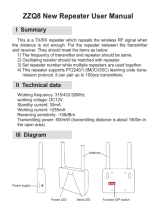
The diagram on the right is an end view of the radio interface
connector on your RI-300. Use the supplied DB-15S female
connector for making all connections to the controller.
PROPER TECHNIQUES FOR QUALITY REPEATER AUDIO
Obtaining good audio in any repeater is based on understanding the design of the equipment. The audio in all frequency
modulation (FM) transmitters or phase modulation (PM) transmitters has what is known as audio pre-emphasis. Pre-emphasis
means that with increasing audio frequency the amount of the modulation will increase. The reverse is performed in all FM
receivers and is called de-emphasis. The RI-300 was designed to operate with flat audio response from the repeater receiver
and transmitter. This means that neither de-emphasis nor pre-emphasis of the audio is performed on the repeat audio path. This
leaves all of the emphasis filtering in the user's radio. The RI-300 controller does include a low pass filter that rolls off the very
high audio frequency content to prevent adjacent channel splatter. The ideal interface between the RI-300 and a FM modulator
is one in which a varactor diode is directly driven. However, the RI-300 does have a de-emphasis filter that can be turned on
for those applications where you may need to interface to a modulator with pre-emphasis. It is not advisable to drive the
microphone input on the transmitters. Most transmitters have significant audio shaping, compensating for the microphone
response and other characteristics. The input connections to the RI-300 must be connected directly to the receiver’s
discriminator for the squelch to work properly. On some receivers, this connection can be made to the squelch circuit input.

Pacific Research Solutions RI-300e User Manual
Page 12
Besides audio frequency response, you should consider the audio amplitude levels to and from the controller. If the levels to
and from the repeater are small, it may be valuable to use shielded cable. We recommend shielded cables at all times. Use
large signal levels whenever possible. On the other hand, do not let the audio signal get large enough where clipping occurs in
any stage of the controller, the receiver, or the transmitter. The RI-300 repeater controller has a built in audio level meter for
setting the RX input level. See section 7 for more details on adjusting the audio levels in the controller. Consider and practice
the above and you will have repeater audio that you and your repeater users will be proud of.
POWER SUPPLY CONNECTIONS (Pins 1 and 9)
The RI-300 operates on 12 volts DC nominal. The DC source voltage must be between 10 and 15 VDC. The controller
typically draws 140 ma. without the status LEDs turned on. Connect the +12v to J1 pin 1. Connect J1 pin 9 to ground or the 12
V return side of the power supply. The repeater builder may elect to incorporate an on/off power switch on the +DC side.
Most repeater owners switch the AC primary side of the power supply.
The RI-300 repeater controller connection to the
power supply
must be over-current protected
. Use of a one-ampere fuse should be the largest capacity considered in your
installation. A ½ amp fuse is best. When connected properly, the green LED on the status LED display will light when the
power is applied and the system enable command is on.
REPEATER RECEIVER AUDIO CONNECTION (Pin 2)
Since the RI-300 controller has the squelch (COR/COS) circuit incorporated on board, the audio input
MUST BE
connected
directly to the receiver discriminator output. Connect the receiver discriminator audio to the RI-300 J1 pin 2 and the receiver
ground or audio return to J1 pin 10.
Do
not connect to the speaker leads
. If you are not familiar with the repeater receiver,
get assistance from someone knowledgeable on the subject or contact our factory for support. If your discriminator does not
have adequate filtering for 455 kHz, you will have to provide for this filtering between the radio and controller. A 10mH
inductor in line with a 1000pF capacitor to ground should work. You may need to adjust these values according to the output
impedance of your discriminator. For best performance all audio connections should be made with a shielded cable. The
controller’s audio path has a flat frequency response from 30 Hz through 4500 Hz except for the CTCSS high pass filter that
cuts off at 300 Hz. When interfaced properly to the repeater receiver and transmitter, the controller will provide superb audio
characteristics.
REPEATER TRANSMITTER AUDIO CONNECTIONS (Pin 3)
Use a direct FM type modulator whenever possible. The RI-300 does have a de-emphasis filter that can be turned on for those
applications in which you need to interface to a modulator with pre-emphasis. It is not advisable to drive the microphone input
on the transmitters. Most microphone inputs have significant audio shaping, compensating for the microphone response and
other characteristics. Always use a shielded cable. Connect the controller transmit audio output J1 pin 3 to the input of the
modulator. Connect the modulator ground or audio return to J1 pin 10. If a FM modulator without pre-emphasis is not
available, the RI-300 can be jumped to drive a phase modulator or modulator with pre-emphasis. Do this by installing jumpers
on JP5 pins 1-2 and JP1 pins 1-2. For FM modulation, install a jumper on JP5 pins 2-3 and no jumper on JP1. See section 17
for more information on this subject.
REPEATER TRANSMITTER PTT OR TRANSMIT KEYING CONNECTION (Pin 4)
The RI-300 repeater controller keys the transmitter at the required times.
WARNING
- As with all repeater controllers, this
controller will key the transmitter at times you may not think of, such as when the ID is due. It never fails when you disconnect
the antenna to connect an in-line wattmeter, the ID goes off or a repeater user arrives on the receiver input. Therefore,
disconnect power to the repeater and controller before performing these operations. The controller PTT keying transistor sinks
current, that is, the transistor pulls to ground the relay or keying stage in the repeater transmitter. This is by far the most
common interface. Should you need to source a voltage to PTT then contact Pacific Research Solutions for application notes.
The keying transistor can sink or pull down (active low) a maximum of 120 ma of current. Connect J1 pin 4 to the repeater
transmitter PTT.
DCS MODULATION (Pin 11)
Some transmitters will not accept DCS modulation with the voice audio. In these applications, the RI-300 will output the DCS
modulation on this pin so that it can be directly connected to the DCS input on your transmitter. Please review section 7 for
additional information on this subject.
/