Page is loading ...

READ AND SAVE THESE INSTRUCTIONS
ZRT-PDIL / ZRT-PDIL-HP
AIRFLOW & ZONE CONTROL
PARALLEL DAMPER IN-LINE ZONE TERMINAL
IOM
*U.S. Pat. No. 9,759,442
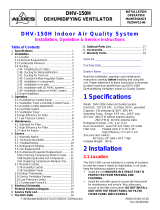
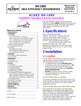
FIGURE 1 - MOUNTING
Integral
Continuous CAR
Flanges for attaching to
rectangular duct in a slip-type
duct connection
Power Connection
(24 VAC or 120 VAC)
to Motorized Damper
Motorized Damper
and Boost CAR
Screw-On Access Plate
Hanging Brackets
AIRFLOW
Description
Aldes Parallel Damper In-Line Zone Terminals
(ZRT-PDIL) are designed to introduce exibility
and dynamic control to central supply or exhaust
ventilation systems. Used in both large and small
systems, the ZRT-PDIL regulates ventilation without
the need for individual fans or traditional VAV
terminal units.
Each ZRT-PDIL is a two-position, pressure-
independent terminal with a control damper to
regulate high limit on-demand airow control and
integral passive regulators for automatic air balancing
of the continuous and boost airow setpoints.
This unique combination provides exible control
schemes without the need for expensive pneumatic,
electronic, or DDC control systems.
The ZRT-PDIL is primarily used for combination low-
ow indoor air quality ventilation or make-up air, and
on demand high-ow spot ventilation using the same
central exhaust or supply fan system. This is achieved
by integrating a minimum Constant Airow Regulator
(CAR) in the terminal end panel and in-line with the
branch duct. The maximum airow is controlled by
a series of 24 VAC or 120 VAC powered motorized
damper(s) and a secondary CAR airow controller.
With the maximum-air motorized control damper
completely closed, the continuous CAR allows steady,
low-volume airow control. (Continuous and Boost
Constant Airow Regulators may be CAR-II or CAR3
depending on required airow. See ZRT-PDIL CFM
Range for details).
When other ZRT-PDIL are activated for on-demand
control of high ow, the unpowered ZRT-PDIL will
maintain the specied continuous rate through the
pressure-independent CAR. Opening the ZRT-PDIL’s
control damper adds its calibrated boost airow rate
to the continuous setpoint.
Mounting
The ZRT-PDIL/ZRT-PDIL-HP is intended to be installed
in-line in a duct system. It is provided with four (4)
mounting tabs that are suitable to suspend the unit
with threaded rods (not included). See Figure 1. The
unit should be installed in a location that provides
clearance for the access plate.
Maintenance
All components of the ZRT-PDIL/ZRT-PDIL-HP are
accessible through the opening provided by the
access plate.
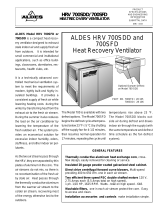
Wiring
ZRT-PDIL/ZRT-PDIL-HP wiring needs to meet all applicable electrical
and building codes. If the electrical connection to the damper
motor wiring box is not accessible after mounting, there needs to
be enough slack (approximately 24”) in the electrical wiring leading
to the wiring box to allow the damper assembly to be removed
through the access opening. This will allow access to the electrical
connections from the access opening.
ZRT-PDIL/ZRT-PDIL-HP models are available with 24 VAC or 120 VAC
motorized dampers. 120 VAC wiring is shown in Figure 2 and 24 VAC
wiring is shown in Figure 3 (next page).

Page 2 | ZRT-PDIL / ZRT-PDIL-HP IOM
Warning
TO REDUCE THE RISK OF FIRE, ELECTRIC SHOCK, OR INJURY
TO PERSONS, OBSERVE THE FOLLOWING:
1. Use this unit only in the manner intended by the manufacturer.
If you have any questions, contact the manufacturer.
2. Before servicing or cleaning the unit, switch power o at service
panel and lock service panel to prevent power from being
switched on accidentally. When the service disconnecting
means cannot be locked, securely fasten a prominent warning
device, such as a tag, to the service panel.
3. Sucient air is needed for proper combustion and exhausting
of gases through the flue (chimney) of fuel-burning
equipment to prevent backdrafting. Follow the heating
equipment manufacturer’s guidelines and safety standards,
such as those published by the National Fire Protection
Association (NFPA), and the American Society of Heating,
Refrigerating and Air-Conditioning Engineers (ASHRAE), and
the local code authorities.
4. In addition to the following manufacturer’s instructions, it is
necessary to comply with federal, state, and local government
codes. Your purchase of this ALDES ventilation system
represents an investment in the health and comfort of the
occupants, as well as an investment in the protection of
the building from the damaging eects of excessive indoor
humidity.
5. Installation work and electrical wiring must be done by
qualied person(s) in accordance with all applicable codes
and standards, including re-rated construction.
6. When cutting or drilling into wall or ceiling, do not damage
electrical wiring and hidden utilities.
Caution
1. For general ventilating use only. Do not use to exhaust
hazardous or explosive materials and vapors.
2. Automatically operated device. To reduce the risk of injury,
disconnect from power supply before servicing.
System Design
Satisfactory performance of a central ventilation system requires:
• Proper integration of all the components, compatible grilles,
and wall/roof caps;
• Proper duct design for friction losses;
• Consideration of acoustic and vibration properties of the fan
and its mounting;
• Acoustic properties of the grilles;
• Consideration of the mode of operation, whether continuous
or automatically controlled by dehumidistat, timer, or
occupancy sensor;
• Installation in a heated or unheated space, with consideration
for the potential of condensation in the ducting or fan housing.
Inspect the carton upon receipt to ensure the terminal has not
been damaged in transit. If damaged, it is the responsibility of
the recipient to le a damage claim with the carrier. ALDES is not
responsible for damage incurred during shipment.
Note: Prior to installation, inspect the terminal to ensure that
damper(s) move freely and that the constant airow regulators
have not shifted during handling. Handle the unit with care to
prevent damage to the housing and other components. Store the
unit indoors if possible. If outdoor storage is required, protection
against moisture and dirt is necessary.
©2020 American ALDES Ventilation Corporation and ©2020 ALDES Canada. ZRT-PDIL / ZRT-PDIL-HP_IOM_0720. Aldes reserves the right to modify its products at any time to introduce new technologies.
For more information, contact your Aldes sales advisor, visit aldes-na.com, call 1.800.255.7749, or find us on
AMERICAN ALDES
ZRT-PDIL
120 VAC WIRING
GNL
BLACK
BLACK or
WHITE
120 VAC
INPUT
AMERICAN ALDES
ZRT-PDIL
24 VAC WIRING
BLACK
BLACK
24 VAC
INPUT
FIGURE 2 FIGURE 3

www.aldes-na.com
CAR3
Constant Airflow Regulator
Installation Operation Maintenance
EN

2
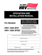
1. AIRFLOW SETTING
Airow rate can be set or adjusted by rotating the dial from either side. The airow indicator will move
to show the selected CFM. The airow label has multiple dened setpoints, but the unique adjustment
mechanism of the CAR3 allows for innite adjustability between the minimum and maximum limits.
Performance charts found in the specications sheet reect this data, with the available range (shaded)
and marked setpoints (lines). The CAR3 will maintain the airow accurately to within +/- 10% of the
indicated lines below for each marked setpoint. At the higher airow rates, the minimum pressure
required to achieve the selected airow may exceed 0.12 in. w.g.
Each diameter has a unique range for both low- and high-pressure variants. The CAR3-L (low-pressure)
is designed for systems with pressures between 0.12 and 1.2 in. w.g. (30 to 300 Pa), and CAR3-H (high-
pressure) between 0.4 and 2.8 in. w.g. (100 to 700 Pa). Factory calibration of the CAR3 is available on
request. Blue color dial = Low-Pressure / Green color dial = High-Pressure.
ADJUSTMENT DIAL
AIRFLOW INDICATOR
2. DIMENSIONS
Ø B A
Size A Ø B
Low-Pressure (Blue)
0.12-1.2 in. w.g
(30-300 Pa)
High-Pressure (Green)
0.4-2.8 in. w.g
(100-700 Pa)
Airflow P/N Airflow P/N
4'' (100 mm) 3’’ 4.3’’ 15-85 CAR3L4R4 30-160 CAR3H4R4
5'' (125 mm) 3.8’’ 5.2’’ 35-180 CAR3L5R5 55-260 CAR3H5R5
6'' (150 mm) 4.6’ 6.0’’ 45-260 CAR3L6R6 60-370 CAR3H6R6

3
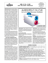
3. INSTALLATION
Rigid Duct
or Register
Box
CAR3
Duct Collar
D
L ≥ 1.2 D
Flex Duct
Flex Duct
CAR3
Duct Collar
or Grille
D
L ≥ 1.2 D
Duct Collar
The CAR3 should be installed in accordance with all applicable building and mechanical codes. If
installed in a metal duct or duct collar with a exible duct connector (listed to UL 2043), the CAR3 must
be inserted at least 1.2 times the duct diameter from the exible duct and/or duct connector.
Orient the CAR3 according to the airow direction
indicated on the device. Horizontal or vertical mounting
is acceptable.
3
6
0
°
Regulator must be installed in a metallic air duct as pictured above. D represents the regulators
maximum outer diameter.
Minimum
1.2 x D
Minimum
1.2 x D
D

www.aldes-na.com
CAR3 IOM_USA. 0620
©2020 American ALDES Ventilation Corporation and ©2020 ALDES Canada. Reproduction or distribution, in whole or in part, of
this document, in any form or by any means, without the express written consent of American ALDES Ventilation Corporation, is
strictly prohibited. The information contained within this document is subject to change without prior written notice.
Aldes North America
USA 800.255.7749 • CAN 800.262.0916 • www.aldes-na.com
5. TROUBLESHOOTING
PROBLEM CAUSE SOLUTION
AIRFLOW TOO LOW
Insufficient duct pressure.
Check fan ratings. Replace fan if too small
Increase fan speed.
Excessive duct air leakage. Seal ducts with mastic or tape.
CAR3 damper
not functioning properly.
Check CFM calibration on CAR3.
Adjust to proper airflow value.
AIRFLOW TOO HIGH
AND/ OR NOISY
OPERATION
CAR3 too close to fan.
Add manual damper to reduce pressure
across CAR3 to normal operating range.
Fan at too high a speed. Lower fan speed.
CAR3 damper
not functioning properly.
Check CFM calibration on CAR3.
Adjust to proper airflow value.
4. MAINTENANCE & WARRANTY
• The CAR3 needs no maintenance when used in normal conditions. The addition of antimicrobial and
anti-static additives in the material increases the longevity and reliability of the CAR3. There is no risk
of dust deposit or obstruction because the CAR3 has no airways subject to clogging. If the intended
application includes air heavily loaded with dust or grease, access to the CAR3 should be possible
through the terminal device or with an access panel or door.
• ALDES Ventilation Corporation warrants the CAR3 to be free from manufacturing defects and
guarantees the performance within specied limits for a period of seven (7) years when installed in
normal environmental air systems for general residential and commercial heating, ventilating and air
conditioning. This warranty does not include installation in industrial
applications or caustic, noxious
or otherwise hazardous airhandling equipment. This warranty
is limited to replacement of the product
only and does not extend to consequential claims.
/