Page is loading ...

NOTES:
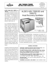
• The hood liner is designed to install inside a custom hood enclosure and operates with a
remotely mounted blower (purchased separately). See Fig. below for hood dimensions.
See chart for ALDES exhaust fans recommended for use with this unit.
• A qualified person must complete the installation of this appliance.
• Plan the installation so that all minimum clearances are met or exceeded.
• IMPORTANT: You must provide support framing and backing in the areas in which you
are securing the liner to in your custom canopy. Failure to do so could damage the liner
and void the warranty.
All dimensional tolerances are 0” to 1/16” unless otherwise stated.
NOTES:
1. The hood liner uses 120 VAC, 60 Hz power. Supply wires should be installed by a
qualified person(s) and must meet all electrical codes. The HLS-30 & HLS-36 Hood
Liner are designed for use with 6” duct. The HLD-36 is designed for use with 8” diameter
round duct and the HLD-42 and HLD-48 Hood Liner are designed for use with 10” diam-
eter duct. Use only rigid metal duct.
2. “Duct Silencers” are available from American ALDES. When planning for installation
using a Duct Silencer, please refer to the installation instructions provided with the unit.
3. A quality cap with built in backdraft damper or an in-line damper is recommended to
minimize cold air return through the duct when the product is not in use.
4. Always install ventilation products with an approved wall or roof cap.
5. Duct performance is improved by using round, smooth metal duct work instead of rectan-
gular.
6. If multiple elbows must be used, ensure that there is a minimum of 24” of straight duct
between any two elbows.
7. Avoid “S” or back to back configurations caused by adjacent elbows.
8. Route ducting to terminate at the hood liner.
WARNINGS: Following Are Manufacturer’s Suggestions. Always Observe Local Building Codes.
1. Liners installed in custom canopies constructed of combustible materials, should be installed with the
combustible material structure a minimum of 36” above the surface of the heating element.
2. Liners installed in custom canopies constructed of noncombustible materials, should be installed with
the noncombustible material structure a minimum of 30” above the surface of the heating element.
3. Follow all instructions regarding minimum safe clearances and installation location. Failure to do so
may result in a safety hazard or fire.
4. To reduce the risk of fire, use only metal ductwork.
READ AND SAVE THESE INSTRUCTIONS
• Before beginning installation, please thoroughly read and become familiar with these instruc-
tions.
• Installation and service must be completed by a qualified installer.
• Failure to properly install this product may void the warranty.
Installer: Please leave these installation instructions with the homeowner.
Owner: Please keep these installation instructions for local electrical inspector’s use for fu-
ture reference.
WARNINGS: TO REDUCE THE RISK OF FIRE, ELECTRIC SHOCK, OR INJURY TO PER-
SONS OBSERVE THE FOLLOWING:
A) Use this unit only in the manner intended by the manufacturer. If you have any ques-
tions, contact the manufacturer.
B) Before servicing or cleaning unit, switch power off at service panel and lock the service
disconnecting means to prevent power form being switched on accidentally. When the
service disconnecting means cannot be locked, securely fasten a prominent warning
device, such as a tag to the service panel.
C) Installation work and electrical wiring must be done by qualified person(s) in accordance
with all applicable codes and standards, including fire-rated construction.
D) Sufficient air is needed for proper combustion and exhausting of gasses through the flue
(chimney) or fuel burning equipment to prevent backdrafting. Follow the heating equip-
ment manufacturer’s guideline and safety standards such as those published by the
National Fire Protection Association (NFPA) and the American Society for Heating, Re-
frigeration and Air Conditioning Engineers (ASHRAE) and the local code authorities.
E) When cutting or drilling into wall or ceiling, do not damage electrical wiring and other
hidden utilities.
F) Duct fans must always be vented to the outdoors.
CAUTION: For general ventilating use only. Do not use to exhaust hazardous or explosive mate-
rials and vapors.
WARNINGS: TO REDUCE THE RISK OF A RANGE TOP GREASE FIRE:
A) Never leave surface units unattended at high settings. Boil-overs may cause smoking
and greasy spillovers that may ignite. Heat oils slowly on low or medium settings.
B) Always turn hood ON when cooking at high heat or when cooking flaming foods.
C) Clean ventilating fans frequently. Grease should not be allowed to accumulate on fan or
filter.
D) Use proper pan size. Always use cookware appropriate for the size of the surface ele-
ment.
WARNING: TO REDUCE THE RISK OF INJURY TO PERSONS IN THE EVENT OF A RANGE
TOP GREASE FIRE, OBSERVE THE FOLLOWING:
A) SMOTHER FLAMES with a close-fitting lid, cookie sheet or metal tray, then turn off the
burner. BE CAREFUL TO PREVENT BURNS. If the flames do not go out immediately,
EVACUATE AND CALL THE FIRE DEPARTMENT.
B) NEVER PICK UP A FLAMING PAN! You may be burned.
C) DO NOT USE WATER, including wet dishcloths or towels - a violent steam explosion will
result.
D) Use an extinguisher ONLY if:
1. You know you have a Class ABC extinguisher, and you already know how to
operate it.
2. The fire is small and contained in the area where it started.
3. The fire department is being called.
4. You can fight the fire with your back to an exit.
PART 1 Planning the Installation
CAUTION:
1. To reduce the risk of fire and to properly exhaust air, the liner must be exhausted to the
outside. Never exhaust into a wall, an attic or a concealed area in the building. This can
create a potential hazard.
2. Consult a licensed ventilation contractor or qualified technician for proper installation of
exhaust ducting.
3. Locate the cooking area for minimum cross drafts -- away from doors and windows,
when possible.
4. Ducts must be of adequate size and duct runs should be as short as possible. When
turns are necessary, keep turning radius as large and as smooth as possible.
5. The ducting must be air tight. Use a minimum of 2 sheet metal screws at every duct joint.
Then, seal the duct joints with high quality duct tape.
6. Only use ductwork constructed of materials deemed acceptable by state, municipal and
local codes.
MODEL UPC# DUCT*
A
BCD
HLS-30 71 130 6 18 28-1/2 6 4
HLS-36 71 131 6 18 34-1/2 6 4
HLD-36 71 136 8 22 34-1/2 8 6
HLD-42 71 142 10 22 40-1/2 10 6
HLD-48 71 148 10 22 46-1/2 10 6

CHOOSING THE RIGHT REMOTE MOUNT BLOWER
Below is a chart of the recommended ALDES fans that can be used with the HLS & HLD Series
range hood liners. Some models are for mounting remotely in the attic. Other models are used
when installation requires a roof mount or wall mount fan.
Model Location Mounting Airflow @ 0" Typical Airflow†
A-6
interior inline 257 190
A6HP
interior inline 392 275
XMV-A6HP
exterior wall 381 330
RMV-A6
exterior roof 227 205
HLS 30 & HLS 36
Model Location Mounting Airflow @ 0" Typical Airflow†
A8-HP
interior inline 521 450
AD-8HP
interior inline 836 650
XMV-A8HP
exterior wall 435 370
RMV-A8HP
exterior roof/wall 401 350
HLD 36
Model Location Mounting Airflow @ 0" Typical Airflow†
A-10HP
interior inline 590 525
AD-10HP
interior inline 1266 1020
RMV-A10HP
exterior roof/wall 753 721
RMV-A10HPT
exterior roof/wall 1008 919
HLD 42 & HLD 48
†Typical airflow is an estimate based on a system with 20-feet of duct, two 90 degree elbows,
backdraft damper, roof cap and filter.
*Representative of full-speed operation @.375 s.p. in a typical installation.
NOTE: Due to the large volume of air that these remote blowers move, it is important that a
source of sufficient makeup air is available to avoid backdrafting in the house.
PART 2 Electrical Connection
WARNINGS:
1. Ensure that the power supply is disconnected before proceeding.
2. Verify that the power supply matches the ratings found on the appliance data label before
proceeding.
3. The complete appliance must be properly grounded at all times when electrical power is
applied.
4. Do not ground the appliance with the neutral (white) house supply wire. A separate
ground wire must be utilized.
5. Failure to complete electrical connections properly may result in damaged or nonfunc-
tional systems. Follow instructions carefully to ensure proper installation.
• It is the owner’s responsibility to ensure that a qualified electrician performs the electrical
connection of this appliance. The electrical installation, including minimum supply wire
size, must comply with the National Electric Code ANSI/NFPA 70-1990 (or latest revision)
and local codes and ordinances.
• A copy of this standard may be obtained from National Fire Protection Association, 1
Batterymarch Park Quincy, Massachusetts 02269-9101
INSTRUCTIONS:
1. A 15 to 20 amp electrical service is recommended for proper electrical supply. Before
determining, calculate amp ratings based on the product label found on the liner and the
ventilator. (Always observe local building codes).
2. Always use a dedicated circuit.
3. Line load is calculated by adding the amperage of the halogen lights to the rated amper-
age of the ventilator (either in-line or roof top). If the ventilator is rated in watts rather than
amps, divide the watts by 120 and this will give you the amperage rating.
4. The ALDES liner is supplied with a 5.0 amp variable speed fan control. Make sure the
rated amperage on the ventilator does not exceed 5.0 amps.
5. The ALDES liner has been designed to accommodate several different motor speed
controls, (for example Thermador
TM
model CTR3-Q). Always consult the manufacturer’s
installation instructions when substituting control switches.
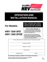
6. Wire connections: (Figure 2)
• Black — 120 VAC from electrical panel (black)
• White — Neutral from electrical panel (white)
• Green — Ground from electrical panel (green)
• Red — 120 VAC variable control to 120 VAC of ventilator
Figure 2
CAUTION: The neutral wire (usually white) for the ventilator must connect to the same neutral
wire that comes from the electrical panel to the liner. It is recommended to run a white
neutral wire from the liner’s white neutral wire along the same path as the red wire from
the liner’s variable speed control to the ventilator.
1259
PART 3 Securing the Liner
SECURING INSTRUCTIONS:
1. Because the professional series liner was designed for custom applications, no mount-
ing holes have been predrilled. This allows you to attach the liner in the areas of the
canopy which have ample support and backing.
2. You must secure the liner through both right and left sides, through the back and through
the top.
3. Remove the filters. Mark and drill screw holes through the liner as required for custom
canopy. Secure the liner by driving screws (provided by others) through the stainless
steel into the framing and backing.
CONNECTING TO THE VENT PIPE:
1. Insert the tabbed end of the galvanized Start Collar into the round hole in the outside top
of the liner.
2. Bend all of the tabs firmly in places against the inside top of the liner. Sheet metal screws
should be placed equidistant through 3 or more tabs. CAUTION: For safety of the
person cleaning this liner, neatly cover the well-flattened tabs with 2 or more layers of
metal tape.
3. Attach the other end of the Start Collar to the range hood vent with a minimum of 3
equidistant screws and metal tape.
PART 4 Use & Care
OPERATING CONTROLS:
1. Always activate the ventilator whenever using cooking appliances.
2. Activate the ventilator a few minutes before starting to cook to establish an airflow pattern within
the room.
3. Adjust the fan speed according to the amount of cooking exhaust.
4. Adjust the dimmable halogen lights as desired.
5. Eliminate air currents in the hood vicinity by shutting nearby windows and doors, turning off
ceiling fans and closing the adjacent heating and air conditioning outlets.
6. Place your largest pans, skillets and stock pots on the rear burners whenever possible.
WARNING: DO NOT operate the vent system without the filters in place, or with dirty, grease
laden filters.
ENERGY SAVING TIPS:
1. Do not operate the blower at a speed that is higher than necessary to remove the cook-
ing exhaust. Running at excessive speeds removes more air from the inside of the
house that must be replaced by outside air. This may be especially costly when your
home’s heating or air conditioning system is in operation. Turn off the unit once the
smoke and cooking odors have been eliminated.
2. Clean filters and grease laden surfaces often to improve efficiency.
3. Always use lids on cookware to retain heat and moisture.
4. Minimize the amount of liquid used to cook food.
5. Select cookware of proper size, material and construction for the cooking task being
performed.
CARE & CLEANING:
1. Proper cleaning is necessary to maintain performance and appearance, while also en-
suring safe operation. The frequency of cleaning should be adjusted according to the
type and amount of cooking. Best results will be achieved by cleaning soiled compo-
nents as soon as possible.
2. Filters must be cleaned regularly. Remove one filter at a time. On models HLD-36, 42,
& 48, grasp the filter handle and gently pull toward you, then down and back. Filter
should be installed with the handle in the rear filter slot. On model HLS-30, insert a blunt
knife into the small slot in the front edge of the filter. Push down and back. Filter should
be installed with small slot at the front of the filter.
3. The filters may be cleaned by hand washing in hot water using a mild detergent solution,
or by placing them in the top rack of an automatic dishwasher. Dry the filters completely
before using again.
4. Stainless steel surfaces should be cleaned with a solution of mild detergent and warm
water. Rinse and dry with a soft lint-free cloth. CAUTION: Do not use any type of pad
that will scratch the liner.
5. CAUTION: If a commercially available stainless steel cleaner is used, it is important to
read the labels for chlorine compounds. Chlorine is a corrosive substance. If these
compounds are present, rinse thoroughly and dry with a soft lint-free cloth. Follow polish
manufacturer’s instructions.
6. Always wipe stainless steel surfaces with the grain. Never wipe across the grain.
7. After cleaning, reinstall the filters carefully.
REPLACING LIGHT BULBS:
Par 20 halogen lamps are available in many different styles and sizes. Following is a list recomended
by the manufacturer:
• Phillips MASTER Line 50 watts 120V • Felt Electric 50 watt 130V
• Industrial Grade Premium Quality
TM
P.Q.L. Incorporated Code 83009
4537 NORTHGATE COURT
SARASOTA, FL 34234-2124, USA
Tel: 941-351-3441 Fax: 941-351-3442
www.americanaldes.com
E-mail: [email protected]
/