Page is loading ...

69-ALD-01
0709
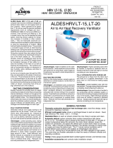
New Auto Dehumidistat Function
prevents unwanted use of the dehumidistat when outdoor temperatures exceed 15°C (59°F).
INSTALLER: Leave this manual for the homeowner
Operation and Installation Manual
Premium Series
Installation and wiring to be in accordance with CEC, NEC
and local electrical codes.
Important: Read and save these instructions.
HRV95SRD
HRV155SRD
HRV200SRD
ERV200S
HRV300DDD
HRV120SRD
LEAVE FOR HOMEOWNER
TO BE COMPLETED BY CONTRACTOR AFTER INSTALLATION
Installing Contractor _________________________________________Telephone / Contact _____________________
Serial Number______________________________________________Installation Date ________________________
Model _________________________________________________________________________________________

2
Warranty........................................................................................2
Technical Data - Model HRV95SRD ...........................................3
Port Configuration and Airflow - Model HRV95SRD .................4
Technical Data - Model HRV120SRD .........................................5
Technical Data - Model HRV155SRD .........................................6
Technical Data - Model HRV200SRD .........................................7
Technical Data - Model HRV300DDD .......................................8
Technical Data - Model ERV200S ...............................................9
Controlling your HRV/ERV
How the Dehumidistat Works
Glossary.......................................................................................10
The Premium Series Digital Control Model ADXC-II...............11
The Premium Series Programmable Control Model APV..........12
Optional Timers
The DH-II Dehumidistat .............................................................13
Installation Methods....................................................................14
Installation Diagrams.............................................................15-17
Installation...................................................................................18
Engineering Data HRV ...............................................................19
Suspending the HRV120SRD.....................................................20
Drain Connection
Grilles .........................................................................................21
Weatherhood Installation ............................................................22
Installation of the Main Control..................................................23
Installation and Operation 20/40/60/ Minute Timers
Installation of Mechanical Timers...............................................24
Installation of ZRT Zone Register Terminal...............................25
Interlocking HRV/ERV to an Airhandler/Furnace Blower
Dry Contacts................................................................................26
Pitot Tube Air Flow Balancing ...................................................27
Air Flow Measuring Kit..............................................................28
Balancing Collar Instructions......................................................29
Maintenance Routine for your HRV/ERV..................................30
Troubleshooting your HRV/ERV System...................................31
Wiring Diagrams....................................................................32-33
Heat and Energy Recovery Ventilator Warranty .......................34
All Heat Recovery Ventilators carry a fifteen (15) year warranty
on the heat recovery core and a 2 (two) year replacement parts
warranty.
All Energy Recovery Ventilators carry a 5 (five) year warranty on
the energy recovery core and a 2 (two) year replacement parts
warranty.
During the warranty period, if any core experiences a failure or
perforation caused by normal use while owned by the original
purchaser, a replacement core (FOB our plant) will be supplied at
no expense.
Table of Contents
Warranty
IMPORTANT -
PLEASE READ THIS MANUAL
BEFORE INSTALLING UNIT.
Due to ongoing research and product development,
specifications, ratings and dimensions are subject to
change without notice.
NOTE
CAUTION
Before installation, careful consideration must be
given to how this system will operate if connected
to any other piece of mechanical equipment, i.e. a
forced air furnace or air handler, operating at a
higher static. After installation, the compatibility of
the two pieces of equipment must be confirmed, by
measuring the air flows of the HRV/ERV, by using
the balancing procedure found in this manual.
NEVER install a ventilator in a situation where its
normal operation, lack of operation or partial
failure may result in the backdrafting or improper
functioning of vented combustion equipment.
Do Not Connect the HRV/ERV supply air duct to the
supply or return duct of an airconditioner, in
climate zones where the outdoor air dew point
often exceeds 55°F (13°C) (that is, in warm, humid
climates). Failure to observe this may result in
condensation of moisture inside the ducting. It is
not recommended to operate the HVAC fan
continuously in such climates.

3
Removable
Heat Recovery
Core
Drain Pan
Drain spout
FRONT TOP
knockout for
side mounting of
EXHAUST return port
6" round collar
converted to oval
minimum
18 inches (459 mm)
required for
service access
Threaded
inserts (4)
at corners
SUPPLY
Fresh air
from outside
5" round collar
SUPPLY
Fresh air
to building
6" round
(conv. to oval)
collar
EXHAUST
Stale Air
to outside
5" round collar
EXHAUST
Return air
from building
Choice of port location
Knockouts on top and
side of unit (use 1 only)
6" round (conv. to oval)
collar supplied
18.5"
(470 mm)
18.5"
(470 mm)
16"
(406 mm)
SIDE
Hanging
straps (4)
24.5"
(622 mm)
Date: ___________________________________________
Tag: _____________________Qty:___________________
Project: _________________________________________
Engineer: _______________________________________
Contractor: ______________________________________
Supplier: ________________________________________
Quote#: _________________________________________
Submitted by: ____________________________________
Model HRV95SRD
ENGINEERING DATA
THERMALLY CONDUCTIVE, PATENTED ALUMINUM CORE
The cross-flow heat recovery core transfers heat between the two airstreams. It is easily removed
for cleaning or service.
MOTORS AND BLOWERS
Each air stream has one centrifugal blower driven by a common PSC motor. 5 speed fan operation.
FILTERS
Washable air filters in exhaust and supply air streams.
MOUNTING THE HRV
Four threaded inserts at corners of the cabinet designed to accept PVC
reinforced polyester straps that are supplied with the unit.
DEFROST
Recirculating defrost system.
CASE
Twenty gauge prepainted galvanized steel (G60) for superior corrosion resistance. Insulated to
prevent exterior condensation. Drain connections 2 - 1/2" (12 mm) OD.
WEIGHT 52 lbs. (23.6 kg) SHIPPING WEIGHT 56 lbs. (25.4 kg)
PREMIUM SERIES ELECTRONICS
• Built-in Relay for Interfacing to furnace
• Built-in Dehumidistat disable feature
CONTROLS & ELECTRONICS
The Premium Series Digital Control (Model ADXC-II) is included with unit and can be wall
mounted in a central location of the home.
• 2 Speed Operation on each mode
• 4 user selectable operational modes: Continuous Ventilation, 20 ON/40 OFF,
20 ON/40 Recirculation, Continuous Recirculation
• Adjustable Dehumidistat function built into the main wall control
• Connected to 3 wire 20 gauge low voltage wire
OPTIONAL PROGRAMMABLE CONTROL
Premium Series Digital Control (Model APVC) - contains all the features of the Premium Series
Digital Control with 5 speeds and 7/24 programmable ventilation, (3 wire) 20 gauge
wire (min.) 100' length
OPTIONAL TIMERS
DET-II 20/40/60 Minute Timer - Initiates high speed ventilation for 20, 40, or 60
minutes, (3 wire) 20 gauge wire (min.) 100' length
28998 Mechanical Timer - Initiates High speed ventilation for up to 60 minutes,
(2 wire) 20 gauge wire (min.) 100' length
OPTIONAL ACCESSORIES
DH-II Dehumidistat - Initiates high speed ventilation when the indoor humidity level is
above the set point. (3 wire) 20 gauge wire (min.) 100' length
22025 Weatherhoods, Two - 5” (125 mm) c/w 1/4” (6 mm) mesh screen
ZRT-1 Zone Register Terminal permits intermittent ventilation control at any exhaust terminal,
controlled by local timer switch, simultaneously turns HRV/ERV on high speed.
Suggested use: bathrooms and shower areas.
ZRT-2 Zone Register Terminal permits constant low airflow with boost exhaust, controlled by
local timer switch, simultaneously turns HRV/ERV on high speed. Suggested use:
bathroom and shower areas.
Constant Exhaust Registers: Airflows remain constant while other zones are turned on and
HRV/ERV runs at high speed. Suggested use: laundry areas and pet rooms.
WARRANTY
Units carry a fifteen (15) year warranty
on the heat recovery core and a two (2)
year replacement parts warranty.
All units conform to
CSA and UL standards.
*Sensible Efficiency – thermal **Latent Efficiency – moisture
Note: Effectiveness - based on temp. differential between the 2 airstreams
Efficiency – takes into account all power inputs
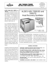
Performance (HVI certified)
Net supply air flow in cfm (L/s) against external static pressure
E.S.P
(external static pressure) [cfm (L/s)]
@ 0.1" (25 Pa) 76 (36)
@ 0.2" (50 Pa) 73 (34)
@ 0.3" (75 Pa) 70 (33)
@ 0.4" (100 Pa) 66 (31)
@ 0.5" (125 Pa) 60 (29)
Max. Temperature Recovery 88%
Sensible Effectiveness
@ 60 cfm (28 L/s) 32°F (0°C) 88%
*Sensible Efficiency
@ 60 cfm (28 L/s) 32°F (0°C) 75%
*Sensible Efficiency
@ 61 cfm (29 L/s) -13°F (-25°C) 68%
VAC @ 60HZ 120
WATTS / Low speed. 59
WATTS / High speed 89
Amp rating 0.9
Static Press ure (in w.g.)
Air Flow (cfm)
Speed 5
Speed 4
Speed 3
Speed 2
Speed 1
20
30
40
50
60
70
0 0.1 0.2 0.3 0.4 0.5 0.6
80
4 - Medium High Speed
3 - Medium Speed
2 - Medium Low Speed
1 - Low Speed
5 - High Speed
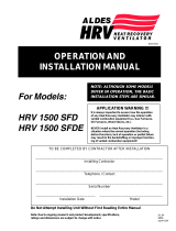
DIMENSIONS HRV95SRD (inches (mm)

Port Configuration and Airflow Model HRV95SRD
HRV95SRD Port Specifications
The Heat Recovery Ventilator (HRV) has been designed to allow
the installer to choose between two possible positions on the
cabinet for the INDOOR EXHAUST (return from building) port.
Illustrations in this manual show standard (side mounted) port
location. The same specifications apply to both HRV95SRD
setups, regardless of which port position is selected.
Variable Port Location / Installation
(Model HRV95SRD only)
The exhaust return port collar is not factory installed. Installer
may choose either side mounted or alternate top mounted port by
simply removing one of the two knock-out plates and attaching a
port collar (supplied). To remove knock-out plate, insert a utility
knife into the knock-out slits and trace them completely to
puncture protective film underneath. Then, cut the solid tabs
between the slits, using tin snips or side cutters, and remove the
knock-out plate. If any protective film still blocks the opening,
remove it now.
In order to make the HRV95SRD as space efficient as possible, the
INDOOR supply and return ports are converted from round to oval
shape. Overall size of the port remains the same. Simply bend a
standard duct fitting to the correct shape, and attach to the oval
port using the same method as for a round port.
HRV95SRD Air Flow
Stale air enters the FRONT RIGHT side port. The air will pass
down the front half of the core, then up the back half of the core
and out the RIGHT REAR port.
Fresh outdoor air will enter the LEFT REAR port and pass down
the back half of the core. It will then pass up the front half of the
core, and out the LEFT FRONT port. This unique configuration
allows the air to actually travel through the core twice, making the
HRV95SRD almost as efficient as a double core unit.
Variable Port Location
SIDE MOUNTED PORT TOP MOUNTED PORT
standard location alternate location
Round port bent to oval
4

ENGINEERING DATA
THERMALLY CONDUCTIVE, PATENTED ALUMINUM CORE
The cross-flow heat recovery core transfers heat between the two airstreams. It is easily removed for
cleaning or service.
MOTORS AND BLOWERS
Each air stream has an independent motorized impeller, 5 speed fan operation.
FILTERS
Washable air filters in exhaust and supply air streams.
MOUNTING THE HRV
Four threaded inserts at corners of case designed to accept four reinforced polyester straps that are
supplied with the unit.
DEFROST
Recirculating damper defrost system.
CASE
Twenty gauge prepainted galvanized steel (G60) for superior corrosion resistance. Insulated to prevent
exterior condensation. Drain connections 2 - 1/2" (12 mm) OD.
WEIGHT 42 lbs. (19 kg) SHIPPING WEIGHT 45 lbs. (20.5 kg)
PREMIUM SERIES ELECTRONICS
• Built-in Relay for Interfacing to furnace
• Built-in Dehumidistat disable feature
CONTROLS & ELECTRONICS
The Premium Series Digital Control (Model ADXC-II) is included with unit and can be wall
mounted in a central location of the home.
• 2 Speed Operation on each mode
• 4 user selectable operational modes: Continuous Ventilation, 20 ON/40 OFF,
20 ON/40 Recirculation, Continuous Recirculation
• Adjustable Dehumidistat function built into the main wall control
• Connected to 3 wire 20 gauge low voltage wire
OPTIONAL PROGRAMMABLE CONTROL
Premium Series Digital Control (Model APVC) - contains all the features of the Premium Series
Digital Control with 5 speeds and 7/24 programmable ventilation, (3 wire) 20 gauge
wire (min.) 100' length
OPTIONAL TIMERS
DET-II 20/40/60 Minute Timer - Initiates high speed ventilation for 20, 40, or 60 minutes,
(3 wire) 20 gauge wire (min.) 100' length
28998 Mechanical Timer - Initiates High speed ventilation for up to 60 minutes,
(2 wire) 20 gauge wire (min.) 100' length
OPTIONAL ACCESSORIES
DH-II Dehumidistat - Initiates high speed ventilation when the indoor humidity level is
above the set point. (3 wire) 20 gauge wire (min.) 100' length
22025 Weatherhoods, Two - 5” (125 mm) c/w 1/4” (6 mm) mesh screen
ZRT-1 Zone Register Terminal permits intermittent ventilation control at any exhaust terminal,
controlled by local timer switch, simultaneously turns HRV/ERV on high speed.
Suggested use: bathrooms and shower areas.
ZRT-2 Zone Register Terminal permits constant low airflow with boost exhaust, controlled by
local timer switch, simultaneously turns HRV/ERV on high speed. Suggested use:
bathroom and shower areas.
Constant Exhaust Registers: Airflows remain constant while other zones are turned on and
HRV/ERV runs at high speed. Suggested use: laundry areas and pet rooms.
Model HRV120SRD
All units conform to CSA and UL standards.
Date: ___________________________________________
Tag: _____________________Qty:___________________
Project: _________________________________________
Engineer: _______________________________________
Contractor: ______________________________________
Supplier: ________________________________________
Quote#: _________________________________________
Submitted by: ____________________________________
*Sensible Efficiency – thermal **Latent Efficiency – moisture
Note: Effectiveness - based on temp. differential between the 2 airstreams
Efficiency – takes into account all power inputs
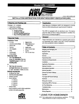
Performance (HVI certified)
Net supply air flow in cfm (L/s) against external static pressure
E.S.P
(external static pressure) [cfm (L/s)]
@ 0.1" (25 Pa) 150 (71)
@ 0.2" (50 Pa) 146 (69)
@ 0.3" (75 Pa) 134 (63)
@ 0.4" (100 Pa) 121 (57)
@ 0.5" (125 Pa) 106 (50)
@ 0.6" (150 Pa) 92 (43)
Max. Temperature Recovery 78%
Sensible Effectiveness
@ 65 cfm (31 L/s) 32°F (0°C) 76%
*Sensible Efficiency
@ 65 cfm (31 L/s) 32°F (0°C) 64%
*Sensible Efficiency
@ 68 cfm (32 L/s) -13°F (-25°C) 66%
VAC @ 60HZ 120
WATTS / Low speed. 84
WATTS / High speed 117
Amp rating 1.4
3
2
1
20
40
60
80
100
120
140
0 0,1 0,2 0,3 0,4 0,5 0,6 0,7 0,8 0,9
3 - High Speed
2 - Medium Speed
1 - Low Speed
Air Flow (cfm)
Static Pressure (In w.g.)
FRESH AIR
FROM OUTSIDE
STALE AIR
FROM
BUILDING
FRESH AIR
TO
BUILDING
FRONT VIEW (IF MOUNTING VERTICALLY)
BOTTOM VIEW (IF MOUNTING HORIZONTALLY)
STALE AIR
TO OUTSIDE
25 1/8”
(637 mm)
22”
(559 mm)
9 1/8”
(232 mm)
WARRANTY
Units carry a fifteen (15) year warranty
on the heat recovery core and a two
(2) year replacement parts warranty.
DIMENSIONS HRV120SRD
(inches (mm)
5

ENGINEERING DATA
THERMALLY CONDUCTIVE, PATENTED ALUMINUM CORE
The cross-flow heat recovery core transfers heat between the two airstreams. It is easily removed for
cleaning or service.
MOTORS AND BLOWERS
Each air stream has one centrifugal blower driven by a common PSC motor. 5 speed fan operation.
FILTERS
Washable air filters in exhaust and supply air streams.
MOUNTING THE HRV
Four threaded inserts at corners of case designed to accept four reinforced polyester straps that are
supplied with the unit.
DEFROST
Recirculating damper defrost system.
CASE
Twenty gauge prepainted galvanized steel (G60) for superior corrosion resistance. Insulated to prevent
exterior condensation. Drain connections 2 - 1/2" (12 mm) OD.
WEIGHT 71lbs (32.5Kg) SHIPPING WEIGHT 73lbs (33.5Kg)
PREMIUM SERIES ELECTRONICS
• Built-in Relay for Interfacing to furnace
• Built-in Dehumidistat disable feature
CONTROLS & ELECTRONICS
The Premium Series Digital Control (Model ADXC-11) is included with unit and can be wall mounted
in a central location of the home.
• 2 Speed Operation on each mode
• 4 user selectable operational modes: Continuous Ventilation, 20 ON/40 OFF,
20 ON/40 Recirculation, Continuous Recirculation
• Adjustable Dehumidistat function built into the main wall control
• Connected to 3 wire 20 gauge low voltage wire
OPTIONAL PROGRAMMABLE CONTROL
Premium Series Digital Control (Model APVC-II) - contains all the features of the Premium Series
Digital Control with 5 speeds and 7/24 programmable ventilation, (3 wire) 20 gauge wire
(min.) 100' length
OPTIONAL TIMERS
DET-II 20/40/60 Minute Timer - Initiates high speed ventilation for 20, 40, or 60 minutes,
(3 wire) 20 gauge wire (min.) 100' length
28998 Mechanical Timer - Initiates High speed ventilation for up to 60 minutes,
(2 wire) 20 gauge wire (min.) 100' length
OPTIONAL ACCESSORIES
DH-II Dehumidistat - Initiates high speed ventilation when the indoor humidity level is above
the set point. (3 wire) 20 gauge wire (min.) 100' length
22026 Weatherhoods, Two - 6” (150 mm) c/w 1/4” (6 mm) mesh screen
ZRT-1 Zone Register Terminal permits intermittent ventilation control at any exhaust terminal,
controlled by local timer switch, simultaneously turns HRV/ERV on high speed. Suggested
use: bathrooms and shower areas.
ZRT-2 Zone Register Terminal permits constant low airflow with boost exhaust, controlled by local
timer switch, simultaneously turns HRV/ERV on high speed. Suggested use: bathroom and
shower areas.
Constant Exhaust Registers: Airflows remain constant while other zones are turned on and HRV/ERV
runs at high speed. Suggested use: laundry areas and pet rooms.
Model HRV155SRD
Date: ___________________________________________
Tag: _____________________Qty:___________________
Project: _________________________________________
Engineer: _______________________________________
Contractor: ______________________________________
Supplier: ________________________________________
Quote#: _________________________________________
Submitted by: ____________________________________
*Sensible Efficiency – thermal **Latent Efficiency – moisture
Note: Effectiveness - based on temp. differential between the 2 airstreams
Efficiency – takes into account all power inputs
Performance (HVI certified)
Net supply air flow in cfm (L/s) against external static pressure
E.S.P
(external static pressure) [cfm (L/s)]
@ 0.1" (25 Pa) 150 (71)
@ 0.2" (50 Pa) 146 (69)
@ 0.3" (75 Pa) 134 (63)
@ 0.4" (100 Pa) 121 (57)
@ 0.5" (125 Pa) 106 (50)
@ 0.6" (150 Pa) 92 (43)
Max. Temperature Recovery 78%
Sensible Effectiveness
@ 65 cfm (31 L/s) 32°F (0°C) 76%
*Sensible Efficiency
@ 65 cfm (31 L/s) 32°F (0°C) 64%
*Sensible Efficiency
@ 68 cfm (32 L/s) -13°F (-25°C) 66%
VAC @ 60HZ 120
WATTS / Low speed. 49
WATTS / High speed 120
Amp rating 1.4
5
4
3
2
1
20
40
60
80
100
120
140
160
0 0.1 0.2 0.3 0.4 0.5 0.6 0.7
Static Pressure (in w .g.)
Air Flow (cfm)
5 - High Speed
4 - Medium High Speed
3 - Medium Speed
2 - Medium Low Speed
1 - Low speed
WARRANTY
Units carry a fifteen (15) year
warranty on the heat recovery
core and a two (2) year
replacement parts warranty.
6
BALANCING DAMPER
33 5/8"
(850 mm)
STALE AIR
FROM INSIDE
FRESH AIR
FROM OUTSIDE
STALE AIR
TO OUTSIDE
FRESH AIR
TO INSIDE
14 3/4"
(375 mm)
19"
(483 mm)
*All Duct Connections 6" (150 mm)
CONDENSATE DRAINS
FILTERS
BLOWERS
*NOTE: Fro nt
cle arance
of 25 inches
(63 5 mm)
is recommended
for ser vicing unit.
RECIRCULATING
DEFROST
DAMPER
MOTOR
CORE
BALANCING DAMPER
All units conform to CSA and UL standards.
DIMENSIONS
HRV155SRD
inches (mm)

DIMENSIONS
HRV200SRD
inches (mm)
7
Model HRV200SRD
All units conform to CSA and UL standards.
ENGINEERING DATA
THERMALLY CONDUCTIVE, PATENTED ALUMINUM CORE
The cross-flow heat recovery core transfers heat between the two airstreams. It is easily removed
for cleaning or service.
MOTORS AND BLOWERS
Each air stream has one centrifugal blower driven by a common PSC motor. 5 speed fan operation.
FILTERS
Washable air filters in exhaust and supply air streams.
MOUNTING THE HRV
Four threaded inserts at corners of case designed to accept four reinforced polyester straps supplied
with the unit.
DEFROST
Recirculating damper defrost system.
CASE
Twenty gauge prepainted galvanized steel (G60) for superior corrosion resistance. Insulated to
prevent exterior condensation. Drain connections 2 - 1/2" (12 mm) OD.
WEIGHT 75 lbs (34 Kg) SHIPPING WEIGHT 77 lbs (38 Kg)
PREMIUM SERIES ELECTRONICS
• Built-in Relay for Interfacing to furnace
• Built-in Dehumidistat disable feature
CONTROLS & ELECTRONICS
The Premium Series Digital Control (Model ADXC-11) is included with unit and can be wall
mounted in a central location of the home.
• 2 Speed Operation on each mode
• 4 user selectable operational modes: Continuous Ventilation, 20 ON/40 OFF,
20 ON/40 Recirculation, Continuous Recirculation
• Adjustable Dehumidistat function built into the main wall control
• Connected to 3 wire 20 gauge low voltage wire
OPTIONAL PROGRAMMABLE CONTROL
Premium Series Digital Control (Model APVC) - contains all the features of the Premium Series
Digital Control with 5 speeds 7/24 programmable ventilation, (3 wire) 20 gauge wire
(min.) 100' length
OPTIONAL TIMERS
DET-II 20/40/60 Minute Timer - Initiates high speed ventilation for 20, 40, or 60 minutes,
(3 wire) 20 gauge wire (min.) 100' length
28998 Mechanical Timer - Initiates High speed ventilation for up to 60 minutes,
(2 wire) 20 gauge wire (min.) 100' length
OPTIONAL ACCESSORIES
DH-II Dehumidistat - Initiates high speed ventilation when the indoor humidity level is
above the set point. (3 wire) 20 gauge wire (min.) 100' length
22026 Weatherhoods, Two - 6” (150 mm) c/w 1/4” (6 mm) mesh screen
ZRT-1 Zone Register Terminal permits intermittent ventilation control at any exhaust terminal,
controlled by local timer switch, simultaneously turns HRV/ERV on high speed.
Suggested use: bathrooms and shower areas.
ZRT-2 Zone Register Terminal permits constant low airflow with boost exhaust, controlled by
local timer switch, simultaneously turns HRV/ERV on high speed. Suggested use:
bathroom and shower areas.
Constant Exhaust Registers: Airflows remain constant while other zones are turned on and HRV/ERV
runs at high speed. Suggested use: laundry areas and pet rooms.
Date: ___________________________________________
Tag: _____________________Qty:___________________
Project: _________________________________________
Engineer: _______________________________________
Contractor: ______________________________________
Supplier: ________________________________________
Quote#: _________________________________________
Submitted by: ____________________________________
*Sensible Efficiency – thermal **Latent Efficiency – moisture
Note: Effectiveness - based on temp. differential between the 2 airstreams
Efficiency – takes into account all power inputs
Performance (HVI certified)
Net supply air flow in cfm (L/s) against external static pressure
E.S.P
(external static pressure) [cfm (L/s)]
@ 0.1" (25 Pa) 207 (97)
@ 0.2" (50 Pa) 200 (94)
@ 0.3" (75 Pa) 184 (87)
@ 0.4" (100 Pa) 171 (80)
@ 0.5" (125 Pa) 152 (71)
@ 0.6" (150 Pa) 130 (61)
@ 0.7" (175 Pa) 116 (55)
@ 0.8" (200 Pa) 86 (40)
Max. Temperature Recovery 74%
Sensible Effectiveness
@ 66 cfm (31 L/s) 32°F (0°C) 74%
*Sensible Efficiency
@ 66 cfm (31 L/s) 32°F (0°C) 64%
Sensible Efficiency
@109 cfm (51 L/s) -13°F (-25°C) 62%
VAC @ 60HZ 120
WATTS / Low speed. 87
WATTS / High speed 164
Amp rating 1.4
1
2
3
4
5
40
60
80
100
120
140
160
180
200
220
0 0.1 0.2 0.3 0.4 0.5 0.6 0.7 0.8 0.9
Static Pressure (in w.g.)
Air Flow (cfm)
5 - High Speed
*4 - Medium High Speed
*3 - Medium Speed
*2 - Medium Low Speed
*1 - Low speed
* Manufacturers Data
WARRANTY
Units carry a fifteen (15) year
warranty on the heat recovery core
and a two (2) year replacement parts
warranty.
BALANCING DAMPER
33 5/8"
(850 mm)
STALE AIR
FROM INSIDE
FRESH AIR
FROM OUTSIDE
STALE AIR
TO OUTSIDE
FRESH AIR
TO INSIDE
14 3/4"
(375 mm)
19"
(483 mm)
*All Duct Connections 6" (150 mm)
CONDENSATE DRAINS
FILTERS
BLOWERS
*NOTE: Fr ont
clearan ce
of 25 inches
(635 m m)
is rec ommen ded
for servici ng unit.
RECIRCULATING
DEFROST
DAMPER
MOTOR
CORE
BALANCING DAMPER
All Duct
Connections
6” (160 mm)

8
49"
(1245)
STALE AIR
TO OUTSIDE
FRESH AIR
TO INSIDE
14 3/4"
(375)
19"
(483)
Ports
7" (178 mm)
CONDENSATE
DRAINS
BLOWERS
*NOTE: Front clearance of 25 inches (635 mm)
is recommended for servicing unit.
MOTOR
FRESH AIR
FROM OUTSIDE
STALE AIR
FROM INSIDE
FILTER
DEFROST
DAMPER
DEFROST AIR
FROM INSIDE
FILTER
Ports
6" (150 mm)
METAL CLASPS
ENGINEERING DATA
THERMALLY CONDUCTIVE, PATENTED ALUMINUM CORE
The cross-flow heat recovery core transfers heat between the two airstreams. The two cores are
arranged for highly efficient counter current airflow.
MOTORS AND BLOWERS
Each air stream has one centrifugal blower driven by a common PSC motor. 5 speed fan operation.
FILTERS
Washable air filters in exhaust and supply air streams.
MOUNTING THE HRV
Four threaded inserts at corners of case designed to accept four reinforced polyester straps that are
supplied with the unit.
DEFROST
Damper defrost system.
CASE
Twenty gauge prepainted galvanized steel (G60) for superior corrosion resistance. Insulated to
prevent exterior condensation. Drain connections 2 - 1/2" (12 mm) OD.
WEIGHT 106 lbs (48 Kg) SHIPPING WEIGHT 108 lbs (49 Kg)
PREMIUM SERIES ELECTRONICS
• Built-in Relay for Interfacing to furnace
• Built-in Dehumidistat disable feature
CONTROLS & ELECTRONICS
The Premium Series Digital Control (Model ADXC-II) is included with unit and can be wall
mounted in a central location of the home.
• 2 Speed Operation on each mode
• 2 user selectable operational modes: Continuous Ventilation and 20 ON/40 OFF
• Adjustable Dehumidistat function built into the main wall control
• Connected to 3 wire 20 gauge low voltage wire
OPTIONAL PROGRAMMABLE CONTROL
Premium Series Digital Control (Model APVC) - contains all the features of the Premium Series
Digital Control with 5 speeds and 7/24 programmable ventilation, (3 wire) 20 gauge
wire (min.) 100' length
OPTIONAL TIMERS
DET-II 20/40/60 Minute Timer - Initiates high speed ventilation for 20, 40, or 60
minutes, (3 wire) 20 gauge wire (min.) 100' length
28998 Mechanical Timer - Initiates High speed ventilation for up to 60 minutes,
(2 wire) 20 gauge wire (min.) 100' length
OPTIONAL ACCESSORIES
DH-II Dehumidistat - Initiates high speed ventilation when the indoor humidity level is
above the set point. (3 wire) 20 gauge wire (min.) 100' length
22026 Weatherhoods, Two - 6” (150 mm) c/w 1/4” (6 mm) mesh screen
ZRT-1 Zone Register Terminal permits intermittent ventilation control at any exhaust terminal,
controlled by local timer switch, simultaneously turns HRV/ERV on high speed.
Suggested use: bathrooms.
ZRT-2 Zone Register Terminal permits constant low airflow with boost exhaust, controlled by
local timer switch, simultaneously turns HRV/ERV on high speed. Suggested use:
bathroom and shower areas.
Constant Exhaust Registers: Airflows remain constant while other zones are turned on and
HRV/ERV runs at high speed. Suggested use: laundry areas and pet rooms.
Model HRV300DDD
DIMENSIONS
HRV300DDD
inches (mm)
Date: ___________________________________________
Tag: _____________________Qty:___________________
Project: _________________________________________
Engineer: _______________________________________
Contractor: ______________________________________
Supplier: ________________________________________
Quote#: _________________________________________
Submitted by: ____________________________________
All units conform to
CSA and UL standards.
*Sensible Efficiency – thermal **Latent Efficiency – moisture
Note: Effectiveness - based on temp. differential between the 2 airstreams
Efficiency – takes into account all power inputs
Performance (HVI certified)
Net supply air flow in cfm (L/s) against external static pressure
E.S.P
(external static pressure) [cfm (L/s)]
@ 0.1" (25 Pa) 265 (125)
@ 0.2" (50 Pa) 260 (123)
@ 0.3" (75 Pa) 250 (118)
@ 0.4" (100 Pa) 235 (111)
@ 0.5" (125 Pa) 220 (104)
@ 0.6" (150 Pa) 203 (96)
@ 0.7" (175 Pa) 186 (88)
@ 0.8" (200 Pa) 167 (79)
Max. Temperature Recovery 90%
Sensible Effectiveness
@ 119 cfm (56 L/s) 32°F (0°C) 90%
*Sensible Efficiency
@ 119 cfm (56 L/s) 32°F (0°C) 79%
*Sensible Efficiency
@ 125 cfm (59 L/s) -13°F (-25°C) 75%
VAC @ 60HZ 120
WATTS / Low speed. 150
WATTS / High speed 333
Amp rating 2.9
1
2
3
4
5
60
80
100
120
140
160
180
200
220
240
260
280
0 0.1 0.2 0.3 0.4 0.5 0.6 0.7 0.8 0.9
Static Pressure (in w.g.)
Air Flow (cfm)
5 - High Speed
*4 - Medium High Speed
*3 - Medium Speed
*2 - Medium Low Speed
*1 - Low speed
* Manufacturers Data
WARRANTY
Units carry a fifteen (15) year
warranty on the heat recovery
core and a two (2) year
replacement parts warranty.

9
Model ERV200S
Date: ___________________________________________
Tag: _____________________Qty:___________________
Project: _________________________________________
Engineer: _______________________________________
Contractor: ______________________________________
Supplier: ________________________________________
Quote#: _________________________________________
Submitted by: ____________________________________
All units conform to
CSA and UL standards.
20
40
60
80
100
120
140
160
180
200
220
0 0.1 0.2 0.3 0.4 0.5 0.6 0.7 0.8
3 - Medium Speed
2 - Medium Low Speed
1 - Low speed
4 - High Medium Speed
5 - High Speed
Speed 5
Speed 4
Speed 3
Speed 2
Speed 1
Air Flow (cfm)
Static Pressure (in. w.g.)
*Sensible Efficiency – thermal **Latent Efficiency – moisture
Note: Effectiveness - based on temp. differential between the 2 airstreams
Efficiency – takes into account all power inputs
ENGINEERING DATA
LATENT RECOVERY/MOISTURE TRANSFER CORE
The cross-flow energy recovery core transfers heat and water vapor between the two
airstreams. It is easily removed for cleaning or service.
MOTORS AND BLOWERS
Each air stream has one centrifugal blower driven by a common PSC motor. 5 speed
fan operation.
FILTERS
Washable air filters in exhaust and supply air streams.
MOUNTING THE ERV
Four threaded inserts at corners of case designed to accept four PVC reinforced
polyester straps that are supplied with the unit.
CASE
Twenty gauge prepainted galvanized steel (G60) for superior corrosion resistance.
Insulated to prevent exterior condensation.
WEIGHT 75 lbs (34Kg) SHIPPING WEIGHT 77 lbs (38 Kg)
PREMIUM SERIES ELECTRONICS
• Built-in Relay for Interfacing to furnace
• Built-in Dehumidistat disable feature
CONTROLS & ELECTRONICS
The Premium Series Digital Control (Model ADXC-II) is included with unit and can be
wall mounted in a central location of the home.
• 2 Speed Operation on each mode
• 2 user selectable operational modes: Continuous Ventilation and 20 ON/40 OFF
• Adjustable Dehumidistat function built into the main wall control
• Connected to 3 wire 20 gauge low voltage wire
OPTIONAL PROGRAMMABLE CONTROL
Premium Series Digital Control (Model APVC) - contains all the features of the Premium
Series Digital Control with 5 speeds and 7/24 programmable ventilation,
(3 wire) 20 gauge wire (min.) 100' length
OPTIONAL TIMERS
DET-II 20/40/60 Minute Timer - Initiates high speed ventilation for 20, 40, or
60 minutes, (3 wire) 20 gauge wire (min.) 100' length
28998 Mechanical Timer - Initiates High speed ventilation for up to 60 minutes,
(2 wire) 20 gauge wire (min.) 100' length
OPTIONAL ACCESSORIES
DH-II Dehumidistat - Initiates high speed ventilation when the indoor humidity
level is above the set point. (3 wire) 20 gauge wire (min.) 100' length
22026 Weatherhoods, Two - 6” (150 mm) c/w 1/4” (6 mm) mesh screen
ZRT-1 Zone Register Terminal permits intermittent ventilation control at any exhaust
terminal, controlled by local timer switch, simultaneously turns HRV/ERV
on high speed. Suggested use: bathrooms.
ZRT-2 Zone Register Terminal permits constant low airflow with boost exhaust,
controlled by local timer switch, simultaneously turns HRV/ERV on high
speed. Suggested use: bathroom and shower areas.
Constant Exhaust Registers: Airflows remain constant while other zones are turned on
and HRV/ERV runs at high speed. Suggested use: laundry areas and pet
rooms.
WARRANTY
Units carry a five (5) year
warranty on the energy
recovery core and a two (2)
year replacement parts
warranty.
Performance (HVI certified)
Net supply air flow in cfm (L/s) against external static pressure
E.S.P
(external static pressure) [cfm (L/s)]
@ 0.1" (25 Pa) 180 (85)
@ 0.2" (50 Pa) 169 (79)
@ 0.3" (75 Pa) 157 (74)
@ 0.4" (100 Pa) 146 (69)
@ 0.5" (125 Pa) 132 (62)
@ 0.6" (150 Pa) 118 (55)
@ 0.7" (175 Pa) 101 (47)
@0.8 " (200 Pa) 82 (39)
Sensible Effectiveness
@ 66 cfm (31 L/s) 32°F (0°C) 81%
*Sensible Efficiency
@ 66 cfm (31 L/s) 32°F (0°C) 72%
Total Efficiency
@ 117 cfm (55L/s) 95°F (35°C) 50%
VAC @ 60HZ 120
WATTS / Low speed. 68
WATTS / High speed 97
Amp rating 1.4
STALE AIR
TO OUTSIDE
FRESH AIR
FROM OUTSIDE
STALE AIR
FROM INSIDE
FRESH AIR
TO INSIDE
14
3
/
4
"
(375)
19"
(483)
*
All Duct Connections 6"(150mm)
FILTERS
BLOWERS
*NOTE: Front clearance
of 25 inches (635 mm)
is recommended
for servicing unit.
MOTOR
ENTHALPIC CORE
33-5/8"
(850)
BALANCING
DAMPER
BALANCING
DAMPER
CORE
DIMENSIONS ERV200S inches (mm)

10
Today's modern, tight homes require fresh outdoor air to maintain
a healthy indoor air environment. The amount of ventilation you
require in your home will depend upon:
• the number of occupants and their activity levels,
• the way your home was built.
• your personal preferences for fresh air,
The HRV/ERV introduces fresh air to your home while recovering
energy from the air it exhausts. Specifically, an HRV/ERV that is
properly installed, operated and maintained will:
• exhaust stale, contaminated air
• recover the majority of the energy from the exhausted stale air
• use the recovered energy to preheat or precool outside air that is
drawn into the house
• distribute the fresh air throughout the house
HOW MUCH VENTILATION DO I NEED?
During seasons when your windows and doors are closed (winter,
and summer if air conditioned), the HRV/ERV should be set to
operate continuously on low speed with the option of going to high
speed as the need arises. For example: if you are entertaining and
there is a large number of people present, the unit should be
switched temporarily to high speed.
You may wish to use an intermittent operational mode if your
home is unoccupied (20 minutes ON / 40 minutes OFF).
Often today's well insulated and tight homes will have high indoor
humidity levels during the heating season. High humidity levels
are apparent from the visible condensation on windows. The
amount of condensation on the windows will increase as outdoor
temperatures drop.
Your HRV will reduce indoor humidity levels when outdoor air is
drier than indoor air. This usually occurs during the heating season
when outdoor temperatures are less than 15°C (59°F).
Wall controls have a dehumidistat which can be set to achieve a
further dehumidification effect from your HRV. High speed
ventilation will be initiated upon exceeding the dehumidistat set
point. Once the humidity in the house is reduced, the HRV will
revert back to its previous setting.
We suggest operating the HRV for the first few days without use
of the dehumidistat function to observe if a further
dehumidification effect will be required. The dehumidistat
operates in % of RH (relative humidity) with 80 being high and 20
being low. Set the Dehumidistat to 80% to disable. If, after a few
days, further dehumidification is required (the house is still too
humid), set the humidity level to a lower amount.
Controlling your HRV/ERV
How the Dehumidistat Works
Glossary
DEFROST MODE - to ensure reliable operation during cold weather, the
HRV/ERV will automatically cycle through its defrost mode as needed.
DEHUMIDISTAT - a control device that senses the amount of moisture
in the air and activates high speed ventilation when the air moisture level in
the home exceeds the set point.
RESET - whenever resetting of the HRV/ERV is required, simply
disconnect power for 30 seconds. The Self Test will occur when the
HRV/ERV is re reconnected.
SELF TEST - each time the HRV/ERV is powered/energized the self test
function will automatically initiate. During the self test the HRV/ERV will
cycle through all the speeds available (1-5), test the damper motor
operation and will default back to the previous operational mode and speed
selection. Total self test duration is approximately 90 seconds.
STANDBY MODE - the HRV/ERV is powered/energized and waiting for
fan operation to be initiated. For example, the HRV is set a Continuous
Ventilation Operational Mode at Speed 0.
THERMISTOR - the HRV/ERV's temperature sensor which measures
electrical resistance in a known manner, as outdoor temperatures fluctuate.
Dehumidistat Notes:
Your HRV will reduce indoor humidity levels when outdoor air
is dryer than indoor air. This usually occurs during the heating
season when outdoor temperatures are less than 15°C (59°F).
The average person is comfortable between 30-50% RH.
The dehumidistat should be set to OFF for all seasons except
the heating season. OFF is achieved by setting the dehumidistat
to 80.
The dehumidistat function will be disabled if outdoor
temperatures exceed 15°C (59°F) for a 24 hour period.
The dehumidistat function will be re-enabled if the unit is
unplugged for 3 minutes or if the outdoor temperature drops
below 15°C (59°F) for a 24 hour period.

11
MODEL ADXC-II
THE PREMIUM SERIES DIGITAL CONTROL
(INCLUDED WITH UNIT) OFFERS MANY
ADVANCED FEATURES
Key Features
• 2 Speed Fan setting (Low-1/High-2)
• Standby setting (Fan speed 0)
• Electronic Dehumidistat
• Four Selectable Modes of Operation
20 min. ON / 40 min. off
20 min. ON / 40 min. recirculate *
Continuous Ventilation
Continuous Circulation *
• 20 / 40 /60 High Speed override button
• Instruction Card is inserted in the control
• Easy to read LCD Screen
• Slim-line design
• Connect to 3 wire 20 gauge low voltage wire
Setting the Control
1. Press and release MODE button until the FAN symbol appears
on the screen. Press SET.
2. SCROLL (using Up/Down Arrows) to select desired fan speed
(0, 1, 2). Press SET.
3. SCROLL to select the desired operational mode (VENT,
20/40, 20/40 RECIRC*, RECIRC*, OFF). Press SET. (Refer
to Manual for explanation of operational modes.)
20/40/60 Minute High Speed Timer
This function temporarily initiates high speed ventilation for 20,
40 or 60 minutes. Press FAN button once for 20, twice for 40 and
three times for 60 minutes.
Setting the Dehumidistat
Refer to "How the Dehumidistat Works" in this manual before
setting the Dehumidistat.
1. Press and release MODE until "RH" and a number flashes.
SCROLL to desired number. Press MODE to exit. Refer to
the unit's Operation & Installation Manual for instructions on
how the Dehumidistat works.
2. Press MODE to return to operational features.
The Premium Series Digital Control has 4 Operational
Modes* and 2 speeds on each mode to adjust indoor ventilation
levels. Experiment with the ventilation levels in your home to
evaluate the best amount of ventilation to suit your home and
preferences.
I. Continuous Ventilation Mode
This is the most popular mode since it provides continuous
ventilation within the home. You may, for example, select
Continuous Ventilation at high speed for high household
activity levels or Continuous Ventilation for lower activity
levels.
II. 20 minutes ON, 40 minutes OFF Mode
This Operational Mode will provide 20 minutes of ventilation
each hour. You may wish to use this ventilation mode in low
speed for low household activity levels or if the home is
unoccupied.
III. 20 minutes ON, 40 minutes Recirculation
Mode*
This Operational Mode provides 20 minutes of ventilation
(fresh air) and 40 minutes of recirculated air. Use this mode
only if your HRV/ERV is not connected to a forced air
system (the forced air system already circulates household
air).
IV. Continuous Recirculation Mode*
This Operational Mode recirculates your household air (no
ventilation). Use this mode only if HRV/ERV is not
connected to a forced air system.
How to Synchronize the Humidity Setting on the
Premium Series Digital Control
The wall control has a feature that will allow it to be synchronized
with other humidity instruments in your home.
1. Turn off the control with the ON/OFF Button.
2. Simultaneously press and release the ON/OFF Button and the
20/40/60 Minute High Speed Override Button.
3. Use the Increase/Decrease Buttons to adjust the Humidity
indicator on the display screen to the number of degrees
difference between your humidity measuring device. Minus is
indicated by flashing.
4. Press the Set button.
*Recirculation not available on all models.
The Premium Series Digital Control MODEL ADXC-II
Instruction card
Fan Speed
Indicator
20/40/60 Minute
High Speed
Override Button
Mode Select
Button
ON/OFF
Button
High Speed
Override
Timer
Indicator
Humidity
Indicator
Increase
Button
Set button
Decrease
Button
Service
Indicator
Mode
Indicator
Connects to 3 wire 20 gauge
low voltage wire

12
The Premium Series Programmable Control MODEL APVC
MODEL APVC
The Optional Premium Programmable Control is
fully digital and allows you to program when and how much fresh
air enters your home.
Key Features
• 24 / 7 programmable ventilation
• 4 programmable events per day
• 5 Speed Fan setting
• Electronic Dehumidistat
• Four Selectable Modes of Operation
20 min. ON / 40 min. off
20 min. ON / 40 min. recirculate *
Continuous Ventilation
Continuous Recirculation *
• 20 / 40 /60 High Speed override timer
• Service/Maintenance Reminder display
• Backlit LCD screen is easy to read
Setting Date & Time
1. Press and release MODE Select Button until "TIME" and
"SET" appear on the screen. Press SET Button.
2. The letter for the day of the week flashes. SCROLL (using
Up/Down Arrows) to the correct day of the week. Press SET
Button.
3. The hour and "AM" or "PM" flashes. SCROLL to the correct
hour using the Increase or Decrease Buttons. Press SET
button.
4. The minutes will flash. SCROLL to the correct minute. Press
SET button to complete entry.
Programming Your Control
1. Press and release the MODE Button until "PROGRAM SET"
appears. Press SET Button.
2. Weekday letters (MTWTF) will flash. Press SET Button.
3. "WAKE" flashes. Press SET Button.
4. "AM" or "PM" flashes. SCROLL to desired time (in 20
minute intervals). Press SET Button.
5. "FAN" flashes. SCROLL to desired fan speed (0-5). Press SET
Button.
6. "OFF" flashes. SCROLL to desired operation mode (VENT,
20/40, 20/40 RECIRC*, RECIRC*, OFF). Press SET Button
two times. (Refer to "Selecting the Best Mode of Operation" in
this manual for a description of operational modes.)
7. "LEAVE" flashes. Repeat steps 4 to 6 to program up to 4
events per day.
8. “SS” (Saturday & Sunday) Flashes repeat steps 3 to 7.
9. (Optional) M flashes. This can be used to program individual
days of the week. Scroll to day and repeat steps 3 to 7.
* RECIRC not available on all models.
Running the Programmed Setting
Once the programming has been completed, activate the program.
• Press the MODE Button until "PROGRAM" and "RUN" are
indicated.
Setting the Dehumidistat
Refer to "How the Dehumidistat Works" in this manual before
setting the Dehumidistat.
1. Press and release the MODE Button until "RH" and a number
flashes. SCROLL using the Increase or Decrease Buttons to
desired number (RH Set Point). Press the MODE Button to
exit. Refer to "How the Dehumidistat Works" in this manual
for a description of the functionality of the Dehumidistat.
2. Press the MODE Button to return to operational features.
Manually Setting the Control
1. Press and release MODE until "MANUAL" and "RUN" are
indicated. Press SET.
2. SCROLL to select desired fan speed (0-5). Press SET.
3. Use SCROLL to select the desired operational mode (VENT,
20/40, 20/40 RECIRC*, RECIRC*). Press SET.
4. The control will remain in the "MANUAL RUN" position until
you change back to "PROGRAM RUN" (refer to "Running the
Programmed Setting").
20/40/60 Minute High Speed Override Button
This function temporarily initiates high speed ventilation for 20,
40 or 60 minutes. Press FAN button once for 20, twice for 40 and
three times for 60 minutes.
Service Indicator
After 4 months, a ‘SERVICE’ indicator will appear. Refer to
"Maintenance Routine for your HRV/ERV" in this manual.
To reset the service indicator:
• Press and release the Increase/Decrease buttons simultaneously.
The “SERVICE” icons will flash for 5 seconds..
• Press SET within the 5 seconds and the service indicator resets.
Instruction card
Fan Speed
Indicator
20/40/60 Minute
High Speed
Override Button
Mode Select
Button
ON/OFF
Button
High Speed
Override
Timer
Indicator
Humidity
Indicator
Increase
Button
Set button
Decrease
Button
Service
Indicator
Mode
Indicator
Date & Time
Daytime
Event
Program
Indicator
Connects to 3 wire 20 gauge
low voltage wire
Only one main control can be installed on your
system.

13
Depending on the type of HRV/ERV installation, you may have
timers in areas such as restrooms. The timer will override the
Operational Mode (regardless of the setting) and initiate high
speed ventilation. Upon completion of the timer cycle, the
HRV/ERV will return to your selected Operational Mode and
speed setting
DET-II 20/40/60 Minute Timer
Initiates high speed ventilation for 20, 40 or 60 minutes. The
20/40/60 Minute Status Lights indicate high speed operation.
Lockout Mode is useful if you wish to disable the timer. Set
lockout by holding the Select Button for 5 seconds. Unlock by
holding for 5 seconds.
Connect to 3 wire 20 gauge low voltage wire. Mounts in a
standard 2" x 4" electrical box.
Optional Timers
Select Button
20/40/60 Minute
Status Lights
Key Features
• The Dehumidistat measures the indoor humidity level and will
initiate high speed ventilation when the moisture level in the
home exceeds the set point on the control.
• Once the humidity in the house is reduced, the HRV will revert
back to its previous setting.
• The Dehumidistat should be set to OFF for all season except the
heating season.
• Connect to 3 wire 20 gauge low voltage wire.
Humidity Control
Your HRV will produce a dehumidifying effect when outdoor
humidity levels are lower than indoor humidity levels. Never use
the dehumidistat feature when outdoor temperatures are above 59
F (15 C).
Note: The indoor humidity level is measured at the control.
Setting the Dehumidistat
Press and release the DEHUMIDISTAT button until the
DEHUMIDISTAT LIGHT is at the desired setting. After 5
seconds the dehumidistat light will either flash or be on
continuous.
A flashing light indicates the humidity level is higher than the
setting and the unit is operating on high speed ventilation. A
continuous light indicates the humidity level is lower than the
setting. Refer to the unit's Operation & Installation Manual for
instructions on how the Dehumidistat works.
The DH-II Dehumidistat
%
80
20
Instruction card
Dehumidistat Indicator
LEDs
Set to the desired humidity
level. High speed ventilation
will initiate when the indoor
moisture level exceeds the set
point on the control
ON/OFF
button

14
The Three Methods of Installation
The three methods of installation for the HRV/ERV system are:
• The Simplified installation.
• The Partially Dedicated Installation
• The Fully Dedicated Installation
Simplified Installations
The Simplified Installation draws stale air from the cold air return
duct of the air handler/furnace and introduces an equal amount of
fresh air farther downstream into the cold air return. Refer to
"Simplified Installation Diagrams".
The air handler/furnace blower must be running when the unit is
operating for this system to be effective. Refer to "Interlocking the
HRV/ERV to an Air handler/Furnace Blower".
Partially Dedicated Installations
The Partially Dedicated Installation draws stale air from specific
points in the house and introduces an equal amount of fresh air into
the cold air return. Refer to "Partially Dedicated Installation
Diagrams".
Stale air ducts should be installed in areas of the home where the
poorest indoor air quality exists (bathrooms and kitchen). Each
location with a stale air duct should have a timer to initiate high
speed ventilation. Refer to "Optional Timers" in this manual.
The air handler/furnace blower should be running when the
HRV/ERV is operating to evenly distribute the fresh air
throughout the house. Refer to "Interlocking the HRV/ERV to an
Air handler/Furnace Blower".
Fully Dedicated Installations
The Fully Dedicated Installation draws stale air from specific
points in the house and delivers fresh air to specific locations of the
house. This system is not connected to an air handler/furnace.
Refer to "The Fully Dedicated Installation Diagrams" in this
manual.
Stale air ducts should be installed in areas of the home where the
poorest indoor air quality exists (bathrooms and kitchen). Each
location with a stale air duct should have a timer which will initiate
high speed ventilation. Refer to "Optional Timers" in this manual.
Fresh air ducts should be installed to all bedrooms and living areas,
excluding bathrooms, kitchen and utility areas. Grilles should be
located high on a wall or in ceiling locations. Grilles that diffuse
the air comfortably are recommended. Refer to "Grilles" in this
manual. Special care should be taken in locating grilles if the floor
is the only option available. Areas such as under baseboard heaters
will help to temper the air.
Installing the Ducting Between the HRV/ERV &
Living Areas in the House
A well designed and installed ducting system will allow the
HRV/ERV to operate at its maximum efficiency.
All ducts should be kept short and have as few bends or elbows as
possible to maximize airflow. Forty-five degree elbows are
preferred to 90° elbows. Use "Y" tees instead of straight tees
whenever possible.
All duct joints must be fastened with screws, rivets or duct sealant
and wrapped with mastic or quality duct tape to prevent leakage.
Mastic is preferred but if duct tape is used, we recommend
aluminum foil duct tape.
Galvanized (rigid) ducting from the HRV/ERV to the living areas
in the house is recommended whenever possible although flexible
duct can be used in moderation if necessary.
A short length (approximately 12 inches or 300mm) of non-
metallic flexible insulated duct should be connected between the
HRV/ERV and the supply/exhaust duct system to avoid possible
noise transfer through the duct system.
All ducts running through attics and unheated spaces must be
sealed and insulated to code.
Installation Methods
Applications such as greenhouses, atriums,
swimming pools, saunas, etc. have unique
ventilation requirements which should be
addressed with an isolated ventilation system.

15
RETURN AIR
DIRECT CONNECTION of both the HRV/ERV SUPPLY AIR STREAM and
EXHAUST AIR STREAM to the FURNACE COLD AIR RETURN
40" (1m) MINIMUM
Outdoors
Cool Air
Return
Installation Notes
• Unit is normally balanced on HIGH speed with the furnace blower ON.
• A minimum separation of 40 inches (1m) is recommended between the
two direct connections.
• The exhaust air connection should be upstream of the supply air
connection to prevent exhausting any fresh air.
• Weatherhood arrangement is for drawing purposes only. Six feet (2m)
minimum separation is recommended. The Weatherhood must also be 18"
(460mm) above grade minimum.
• The airflow must be confirmed on site using the balancing procedures found in this manual
3' min.
recommended
Forced Air
Furnace
Dampers for
balancing
airflows
Simplified Installation Diagrams
Simplified Installation
(Return/Return Method)
Key Points
• The HRV/ERV must be balanced.
• It is mandatory that the furnace blower run
continuously or HRV/ERV operation be
interlocked with the furnace blower.
• The duct configuration may change
depending on the HRV/ERV model. See
specifications for your unit.
• Check local codes / authority having
jurisdiction for acceptance.
Sizing the Ductwork
It is the responsibility of the installer to ensure
all ductwork is sized and installed as designed
to ensure the system will perform as intended.
The amount of air (cfm) that an HRV/ERV will
deliver is directly related to the total external
static pressure (E.S.P.) of the system. Static
pressure is a measure of resistance imposed on
the blower by length of duct work plus the
number of fittings used in the duct work.

16
DIRECT CONNECTION of the SUPPLY AIR STREAM to the FURNACE COLD AIR RETURN
(Stale air drawn from key areas of home)
Forced Air
Furnace
Outdoors
EXHAUST AIR from various parts of home.
i.e. bathrooms (if required), kitchens (if required).
Cool Air
Return
Return Air
3' min.
recommended
Installation Notes
• Unit is normally balanced on HIGH speed with the furnace blower ON.
• Weatherhood arrangement is for drawing purposes only. Six feet (2m)
minimum separation is recommended. The Weatherhood must also be 18"
(460mm) above grade minimum.
• The airflow must be confirmed on site using the balancing procedures
found in this manual.
Dampers for
balancing
airflows
Partially Dedicated Installation Diagrams
Partially Dedicated System
This installation enables stale air to be drawn
from the poorest air quality areas of the home
(bathrooms, kitchen).
Key Points
• The HRV/ERV must be balanced.
• It is recommended that the furnace blower
run continuously or HRV/ERV operation be
interlocked with the furnace blower to
evenly distribute the fresh air throughout the
house.
• The duct configuration may change
depending on the HRV/ERV model. See
specifications for your unit.
• Check local codes / authority having
jurisdiction for acceptance.
Sizing the Ductwork
It is the responsibility of the installer to ensure
all ductwork is sized and installed as designed
to ensure the system will perform as intended.
The amount of air (cfm) that an HRV/ERV will
deliver is directly related to the total external
static pressure (E.S.P.) of the system. Static
pressure is a measure of resistance imposed on
the blower by length of duct work plus the
number of fittings used in the duct work.

17
Outdoors
Installation Notes
• Unit is normally balanced on HIGH speed with the furnace blower ON.
• Weatherhood arrangement is for drawing purposes only. Six feet (2m) minimum separation
is recommended. The Weatherhood must also be 18" (460mm) above grade minimum.
• The airflow must be confirmed on site using the balancing procedures found in this manual.
Dampers for
balancing
airflows
Stale air from various
parts of home.
i.e. bathrooms (if required)
Kitchens (if required)
Fresh air to house -
main living areas.
bedrooms, livingroom,
rec. room, etc.
Fully Dedicated Installation Diagrams
Fully Dedicated System
This is a stand alone HRV/ERV system which
is not connected to a force air system. Stale air
is drawn from key areas of the home (bathroom,
kitchen) while fresh air is supplied to main
living areas
Key Points
• The HRV/ERV must be balanced.
• The duct configuration may change
depending on the HRV/ERV model. See
specifications for your unit.
• Check local codes / authority having
jurisdiction for acceptance.

18
Location
The HRV/ERV must be located in a heated space where it will be
possible to conveniently service the unit. Typically the HRV/ERV
would be located in the mechanical room or an area close to the
outside wall where the weatherhoods will be mounted. If a
basement area is not convenient or does not exist, a utility or
laundry room may be used.
Attic installations are not normally recommended due to:
A) the complexity of work to install
B) freezing conditions in the attic
C) difficulty of access for service and cleaning
Sufficient clearance at the front of the access door is required for
servicing the air filters and core. A minimum of 25" (635 mm)
clearance is recommended so the door can be opened. Four PVC
reinforced polyester hanging straps are provided for hanging the
HRV/ERV from the basement floor joists.
Suspending the HRV/ERV
The hanging straps should be attached to the unit at the top end
corners (mounting screws are already located on the HRV/ERV
case). Securely fasten the other end of the straps to the floor joists
with wide head nails (not supplied), making sure the unit is level.
The straps are designed to reduce the possibility of noise,
resonance or harmonics; therefore using the full length of the strap
between the HRV/ERV and the floor joists is recommended.
Illustration of Suspending the HRV/ERV
Electrical
The HRV/ERV should be plugged into a standard designated
(120VAC) electrical outlet with ground. It is not recommended
that an extension cord be used for this appliance. If further wiring
is required, then a licensed electrician should make all electrical
connections. It is recommended that a separate 15 amp/120 volt
circuit be used.
WARNING:
In order to prevent electric shock when cleaning or servicing the
HRV/ERV, it is extremely important to confirm the polarity of the
power line that is switched by the safety (disconnect) switch. The
hot line (black) is the proper line to be switched. To confirm the
proper polarity, use a voltmeter or test lamp to ensure there is no
power after the switch when the door is open. Check between that
point and ground (on the cabinet). This must be done as dwellings
are occasionally wired improperly. Always make sure that the
HRV/ERV is properly grounded.
Installation
Wide Head Nails
(not supplied)
STRAPS
AND
SCREWS
(supplied)
WIDE HEAD
NAILS
(not supplied)
DETAIL
*NOTE:
Front clearance of
25 inches (635 mm)
is recommended
for servicing unit.
19"
(483)
14 3/4"
(375)
31"
(787)
Improper installation, adjustment, alteration,
service or maintenance can cause property
damage, personal injury or loss of life.
Installation and service must be performed
by a qualified installer or service agency.
WARNING
Unit must be installed level to ensure proper
condensate drainage. Due to the broad range of
installation and operational conditions, consider
the possibility of condensation forming on either
the unit or connecting ducting. Objects below the
installation may be exposed to condensate.
CAUTION

19
Engineering Data - HRV Model HRV120SRD
FRESH AIR
FROM
OUTSIDE
STALE
AIR TO
OUTSIDE
STALE AIR
FROM BUILDING
FRESH AIR
TO BUILDING
BOTTOM VIEW FOR HORIZONTAL MOUNT
SERVICE CLEARANCE FROM BOTTOM
OF UNIT IS MINIMUM 3’0”
SIDE VIEW FOR HORIZONTAL MOUNT
ALL DUCT COLLARS
ARE 5” DIAMETER
Connect drain hose to spout located in door.
9-1/8”
(232 mm)
25 1/8”
(637 mm)
22”
(559 mm)
HANGING STRAPS
STALE AIR
TO OUTSIDE
FRESH AIR
FROM OUTSIDE
ACCESS DOOR
STALE AIR
FROM BUILDING
FRESH AIR
TO BUILDING
Option 1 - Horizontal Duct Configuration Dimensions inches
FRESH AIR
FROM
OUTSIDE
STALE
AIR TO
OUTSIDE
STALE AIR
FROM BUILDING
FRESH AIR
TO BUILDING
SIDE VIEW FOR VERTICAL MOUNT
SERVICE CLEARANCE FROM BOTTOM
OF UNIT IS MINIMUM 3’0”
TOP VIEW FOR VERTICAL MOUNT
Connect drain hose to the two field installed
spouts located on the bottom of the unit.
9-1/8”
(232 mm)
25 1/8”
(637 mm)
22”
(559 mm)
HANGING STRAPS
STALE AIR
TO OUTSIDE
FRESH AIR
FROM OUTSIDE
ACCESS DOOR
STALE AIR
FROM BUILDING
FRESH AIR
TO BUILDING
“L” BRACKETS
(not included)
May be installed if
wall mounting is
desired for the
vertical installation.
ALL DUCT COLLARS ARE
5” (127 mm) DIAMETER
Option 2 - Vertical Duct Configuration Dimensions inches
The HRV can be installed horizontally or vertically as
illustrated on the following pages. The unit should be
suspended using the provided hanging straps. The unit must
be level for proper condensate drainage.
Sufficient clearance below the access door is required for
servicing the air filters and core. A minimum of 25"
(635mm) clearance is recommended so the door can be
removed. Four PVC reinforced polyester hanging straps are
provided for hanging the HRV.

20
Suspending the HRV120SRD Model HRV120SRD
STRAPS
AND
SCREWS
(supplied)
JOIST
FASTENERS
(not supplied)
DETAIL
Using full length hanger
straps is recommended
for vibration control, but
can be shorter if required.
Horizontal Installation
Wall Mounting the HRV
Vertical Installation
“L” Brackets
The unit must be mounted level for proper
drainage of the condensate pans.
ATTENTION
Suspending the HRV120SRD
The hanging straps should be attached to the unit at the top
end corners (mounting screws are already located on the
HRV case). Securely fasten the other end of the straps to the
ceiling making sure the UNIT IS LEVEL. The straps are
designed to reduce the possibility of noise, resonance or
harmonics; therefore using the full length of the strap
between the HRV and the floor joists is recommended.
"L" BRACKETS (not included) may be installed if wall
mounting is desired for the vertical installation.
It is important to isolate the "L" BRACKET from the
attached surface to minimize vibration.
Use the hanging strap hardware to attache the brackets. Do
not drill additional holes in the HRV.
/