Page is loading ...

FAN CONTROLS
7-Day Programmable Timer
P/N 29 023
INSTALLATION
OPERATION
MAINTENANCE
READ AND SAVE THESE INSTRUCTIONS
GENERAL
The ALDES 7-Day Programmable Timer
can be used to operate a ventilation
system during specific occupied
periods, such as business hours, or
when occupants are normally present.
The timer can switch low-voltage
circuits from 12V up to 240 VAC and
motor loads of 1 to 2 hp. This feature
enables its use on low-voltage circuits
to control heat or energy recovery
ventilators, or on line-voltage circuits
to control a fan directly. It has a
manual override feature to interrupt
the programmed schedule, if needed.
With dry-contact switching, it may
be wired in parallel with other dry-
contact switches to control a common
load, such as a central multi-port
exhaust fan controlled from several
bathrooms.
The timer may also be used to turn
on lights, appliances, fans, etc., on a
daily or weekly repeating schedule.
For lighting functions, it can be
programmed to follow daily changes
in sunrise and sunset times. The
unit is pre-set to follow the annual
changes to Daylight Savings Time
and Standard Time, and it can be
changed in the future. It can be set
to a random mode to provide the
appearance of occupancy, even when
no one is home.
FEATURES
• Controls lighting, including
uorescent, and heavy-duty loads
such as fans and appliances
• LCD digital clock and read out
• Easy-to-set 6-button programming
• Up to 6 ON/OFF settings per 7-day
period. A total of 42 ON and 42
OFF settings per week
• 4 separate programming options:
Same settings Monday through
Friday, weekends, all 7 days of the
week, or individual daily settings
• Manual override feature
• Astronomic feature automatically
changes sunrise and sunset times.
No re-setting needed; set it once
and never set it again
• Random setting feature available
to avoid the predictable "timer-
controlled" look
• To-the-minute setting accuracy
• For single-pole and three-way
applications up to 100 feet away
• Flush-mount design
• Use with decorator-style wall plate
(not included)
• No neutral wire required
• Battery back-up prevents program
loss due to power failure
PRECAUTIONARY INFORMATION
All wiring must conform to local and
national electrical codes and ordinances.
Do NOT use this timer to control devices
that could have dangerous outcomes
due to misjudged timing, such as: sun
laps, crock pots, heaters, saunas, etc.
WARNING! USE COPPER CONDUCTORS
ONLY. DANGEROUS VOLTAGES ARE
PRESENT ON THE CIRCUIT BOARD WHEN
CONNECTED TO THE POWER LINE.
POWER MUST BE REMOVED BEFORE
MAKING ANY CONNECTIONS OR
ADJUSTMENTS TO AVOID ELECTRICAL
SHOCK OR DAMAGE TO THE UNIT.
CAUTION: Replace ONLY with the
same type of Lithium battery. Using a
dierent type of battery could cause
risk of re or explosion when disposed.
Do NOT heat above 212°F (100°C), re-
charge, disassemble, crush, or incinerate
the battery.
NOTE: If the battery is not replaced
promptly when the timer becomes
weak, the timer could become dam-
aged due to battery leakage.
INSTALLATION
Be sure the battery provided is installed
and working before installing the 7-Day
Programmable Timer into the wall. If this
is a new installation, it is recommended
to set up and program the timer before
installing it in the wall.
1. Disconnect electrical power.
2. Determine the location of the
timer.
3. Remove the existing wall switch.
4. Trim the building wires to 7/16."
SINGLESWITCH SETUP
a. Connect one of the two wires
from the wall to the BLACK wire
on the 7-Day Programmable
Timer using the provided twist
connectors.
b. Connect the other wire from
7-DAY PROGRAMMABLE
TIMER MODEL
SPECIFICATIONS
• Power Source: 120 - 277 VAC
• Frequency: 50 - 60Hz
• Current Ratings:
15A at 120VAC
6A at 208 - 277VAC
• Wiring Congurations:
Single
3-Way
• Battery Type: CR2 Lithium
• Operating Temperature (MAX):
104°F (40°C)

wire on the timer using a twist
connector.
b. Connect the remaining two
wires from the old switch to
the BLUE and RED wires on the
timer using twist connectors.
c. Connect the GREEN wire to the
grounding screw.
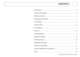
d. Use Figure 1 to identify and
remove wire "C" from the
"Common" terminal of the
existing remote switch.
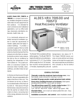
e. Use Figure 2 to remove and
reconnect wires "B" and "C" to
the "Common" terminal of the
remote switch. Use the supplied
piece of jumper wire if needed.
the wall to the BLUE wire on
the timer.
NOTE: The RED wire is not used
in a single-switch installation.
Cap with a twist connector.
c. Connect the GREEN wire on the
timer to the grounding screw in
the box.
d. Ensure all twist connectors are
tight.
3WAY SWITCH SETUP
NOTE:
The distance between the timer and
the remote switch must not exceed 100 feet.
a. Locate the COMMON wire that
was connected to the old switch
and connect it to the BLACK
7- Day Programmable Timer
2
American ALDES Ventilation Corporation • 4521 19th Street Court East, Suite 104 • Bradenton, FL 34203 – USA
941.351.3441 • 800.255.7749 • 941.351.3442 (fax) • [email protected] • www.aldes.us
© 2016 American ALDES Ventilation Corporation. Reproduction or distribution, in whole or in part, of this document, in any form or by any means, without the express written consent of
American ALDES Ventilation Corporation, is strictly prohibited. The information contained within this document is subject to change without prior written notice.
7-day programmable timer_iom_1016
FIGURE 1
f. Follow Figure 3 if a new single-
pole remote switch is being
used.
g. Place the wires into the timer
wall box.
h. Mount the back plate securely
to a wall box with the screws
provided in the parts package.
NOTE: Make sure the back plate
is at without any undue stress.
i. Re-install the front cover and
secure with the cover screw
supplied in the parts pack.
j. Follow steps h and i for the
remote 3-way switch.
OPERATION
Ensure that the installed timer displays
"MAN" mode on its display screen. Test
the connections by pressing the ON/
OFF button several times on the switch
timer. Each time this is done the timer
should "click" and the the controlled
device should turn on or o. To set or
rest the timer:
1. Hold down the ON/OFF button and
use a paperclip to press and release
the RESET button.
2. Continue to hold down the ON/
OFF button until INIT appears on
the screen.
3. Release ON/OFF.
The CR2 Lithium battery provides the
timer with two or more years of keeping
time without AC power. All personal
settings are saved in the timer once
installed, therefore, no resetting is
needed.
WARRANTY
1-year limited.
FIGURE 2
FIGURE 3
/